

Page 1
FAD ER CLEA N I N G
The RM THREE faders may need lubrication from time to time. This will extend
the fader life and eliminate any potential damage due to extended heavy usage.
Cleaning Instructions
1. Remove the fader to be cleaned by unscrewing the outer screws (removing
the 2 inner screws will detach the fader from the fader plate) and disconnecting
the cable coming from the mixer.
2. Spray a small amount of cleaner or lubricant into both ends of the fader and
slide the fader back and forth a few times to spread the fluid evenly throughout
the fader.
3. Shake and wipe off excess fluid before re-assembling the fader.
FAD ER RE PL AC E M E N T
To replace the cross or channel faders, follow step 1 of the cleaning instructions.
Replacement parts are available from Stanton or your local Stanton dealer.
LF-RM3 Channel input fader
CF-RM3 Crossfader
PS-18US US Power Supply (110v)
PS-18EU European Power Supply (220v)
PS-18UK UK only Power Supply (240v)
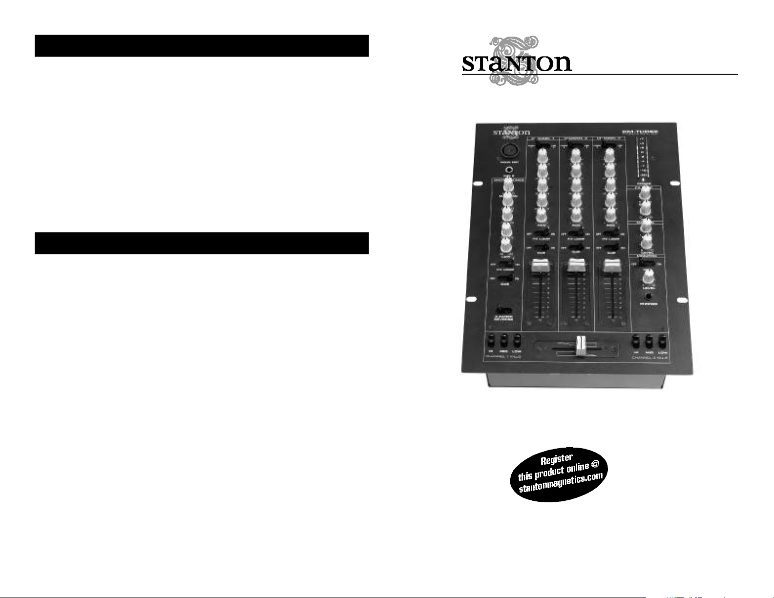
RM THREE
Professional performance mixer
© 1999, Stanton Magnetics, LLC
OWNER’S M A N U A L
Page 2

T RO U B LE S H O O TI N G
Thank you for making Stanton your first choice in professional DJ mixers.
This new, innovative family of mixers has been developed with input from the professional DJ community, bringing to the marketplace a previously unavailable, affordable combination of user-friendly, functional design, rugged construction, and professional quality features.
Stanton and your authorized Stanton dealer are dedicated to your complete satisfaction by offering benchmark service and support throughout the long life of your
Stanton product.
Again, we appreciate your patronage, and look forward to many years of making
music together.
PLEASE READ CAREFULLY BEFORE USE OF THIS PRODUCT
FA I LU R E TO FO LLOW T H E I NST RU C TI O N S P R I N TE D B E LOW M AY VO I D WA R R A N TY
• Follow all security advice printed on your mixer
• When removing the unit's AC plug from the power source, grasp and pull the
plug, NEVER the cord itself!
• Avoid placing your mixer near heat sources, such as power amplifiers.
• When in use, place your mixer on a stable surface, away from vibration. Always
use care when carrying your mixer. Impact, or heavy vibration may compromise
the unit's mechanical integrity. The manufacturer is not responsible for damage
resulting from an impact, or misuse.
• When in use, place your mixer away from sources of hum or noise, such as
transformers, or electric motors.
• To prevent overheating, always provide your mixer with adequate ventilation
air space.
• Avoid stepping on your mixer's AC cord. Repeated compression of the cord
may lead to electrical shorting.
• To avoid damage due to AC voltage peaks, always disconnect your mixer from
the power source during electrical storms.
• Your mixer contains no user-serviceable parts. The manufacturer is not
responsible for any damage or personal injury resulting from unauthorized
user-servicing or modifications. In addition, the warranty will be void if any
unauthorized service by the user is detected. Always return you mixer to an
authorized Stanton dealer for servicing.
Problem
Excessive hum when using
phono source.
Low frequency hum while
operating source unit.
Pro g ram volume can’t be
adjusted with master vo l u m e
c o n t ro l .
No powe r.
The amplifier is turned up,
but there is no signal.
No signal in headphones.
Cause
Poor ground connection.
Loose cartridge/headshell
connection.
Poor AC source ground.
Loose input/output connection. Shorted cable.
Amplifier or outboard gear
connected to the re c o r d output.
I m p roperly connected AC cord
or power line source not on.
B l own fuse.
Faulty output connections
Improper level adjustment.
Improper connection.
Improper level or cue mix
settings.
Solution
Properly connect turntable
ground wire to mixer ground
terminal.
Check cartridge connection
to headshell. Check headshell connection to tonearm.
Properly ground the AC
source. Check all input and
output connections for
s e c u re fit. Isolate and re p l a c e
the damaged cable.
Connect amplifier or outboard
gear to master output.
Properly connect AC cord to
AC power source. Turn powe r
o n .
Re m ove the fuse cover with a
flat-bladed scre wd r i ve r.
Replace fuse with a new
500mA fuse.
Properly connect amplifier, or
outboard gear to mixer.
Properly set crossfader,
channel faders, gain controls, and input selector toggles.
Check headphone connection to mixer. Tighten if necessary.
Adjust headphone level and
cue mix to the proper level
and channel settings.
Page 3

D E S C R I P T IO N O F FU N C TI O N S
1. Main microphone input: XLR connector
2. Microphone 2 input: 1/4” connector
3. Mic level controls: Controls the overall microphones output level
4. Mic EQ: Controls for low frequency, midrange, and high frequency
equalization of both microphones with (+/-12 dB) Note: Any changes made to
EQ settings will change the overall microphone output level
5. Effect ON/OFF switches: Turns effect send signal ON or OFF for each channel
6. Cue ON/OFF switches: Turns Cue signal ON or OFF for each channel
7. Input selector switches: Selects the audio signal source for each channel
8. Gain control: Controls the input sensitivity of each channel
9. EQ: Individual controls for low frequency, midrange, and high frequency
equalization with (+9/-26 dB) Note: Any changes made to EQ settings will
change the overall output level
10. Pan control: Controls left/right output balance of each channel
11. Channel faders: Controls the output level of each channel
12. Crossfader Reverse: Reverses the direction of the crossfader
13. Frequency Kill switches: Individual kill controls for low frequency, midrange,
and high frequency of channels 1 and 3
14. Crossfader: Fades the master output between channels 1 and 3.
15. Headphone output: Connection for 1/4 inch headphone. It is recommended
headphones with an impedance rating of 200 ohms or less be used for
maximum volume
16. Headphone level control: Controls the overall headphone output level. It is
recommended headphones with an impedance rating of 200 ohms or less be
used for maximum volume
17. Master Cue ON/OFF: Turns headphone output ON or OFF
18. Master level control: Controls the overall signal output level.
19. Master balance control: Controls left/right output balance of the
overall signal
20. Send level: Controls the level of the signal traveling to the external effects
unit used in the effects loop
21. Return level: Controls the overall level of the the external effects used in the
effects loop
22. Power indicator: Blue LED indicates whether mixer is ON or OFF
23. Level meter: Displays the level of the overall output stereo signal
24. Power switch: Turns the mixer "ON" or "OFF"
Page 4

25. Channel Inputs: 2 line and 1 phono inputs are provided for each channel.
Line inputs are used to connect to line level sources such as CD players,
MDs, DATs, samplers, etc. Phono inputs are used to connect to turntables.
26. Ground connector: Connects to the turntable ground connector to eliminate
electrical hum. Ground connectors are usually supplied with turntables
27. Master output: Connects to an amplifier, EQ, crossover, or other outboard
signal processing.
28. Send output: Connects to the input of an outboard signal processor (such as
the NEXT! DJS-24 digital sampler)
29. Return input: Connects to the output of the outboard signal processor to
create an effect loop
30. Power supply connector: Input connection for the accompanying power
supply.
TE C H N I CA L S P E C I FI C ATI O N S
Line inputs: 6 (RCA), 150 mV / 27K ohm
Phono inputs: 3 (RCA), 3 mV / 47K ohm
DJ mic input: 2 (XLR, 1/4“), 2.45 mV / 3K ohm
Effect Send: 1 (1/4”), 775mv
Effect Return: 1 (1/4”), 245mv
Master output: 1 (RCA), 775 mV / 1K ohm
Record output: 1 (RCA), 245 mV / 10K ohm
Headphone output: 1 (1/4”), 32 - 200 ohms recommended
Frequency Response: 20 Hz - 20 kHz, +/- 2 dB
Tone Control : + 9/-26 dB (Hi, Mid, Low)
Mic Tone: Hi/Mid/Lo +/-12 dB
Gain Control: 0-20dB
S/N Ratio: Less than 70dB
T.H.D: less than 0.2%
Dimension(LxWxD): 14” x 10
Weight: 8 lbs (3.6 Kg)
1/4
” x 4” (356 x 260 x 102 mm)
WA R R A N T Y
This unit has been designed and manufactured using quality
components. Therefore, it is warranted to be free from defects in materials (limited as specified below), and workmanship for a period of twelve
(12) months from the original purchase date. During this period, all
service and parts necessary to repair a defect will be free of charge. This
limited warranty applies to mechanical parts which are subject to wear
and tear as specified:
• Faders, specified durability: 15,000 cycles
• Rotary potentiometers, specified durability: 10,000 cycles
• Switches, specified durability: 10,000 cycles
Consequently, the parts listed above are warranted to be free from
defects in materials and workmanship for a period of thirty days (30)
days from the original purchase date.
FOR THE WA R R A N TY TO BE VA LID, PLEASE CO M PLE TE THE
O N LINE WA R R A N TY REGIST R ATION FORM FOUND AT
W W W. STA N TO N M AG N E TI CS . CO M
 Loading...