

Page 1
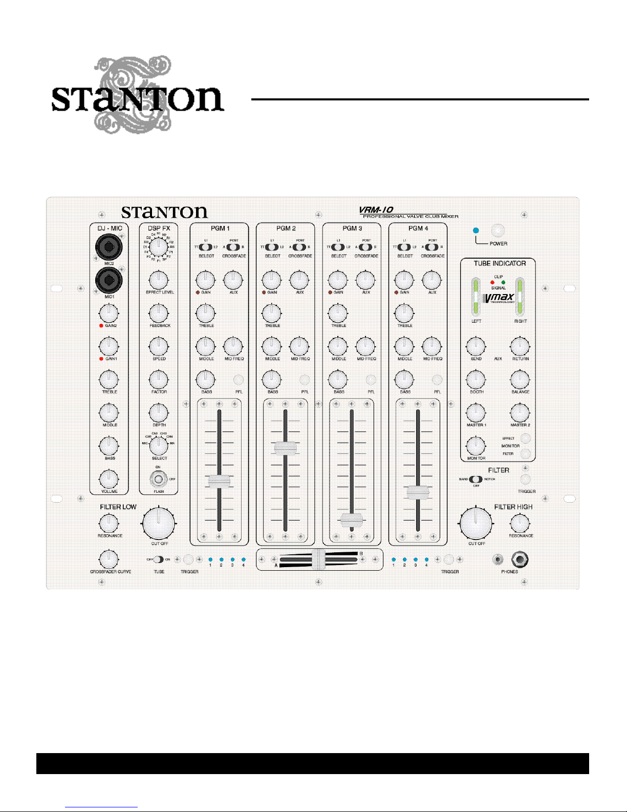
VRM-10
Professional Valve DJ mixer
OWNER’S M A N U A L
Page 2
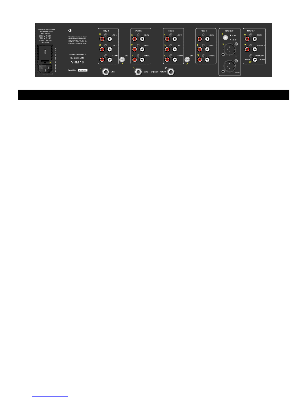
INPUTS AND OUTPUTS (Rear)
Aside from the headphone output and microphone jacks,
all connections are on the rear of the VRM10.
A Mains plug with fuse and voltage selector.
Changing the fuse: The lid for the housing of both fuses can
easily be opened by pressing both sides of the lid simultaneously. After changing the fuses, please make sure the lid
is closed securely. To switch the voltage selector it is also
necessary to open the fuse housing. You must now twist
the plug to the desired voltage setting. The selected voltage can be seen from outside. Make sure to replace the
fuses with the necessary value, as indicated on the back of
the mixer.
**MAINS PLUG MUST BE UNPLUGGED TO SELECT THE VOLTAGE**
B LINE INPUT for channel 4
C LINE INPUT for channel 4
D LINE INPUT for channel 3
E LINE INPUT for channel 3
F LINE INPUT for channel 2
G LINE INPUT for channel 2
H LINE INPUT for channel 1
I LINE INPUT for channel 1
LINE inputs 1 and 2 are for connecting devices with an output of up to +20dBu (i.e. CD, MD, DAT, etc...)
J PHONO INPUT for channel 4
K PHONO INPUT for channel 3
L PHONO INPUT for channel 2
M PHONO INPUT for channel 1
The PHONO inputs are for use with turntables with magnetic systems. They can perform best with levels form up to
-20dBu. There is an integrated RIAA-filter for each phono
input
N AUX
The auxiliary channel can be used for various applications
such as:
- Recording of individual or selection of various channels
- Monitoring of an individual or various channels
- Additional effect send for one or more channels (when
using an “empty” channel)
The volume can be set to 0dBu maximum and is controlled
in each channel individually with the AUX (25) control knob.
The signal for the auxiliary send is taken after the GAIN signal path, but before the EQ section (please also see the
block diagram).
O EFFECT SEND
P EFFECT RETURN
When using an external effects processor (such as the
Stanton DJF1 professional DJ filter) you must connect the
EFFECT SEND to the input of your processor and the
EFFECT RETURN to the output of your effects unit. The
input and output volumes can be at a maximum of 0dBu.
The volume can be set and controlled via the settings of
AUX SEND (47) and RETURN (48). The effect patch goes
through the MASTER-channel; the DJ-MIC signal will not
be affected (please also see the block diagram).
The 1/4” Jacks for EFFECT SEND, EFFECT RETURN and
AUX are set as follows:
TIP: LEFT
RING: RIGHT
SHAFT: GROUND
Q GROUND connection for turntable
If the connected turntable has a separate GROUND cable,
it must be connected with the screw Q to prevent ground
humming.
R Output attenuation selector for MASTER 1
S MASTER 1 LEFT
T MASTER 2 RIGHT
The main output MASTER 1 is equipped with balanced
(symmetrical) XLR jacks. The value of this output can be
selected either at +6 or 0dBu with the switch R. The value
of the output signal can also be individually set with the
MASTER (51) control.
The XLR’s are set as follows:
1: GND
2: +SIGNAL
3: -SIGNAL
1
Page 3
U BOOTH
The output value of the BOOTH is set at 0dBu. It can be
adjusted via the control knob BOOTH (49)
NOTE : BOOTH output is not affected by any balance/pan
setting (50).
NOTE: To achieve the optimum sound performance and
lowest signal-to-noise ratio it is essential in the digital output section to set the output impedance of the mixer to the
highest possible level (control 52) and if necessary to lower
the volume of the digital equipment connected to the
VRM10 receiving signal.
V MASTER 2
The output MASTER 2 is identical to MASTER 1. It has an
output impedance of +6dBu, which can be adjusted by the
MASTER 2 control.
W DIGITAL OUTPUT
The digital output of the VRM10 is equipped in the S/P DIF
standard. The signal path is switched parallel with MASTER
2 and can be controlled via the MASTER 2 (52) knob.
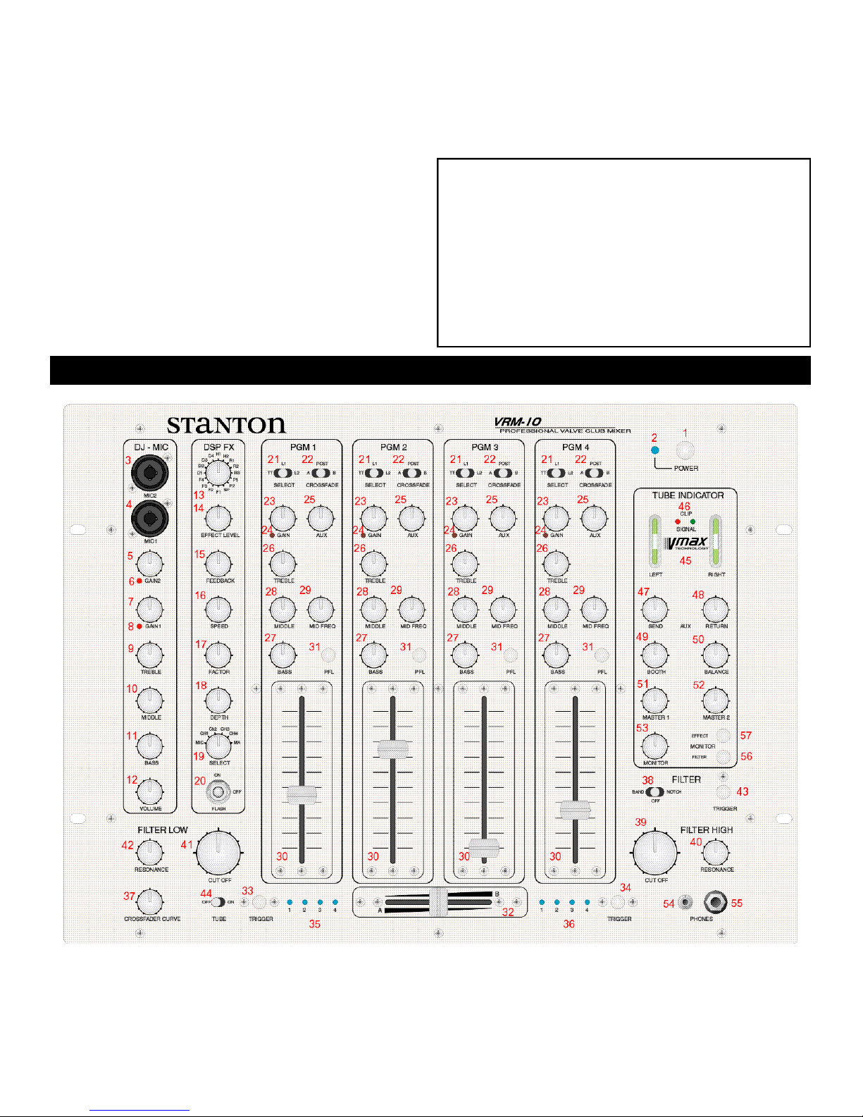
CONTROL INTERFACE (Front Panel)
The main outputs of the VRM10 (MASTER 1+ 2 and
BOOTH) are equipped with a special patented circuitry
to prevent crackling noise in the signal while switching
the unit on or/and off. In any case you should make sure,
that the mixer is switched on before the rest of your
equipment, i.e. especially amplification e.g. This will prevent possible damage to you speakers and PA system.
When turning off your equipment, you should proceed
the opposite way; this means: first turn off the amplification, then the VRM10 mixer.
1 Power On/Off
2 LED Power
After pressing the VRM10’s power switch, the blue power
LED will light up right away. The valves in the signal path of
the VRM10 will light up fully after a warm up period of 1-2
minutes.
2
Page 4

MICROPHONE CHANNEL
the level for the preamplification of the microphones.
3 DJ MIC 2
4 DJ MIC 1
Both mic inputs can be used as symmetrical or non- symmetrical (balanced or non-balanced) channels with either
XLR or 1/4” jacks, with the provided combo connectors
THE XLR jack are set as follows:
1 GND
2 +SIGNAL
3 -SIGNAL
THE 1/4” Jacks are set as follows:
TIP +SIGNAL
RING -SIGNAL
SHAFT GND
5 GAIN 2
6 CLIP LED for MIC 2
7 GAIN 1
8 CLIP LED for MIC 1
With the GAIN controls for both MIC channels you can set
INTERNAL DSP EFFECTS
9 TREBLE
10 MIDDLE
11 BASS
The 3 band EQ adjusts the equalization level for both
microphone inputs.
12 VOLUME
The volume control adjusts the equalization level for both
microphone inputs.
The Microphone channel is routed directly to the MASTER
section in the output (please also see block diagram).
This means:
- The microphone channel will not be influenced by the
external effect send
- The microphone channel can not be heard through
headphones
- The microphone channel will not be shown through the
indicator tubes in the master section
NOTE : The signal and clip led’s will be affected by the
microphone channel.
13 EFFECT SELECT
With this control you can select one of the 16 selectable effect presets:
POSITION TYPE CHARACTER TIME
H1 Hall Reverb Concert 2,4 sec
H2 Hall Reverb Arena 3,6 sec
R1 Room Club 1,8 sec
R2 Room Chamber 1,0 sec
R3 Room Garage 0,8 sec
P1 Plate Plate 2,0 sec
P2 Plate Vocal 1,5 sec
SP Spring 3,4 sec
F1 Chorus/ Flange 7m sec
F2 Chorus/ Flange 12m sec
F3 Chorus/ Flange 25m sec
F4 Chorus/ Flange 35m sec
D1 Stereo Delay 200m sec
D2 Stereo Delay 300m sec
D3 Stereo Delay 400m sec
D4 Stereo Delay 500m sec
14 EFFECT LEVEL
This controls the volume of the effect signal
15 FEEDBACK
With this control you can set the feedback of your selected
e ffect. This function only works with the CHORUS/
FLANGE and STEREO DELAY effects.
16 SPEED
With this control you can adjust the frequency of the LFO
(0.1-20 Hz). The LFO will affect all effects, depending on the
setting of the DEPTH control.
17 FACTOR
With this control you can adjust the Time factor of each
3
Page 5

effect individually. The middle position of this control will
have the value of the individual selected effect preset indicated in the diagram above.
18 DEPTH
With this control you can adjust the intensity of the LFO
19 SELECT
With this switch you can choose the channel on which the
effect should work. The following 6 positions are available:
27 BASS
28 MIDDLE
29 MID FREQ
With the EQ you can set the level of each frequency.
Furthermore the EQ can be used to isolate certain frequencies. This is very easy and effective with the high quality
and very strong filter-type parametric EQ on your VRM10.
NOTE : As the VRM-10’s EQ is so powerful, you may have
to carefully adjust the GAIN (23) while using the EQ (26-29)
MIC Microphone channel
CH1 PGM1
CH2 PGM2
CH3 PGM3
CH4 PGM4
MA Master section
20 ON / OFF / FLASH
With this switch you can turn the effect on or off. In the
FLASH position you can temporarily trigger the effect.
INPUT CHANNELS 1-4
Input channels 1-4 are identical. Therefore we will only
describe PGM1:
21 SELECT
With this switch you can select one of the three inputs:
TT PHONO (M)
L1 LINE 1 (I)
L2 LINE 2 (H)
22 CROSSFADER
This switch will select to which side of the crossfader the
the signal of the selected channel should be routed. The
blue LED’s to the left and right of the crossfader will indicate the chosen selection:
A The signal comes through the left side of the cross
fader
POST The signal bypasses the crossfader
B The signal comes through the right side of the
crossfader
23 GAIN
24 LED Clip
With this control you can set the volume of the incoming
signal of your selected input (SELECT 21). When setting
this control in the right position, the CLIP-LED will only light
up occasionally during really loud peaks of audio signals.
25 AUX
With this control you can set the volume and intensity of the
auxiliary output.
26 TREBLE
30 CHANNEL FADER
With the fader you can set the volume of the input channel
The VRM10 is equipped with high quality faders.
Nevertheless a fader has no life-time warranty (see warranty section) as it is used in a heavy duty way. If the
fader ever needs replaced, we have made it easy to be
replaced:Just loosen the 4 screws around the fader;
then disconnect the fader and replace with the new part.
Connect the fader back into the socket and screw the 4
screws back into their holes.
31 PFL
In the headphones you will hear the signal of the master
output if none of these buttons are activated: PFL (31),
EFFECT (57) and FILTER (56). If you press any PFL switch
you will here the selected audio signal before the master
output signal.
NOTE : It is possible to select more than one channel with
the PFL option.
CROSSFADER
32 Crossfader
With the crossfader you can control and mix the various
audio channels. You must have selected which channel
runs through the crossfader, though. This selection can be
made with the CROSSFADE switch (22).
Using modern VCA-technology in the VRM10 prevents
early damage of the crossfader. Nevertheless, once in a
while every fader gets worn out and needs to be
replaced. To change the crossfader easily you only need
to unscrew the two screws on the fader and disconnect
the socket. Then you need to connect the new fader and
put the screws back into their place.
33/34 TRIGGER
With both these buttons you can punch-in the audio signal
on whichever side of the crossfader you would like to hear
it, no matter in which position the crossfader is. By pressing both buttons you will hear both audio signals on either
side of the crossfader.
4
Page 6

35/36 CROSSFADE LED’s
The LED’s located left and right of the crossfader indicate,
which input channel lies on which side of the crossfader
according to the crossfader assign switch (22).
37 CROSSFADE CURVE
With this control you adjust the crossfade curve. When the
knob is set completely to the left, the crossfader curve is
set to a sharp on/off cut on both sides. If the knob is set
completely to the right, the crossfader will fade smoothly
from side to side.
DJ FILTER
The DJ Filter consists of two 24dB/Octave analog filters,
which can be combined by setting the FILTER SELECT
switch (38).
45 TUBE INDICATOR (MAGIC EYES)
Both indicator tubes for the left and the right channel will
indicate the output volume of the mixer, except the
MIC channels. When the tube lines meet in the middle you
have the ideal output peak. Additionally, the maximum peak
will be indicated by the master clip LED’s (46).
46 SIGNAL/ CLIP LED’s
The green LED’s will indicate a well balanced output signal.
To achieve the optimum peak level at maximum performance, the green LED’s should always light up, as soon as
any signal runs through your VRM10. The red LED’s will
indicate if the peak is too high. These red LED’s should only
peak occasionally within high volume passages from the
audio source fed through the mixer. If this is not possible
you may need to adjust the volume within the individual
channel faders.
38 FILTER SELECT
These positions are available:
BAND The filter works as bandpass
OFF The filter is switched off
NOTCH The filter works as a notch filter
39 CUT OFF HIGH
In the BAND position, this is used as a lowpass frequency
control. In the NOTCH position, it works as a highpass
frequency control.
40 RESONANCE HIGH
This creates a gradual increase of up to 6dB of resonance
of the CUTOFF frequency is as it turned to the right.
41 CUT OFF LOW
In the BAND position, this will act as highpass frequency
control. In the NOTCH position, it will act as lowpass
frequency control.
42 RESONANCE LOW
This creates a gradual increase of up to 6dB of resonance
of the CUTOFF frequency is as it turned to the right.
43 FLASH
The Flash function temporarily disables the filter while the
button is pressed.
NOTE : In BAND mode it may be possible to eliminate the
output signal totally if the controls are used heavily. The frequency controls (39 and 41) act as high torque kill switches.
47 SEND
With this you control the SEND volume of the external
effect path (max level is set at 0dBu).
48 RETURN
With this you control the volume of the external effect signal returned to the mixer.
NOTE : When the internal effect (19) is turned on and set to
MASTER (20), the external effect will be automatically
switched off.
49 BOOTH
With this you control the volume of the BOOTH output (max
level is set at 0dBu).
50 BALANCE
With this knob you can control the balance (pan) for the
MASTER outputs.
51 MASTER 1
With this knob you can control the MASTER 1 output volume [max level is set at 0dBu, or +6dBu according to the
attenuation switch located on the back panel (R)]
52 MASTER 2
With this knob you can control the MASTER 2 output volume (max level is set at +6dBu)
MONITOR
53 MONITOR
With this knob you can control the volume of the
headphones
MASTER SECTION
44 TUBE
This switch turns the tube-preamplifier on or off.
54 HEADPHONE JACK 3,5mm / 1/8”
55 HEADPHONE JACK 6,3mm / 1/4”
Both jacks are switched parallel. You can connect two pairs
of phones at the same time with an impedance of 30-400
5
Page 7

Ohm. You will hear the master signal in your headphones if
you haven’t selected any of these options: PFL (31),
EFFECT (57) and FILTER (56).
56 FILTER
When the FILTER switch (56) is selected, you will hear the
mixed master signal before the activated DJ filter or
master effect. When the FILTER switch is in its up position
TECHNICAL CHARACTERISTICS
(off), the master signal is set to post-filter.
57 EFFECT
By pressing the EFFECT switch you can pre-listen to the
internal effect signal.
NOTE : The PFL and EFFECT monitor switches must be off
monitor the filter from the headphone output.
Mic Inputs (Mic1 + Mic2)
Sensitivity -46dBu
Impedance 10kOhm
S/N Ratio >80dB
THD+Noise <0,1%
EQ High +/-15dB, 10kHz
EQ Mic +/-15dB, 1,1kHz
EQ Low +/-15dB, 50Hz
Input 1-4
Sensitivity -20dBu (Line1+2)
-60dBu (Phono/RIAA-Filter)
Impedance 100kOhm (Line1+2)
50kOhm (Phono)
S/N Ratio >85dB
THD+Noise <0,1%
EQ High +/-15dB
EQ Low +/-15dB
Parametric EQ +/-25dB (100Hz-10kHz)
AUX-Level 0dBu
Master
Effect-Loop 0dBu
Booth 0dBu
Master1 0/+6dBu switchable
Master2 +6dBu
Internal Effects
Frequency Range 20Hz-15kHz
THD+Noise 0,025%
S/N Ratio 86db
Effects 8 x Reverberation
4 x Delay
4 x Flanging
Filter
Mode Band/Notch
Frequency Range 50Hz-15kHz, 24dB/Octave
Resonance +6dB
Headphones
Impedance 30-200Ohms
Frequency Range 20Hz-20kHz
Mains
Power Consumption 50VA
Voltage Selector/Fuse 230V/500mA
115V/1A
100V/1A
Dimensions
Front 483mmx355mm (19"x8)
Chassis 436mmx352mmx100mm
Weight approximately 10kg
This unit has been designed and manufactured using quality components. Therefore, it is warranted to be free from
defects in materials (limited as specified below), and workmanship for a period of twelve (12) months from the original purchase date. During this period, all service and parts
necessary to repair a defect will be free of charge. This limited warranty applies to mechanical parts which are subject
to wear and tear as specified:
FOR THE WARRANTY TO BE VALID, PLEASE COMPLETE THE
ONLINE WARRANTY REGISTRATION FORM FOUND AT
Stanton Magnetics, LLC, 2821 Evans Street • Hollywood, FL 33020 (954) 929-8999 Fax: (954) 929-0333
WARRANTY
• Faders, specified durability: 15,000 cycles
• Rotary potentiometers, specified durability: 10,000 cycles
• Switches, specified durability: 10,000 cycles
Consequently, the parts listed above are warranted to be
free from defects in materials and workmanship for a period of thirty days (30) days from the original purchase date.
W W W. S TA N T O N M A G N E T I C S . C O M
© 2000, Stanton Magnetics, LLC
6
Page 8

BLOCK DIAGRAM
 Loading...