

Page 1
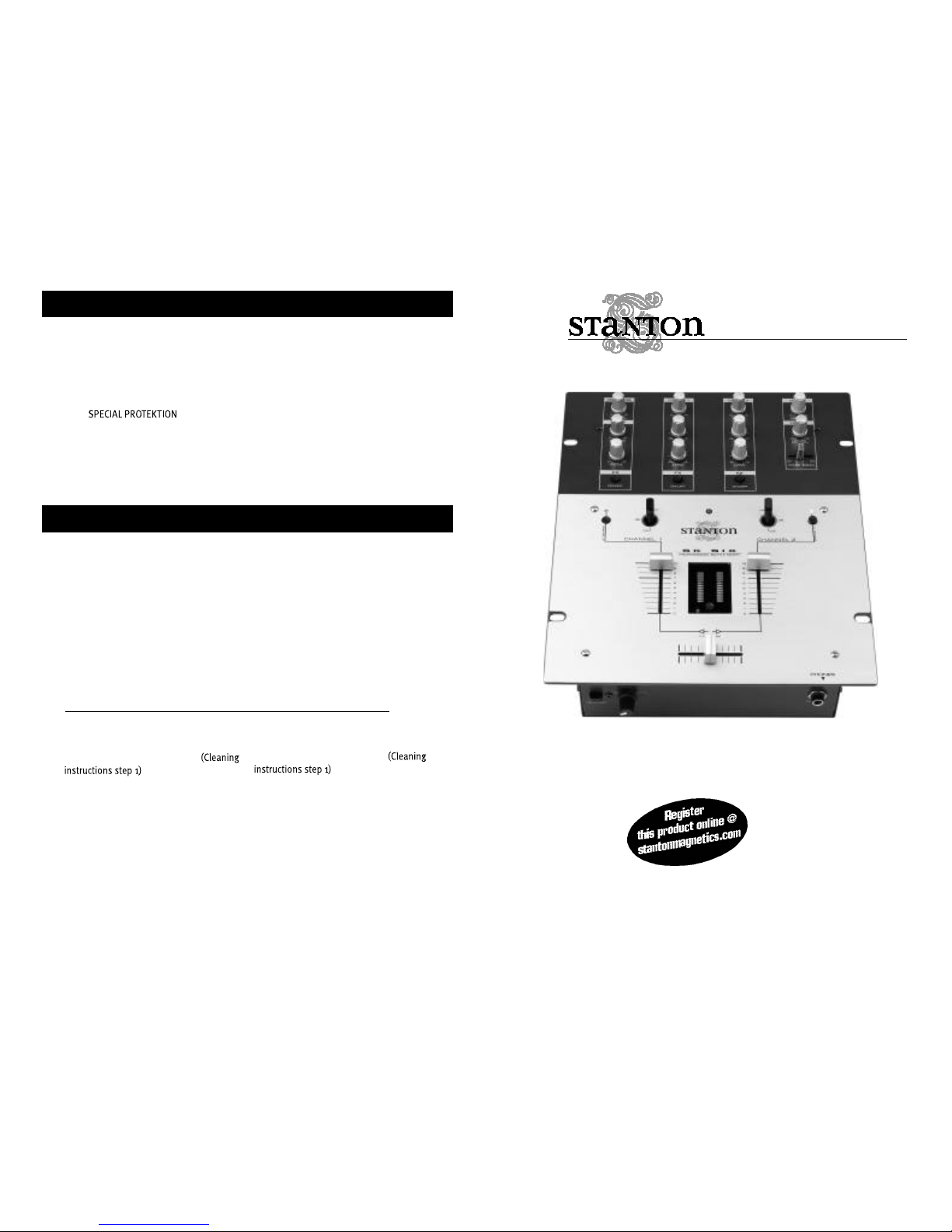
SK SIX
Professional performance mixer
STANTON MAGNETICS, LLC
2821 Evans St. Hollywood, FL 33020
(954) 929-8999 - Fax: (954) 929-0333
info@stantonmagnetics.com
OWNER’S M A N U A L
FA DER CLE A N I N G
The SK SIX faders may need lubrication from time to time. This will extend the
fader life and eliminate any potential damage due to extended heavy usage.
R E P L AC E M E N T PA R TS
To replace the cross or channel faders, follow steps 1 and 2 of the cleaning
instructions. The following replacement parts are available from Stanton or your
local Stanton dealer.
ROTATING AND REPLACING THE INPUT TOGGLE SWITCHES
Clea ning Instructions
1. Remove the 3 fader knobs and 4 screws
located in the corners of the PROTEKT™
(see “ ” inside) panel
and take the panel off the mixer.
2 . Remove the fader to be cleaned by
unscrewing the 2 outer screws (removing
the 2 inner screws will detach the fader
from the fader plate) and disconnect the
cable coming from the mixer.
3. Spray a small amount of cleaner or
lubricant into both ends of the fader and
slide the fader back and forth a few times
to spread the fluid evenly throughout the
fader.
4. Shake and wipe off excess fluid before
re-assembling the fader.
PL-SK6 Two way input toggle switch
3PL-SK6 Three way input toggle
switch with FLASH™
LF-SK6 Channel input fader
CF-SK6 Crossfader
PP-SK6 PROTEKT™ panel
PS-18US US Power Supply (110v)
PS-18EU European Power Supply (220v)
PS-18UK UK only Power Supply (240v)
ROTATING I NST RU C TI O N S
1 . Remove the PROTEKT™ panel
2. Remove the 2 outer screws from the
round plate (removing the 2 inner screws
will detach the switch from the plate)
3. Rotate the plate to the desired position
and tighten the screws back in the top and
bottom holes
R E PLAC I N G I NST RU C TI O NS
1. Remove the PROTEKT™ panel
2. Remove the 2 outer screws from the
round plate (removing the 2 inner screws
will detach the switch from the plate)
3. Remove the switch assembly and disconnect the cable coming from the mixer.
4. Set the replacement switch assembly in
the desired position and place the screws
back in the top and bottom holes.
© 1999, Stanton Magnetics, LLC
Page 2

PLEASE READ CAREFULLY BEFORE USE OF THIS PRODUCT
FA I LU R E TO FO LLOW T H E I NS T RU C TI O NS P R I N TE D B E LOW M AY VO I D WA R R A N TY
• Follow all security advice printed on your mixer
• When removing the unit's AC plug from the power source, grasp and pull the
plug, NEVER the cord itself!
• Avoid placing your mixer near heat sources, such as power amplifiers.
• When in use, place your mixer on a stable surface, away from vibration. Always
use care when carrying your mixer. Impact, or heavy vibration may compromise
the unit's mechanical integrity. The manufacturer is not responsible for damage
resulting from an impact, or misuse.
• When in use, place your mixer away from sources of hum or noise, such as
transformers, or electric motors.
• To prevent overheating, always provide your mixer with adequate ventilation
air space.
• Avoid stepping on your mixer's AC cord. Repeated compression of the cord
may lead to electrical shorting.
• To avoid damage due to AC voltage peaks, always disconnect your mixer from
the power source during electrical storms.
• Your mixer contains no user-serviceable parts. The manufacturer is not
responsible for any damage or personal injury resulting from unauthorized
user-servicing or modifications. In addition, the warranty will be void if any
unauthorized service by the user is detected. Always return you mixer to an
authorized Stanton dealer for servicing.
Thank you for making Stanton your first choice in professional DJ mixers.
This new, innovative family of mixers has been developed with input from the professional DJ community, bringing to the marketplace a previously unavailable, affordable combination of user-friendly, functional design, rugged construction, and professional quality features.
Stanton and your authorized Stanton dealer are dedicated to your complete satisfaction by offering benchmark service and support throughout the long life of your
Stanton product.
Again, we appreciate your patronage, and look forward to many years of making
music together.
Problem
Excessive hum when using
phono source.
Low frequency hum while
operating source unit.
Cause
Poor ground connection.
Loose cartridge/headshell
connection.
Poor AC source ground.
Loose input/output connection. Shorted cable.
Solution
Properly connect turntable
ground wire to mixer ground
terminal.
Check cartridge connection
to headshell. Check headshell connection to tonearm.
Properly ground the AC
source. Check all input and
output connections for
s e c u re fit. Isolate and re p l a c e
the damaged cable.
Pro g ram volume can’t be
adjusted with master vo l u m e
c o n t ro l .
No powe r.
Amplifier or outboard gear
connected to the re c o rd output.
I m p roperly connected AC cord
or power line source not on.
Connect amplifier or outboard
gear to master output.
Properly connect AC cord to
AC power source. Turn powe r
on.
The amplifier is turned up,
but there is no signal.
No signal in headphones.
Faulty output connections
Improper level adjustment.
Improper connection.
Improper level or cue mix
settings.
Properly connect amplifier, or
outboard gear to mixer.
Properly set crossfader,
channel faders, gain controls, and input selector toggles.
Check headphone connection to mixer. Tighten if necessary.
Adjust headphone level and
cue mix to the proper level
and channel settings.
T RO U B LE S H O O TI N G
Page 3

1. Mic level control: Controls the overall microphone output level.
2. Send: Controls the level of the effect send output. this is used to set the level of the
signal going to the outbpard effects processor or stomp box.
3. Return: Controls the level of the effect return input. This is used to control the level of
the processed signal going back into themixer
4. FX: Effect ON/OFF for each channel, MIC, and cue.
5. Gain: Controls the input level of each channel.
6. EQ: Individual controls for low and high frequency equalization with (+9/-26 dB)
Any changes made to EQ settings will change the overall output level.
7. Master level control: Controls the overall signal output level.
8. Headphone level control: Controls the overall headphone output level. It is recom-
mended headphones with an impedance rating of 200 ohms or less be used for maximum volume.
9. Cue pan: Fades the headphone output between channels 1 and 2, effectively allowing
the user to preview a mix.
10. Power indicator: Blue LED indicates whether mixer is ON or OFF.
11. Input selector switches: Selects phono or line inputs. FLASH™ position allows users
to quickly trigger the phono input.
12. Input Fader Reverse: Reverses the direction of each respective input channel fader.
Includes bi-color LED to indicate the status of the reverse function. When LED is
green, the fader is normal. When LED is red, the fader direction is reversed.
13. Channel fader: Controls the input channel level.
14. Headphone mute: Mutes the headphones without having to change its level.
15. Input Level Meter: Monitors each channel’s input level with peak hold function
16. Crossfader Reverse LED: Bi-color LED indicates the status of the crossfader reverse-
function. When LED is green, the crossfader is normal. When LED is red, the crossfader
direction is reversed.
17. Crossfader: Fades the master output between channels 1 and 2.
18. Headphone output: Connection for 1/4 inch headphone. Recommended headphone
impedance is 32-200 ohms for maximum volume.
19. Crossfader Reverse: Reverses the direction of the crossfader.
20. Crossfader Curve adjustment: Adjusts the shape of the crossfader curve from a quick
cut for scratching and cutting to a longer fade for mixing.
20. Send & return connections: The send output is used to connect the mixer to the line
input of your effects processor or sampler. The return input is used to feed the sgnal
D E S C R I P T IO N OF F U N C TI O N S
S P E C I A L P R OTE K TI O N
Your SK SIX comes with a special PROTEKT™ aluminum panel designed to
make the surface of the mixer is as smooth as possible while still enabling you
to field-replace key components. The PROTEKT™ panel covers all screws that
may get in the way of your performance. You can still easily remove the front
panel to replace any of the modular parts which are subject to wear and tear:
crossfader, input faders and input toggle switches.
The PROTEKT™ panel is also reversible. If you happen to scratch or blemish the
front side, just flip-it over since it is screened on both sides!
Page 4

back from the line output of the outboard unit. This creates the effects loop.
22. Power switch: Selects power "ON" or "OFF".
23. Power supply connector: Input connection for the accompanying power supply.
24. Master output: TRS balanced 1/4” master outputs.
25. Outputs: Record out and unbalanced master RCA.
26. Inputs: Line and phono signal inputs for channels 1 and 2. See note below.
27. Microphone input: 1/4” connector
28. Ground connectors: Connect to the turntables’ground connectors to eliminate electri-
cal hum. Ground connectors are usually supplied with turntables.
Note on audio signal inputs/outputs:
Line inputs are used to connect to line level
sources such as CD players, samplers, tape players, etc. Phono inputs are
used to connect to turntables. Master output connects to an amplifier, EQ,
crossover, or other outboard signal processing. Record out connects to tape
recorder, mini disk recorder, etc.
TE C H N I C A L S P E C I FI C AT I O N S
Line inputs: 2 (RCA), 150 mV / 27K ohm
Phono inputs: 2 (RCA), 3 mV / 47K ohm
Semd: 2 (1/4”), 150 mV / 27K ohm
Return: 2 (1/4”), 775 mV / 1K ohm
DJ mic input: 1 (1/4 inch), 1.5 mV / 3K ohm
Master output: 1 (1/4” TRS Balanced/RCA unbalanced),
1.2 V / 100 ohm
Record output: 1 (RCA), 245 mV / 100 ohm
Headphone output: 1 (1/4 inch), 32 - 200 ohms recommended
Crossfader type: VCA
Frequency Response: 20 Hz - 20 kHz, +/- 2 dB
Tone Control : + 9/-26 dB (Hi, Low)
Gain Control: 20dB / 1 Khz
S/N Ratio: Less than 70dB
T.H.D: less than 0.2%
Dimension(LxWxD): 12
3/8
” x 10
1/4
” x 4” ( 314 x 260 x 102 mm)
Weight: 7 lbs (3.2 Kg)
WA R R A N T Y
This unit has been designed and manufactured using quality
components. Therefore, it is warranted to be free from defects in materials (limited as specified below), and workmanship for a period of twelve
(12) months from the original purchase date. During this period, all
service and parts necessary to repair a defect will be free of charge. This
limited warranty applies to mechanical parts which are subject to wear
and tear as specified:
• Faders, specified durability: 15,000 cycles
• Rotary potentiometers, specified durability: 10,000 cycles
• Switches, specified durability: 10,000 cycles
Consequently, the parts listed above are warranted to be free from
defects in materials and workmanship for a period of thirty days (30)
days from the original purchase date.
FOR THE WA R R A N TY TO BE VA LID, PLEASE CO M P LE T E THE
O N LINE WA R R A N T Y REGIST R ATION FORM FOUND AT
W W W. STA N TO N M AG N E TI CS . CO M
2821 Evans Street • Hollywood, FL 33020
FU N C TI O N S ( c o n t ’d)
 Loading...