

Page 1
DJC.4
USER MANUAL
Page 2
IMPORTANT SAFETY INSTRUCTIONS
CAUTION: THE LIGHTNING FLASH WITH AN ARROWHEAD SYMBOL WITHIN AN EQUILATERAL
TRIANGLE IS INTENDED TO ALERT THE USER TO THE PRESENCE OF UN-INSULATED DANGEROUS
VOLTAGE WITHIN THE UNITS ENCLOSURE THAT MAY BE OF SUFFICIENT MAGNITUDE TO
CONSTITUTE A RISK OF ELECTRIC SHOCK TO PERSONS.
WARNING: THE EXCLAMATION POINT WITHIN AN EQUILATERAL TRIANGLE IS INTENDED
TO ALERT THE USER TO THE PRESENCE OF IMPORTANT OPERATING AND MAINTENANCE
(SERVICING) INSTRUCTIONS IN THE LITERATURE ACCOMPANYING THE PRODUCT.
NOTE: THE HAND WITHIN AN EQUILATERAL TRIANGLE IS INTENDED TO ALERT THE USER
TO SPECIFIC GUIDANCE AND INFORMATION REGARDING THE OPERATION OF THE UNIT, ND
SHOULD BE READ FULLY BEFORE USING THE UNIT FOR THE FIRST TIME.
CAUTION: TO REDUCE THE RISKS OF FIRE OR ELECTRIC SHOCK DO NOT REMOVE ANY COVERS,
OR OPEN THE UNIT. THERE ARE NO USER-SERVICABLE PARTS INSIDE. ALL SERVICING SHOULD
BE REFERRED TO QUALIFIED SERVICE ENGINEERS.
WARNING: READ AND FOLLOW ALL THE SAFETY AND OPERATING INSTRUCTIONS BEFORE
CONNECTING OR USING THIS UNIT. RETAIN THIS USER MANUAL FOR FUTURE REFERENCE. ALL
WARNINGS ON THE UNIT AND ITS PACKAGING SHOULD BE READ AND FOLLOWED.
WARNING: This product contains a chemical known to the State of California to cause cancer and birth
defects or other reproductive harm.
CAUTION: To reduce the risks of re or electric shock do not expose this product to rain or moisture. Do
not use this product near water; for example, near a bath tub, washbowl, kitchen sink, laundry tub, in a wet
basement or near a swimming pool. Unplug the unit from the wall outlet before cleaning. Never use thinner,
cleaning uids, solvents or chemically impregnated cloths. For cleaning always use a soft dry cloth. Unplug
this product during lightning storms or when unused for long periods of time.
CAUTION: The unit should be installed so that its location or position does not interfere with its proper
ventilation. For example, it should not be situated on a bed, sofa, rug or similar surface that may block the
ventilation openings; or placed in a built-in installation, such as a bookcase or cabinet, that may impede the
ow of air through its ventilation openings. The unit should be situated from heat sources such as radiators,
heat registers, stoves or other devices (including ampliers) that produce heat. No naked ame sources,
such as lighted candles, should be placed on, or near the unit.
WARNING: Do not place this unit on an unstable surface, cart, stand or tripod, bracket or table. The unit
may fall, causing serious injury to a child or adult and serious damage to the unit. Use only with a cart,
stand, tripod, bracket or table recommended by the manufacturer or sold with the unit. Any mounting of
the device on a wall or ceiling should follow the manufacturer’s instructions and should use a mounting
accessory recommended by the manufacturer. An appliance and cart combination should be moved with
care. Quick stops, excessive force and uneven surfaces may cause the appliance and cart combination
to overturn. Use only with the cart, stand, tripod, bracket, or table specied by the manufacturer, or sold
with the apparatus. When a cart is used, use caution when moving the cart/apparatus combination to avoid
injury from tip-over.
NOTE: Should the unit become damaged beyond repair, or reaches the end of its life, please consult the
regulations regarding disposal of electronic products in your region.
NOTE: S tanton Magnetics cannot be held responsible for damage, and, or including data loss caused by
improper use of the unit and or the applications provided for use with the unit.
Page 3
IMPORTANT SAFETY INSTRUCTIONS
CAUTION TO PREVENT ELECTRIC SHOCK, MATCH WIDE BLADE OF PLUG TO WIDE SLOT FULLY
INSERT.
ENGLISH: The apparatus shall be connected to a Mains socket outlet with a protective earthing connection.
GERMAN: Das Gerät ist eine Wandsteckdose mit einem Erdungsleiter angeschlossen werden.
FRENCH: L’appareil doit être connecté à une prise secteur avec connexion à la terre.
SPANISH: El aparato estará conectado a una toma de red eléctrica con una conexión a tierra.
ITALIAN: L’apparecchio deve essere collegato a una presa di rete con una connessione a terra protettiva.
1. The unit and power supply should only be connected to a power supply outlet only of the voltage and
frequency marked on its casing.
2. Protect the power cable from being walked on or pinched particularly at plugs, convenience receptacles,
and the point where they exit from the apparatus.
3. Do not defeat the safety purpose of the polarized or grounding-type plug. A polarized plug has two
blades with one wider than the other. A grounding type plug has two blades and a third grounding prong.
The wide blade or the third prong is provided for your safety. If the provided plug does not t into your
outlet, consult a qualied electrician for replacement of the obsolete outlet.
4. If the mains plug supplying this product incorporates a fuse then it should only be replaced with a fuse
of identical or lower rupture value.
5. Never use a damaged or frayed power cable; this can introduce serious risk of exposing lethal voltages.
6. The power supply cable of the unit should be unplugged from the wall outlet when it is to be unused for
a long period of time.
7. Only use attachments/accessories specied by the manufacturer.
DO NOT ATTEMPT SERVICING OF THIS UNIT YOURSELF. REFER SERVICING TO QUALIFIED
SERVICE PERSONNEL.
Upon completion of any servicing or repairs, request the assurance that only Factory Authorized
Replacement Parts with the same characteristics as the original parts have been used, and that the routine
safety checks have been performed to guarantee that the equipment is in safe operating condition.
REPLACEMENT WITH UNAUTHORIZED PARTS MAY RESULT IN FIRE, ELECTRIC SHOCK OR
OTHER HAZARDS.
ATTENTION POUR …VITER LES CHOC ELECTRIQUES, INTRODUIRE LA LAME LA PLUS LARGE DE
LA FICHE DANS LA BORNE
CORRESPONDANTE DE LA PRISE ET POUSSER JUSQUíAU FOND.
This unit should be serviced by qualied service personnel when:
The power cord or the plug has been damaged
Objects have fallen, or liquid has been spilled into the unit
The unit has been exposed to rain or liquids of any kind
The unit does not appear to operate normally or exhibits a marked change in performance
The device has been dropped or the enclosure damaged.
REGULATORY CERTIFICATION
Stanton Magnetics declare under our sole responsibility that this product, to which this declaration relates, is in
conformity with the following standards:
The Declarations of Conformity can be obtained from 382 Ave. de la Couronne, B-1050 Brussles
Authorized European representative: Phone: +3226450500 Fax: +326450505
Page 4

Features
Thank you for purchasing your new DJC.4 MIDI controller! The DJC.4 comes bundled with a four-deck version of Virtual DJ® LE,
which allows users to scratch and mix four decks of audio as well as control video. Its built-in audio interface allows users to
integrate turntables or CD decks into their performance. The control surface of the DJC.4 features large, touch-sensitive jog
wheels, offering users extremely tight scratch and pitch bend control.
Setup of the DJC.4 is easy. Users simply plug in the included USB cable, start up Virtual DJ LE and go. The one-to-one mapping
makes for a plug-in-and-play, out-of-the-box solution that eliminates all guesswork. The DJC.4 also includes shift functionality on
all buttons and encoders, ensuring future equipment and functionality can be added with ease.
Inputs: Line/Phone x 2 (RCA), MIC x 2, Aux x 1, USB type x 2
Out
puts: Master x 2, Headphone x 2
3
band EQ with Full output kill function for each channel
MP3
player/tablet friendly Aux input
MIC
input
Headphone with level control and cue mixing
Dual headphone jacks (1/4" and 3.5mm)
Dual 10 LED monitor display
DVS direct mode for timecode DJing software
Touch-sensitive jog wheels
Jog wheels sensor adjust knobs for each wheel
Installing ASIO Driver (Windows Only)
Before you can use your DJC.4 with a Windows PC, you need to install the ASIO driver. This can be found on the Stanton software
support CD. The ASIO lower latency to under 10 ms. You can configure the driver's settings using the Control Panel window.
PC SYSTEM REQUIREMENTS (Minimum system requirements):
- Intel Pentium II 450MHz CPU or comparable AMD CPU(recommend at least a
Pentium III CPU with 600M MHz) .
- Windows 98SE, ME, 2000, XP, Vista and Windows 7 operating system
- 1 available USB port
- At least 128MB RAM
- Software applications with ASIO support
Page 5

Specifications
1. GENERAL SECTION
POWER : DC6V, 2.0A
DIMENSION : 410 (W) X 297 (D) X 65 (H) mm
WEIGHT : 2.9 kg
2. INPUT/OUTPUT IMPEDANCE & SENSITIVITY: (MAXIMUM GAIN, load=100K)
INPUT IMPEDANCE AND REFERENCE INPUT LEVEL
LINE: 47K OHM /0dBV
PHONO: 47K OHM /-50dBV
MIC: 10K OHM /-54dBV
AUX: 47K OHM /0dBV
OUTPUT IMPEDANCE
MASTER: 300 OHM
BALANCED: 600 OHM
PHONES (load=32 ohm): 10 OHM
3. FREQUENCY RESPONSE: (MASTER GAIN MAX., MASTER OUT 0dB)
LINE: 20-20KHz +/-3dB
AUX: 20-20KHz +/-3dB
PHONO: 20-20KHz +1/-3dB (RIAA) (MASTER OUT -14dB)
MIC: 20-20KHz +2/-3dB
4. THD+N: (MASTER GAIN MAX., MASTER OUT 0dB, w/ 20kHz LPF, A-WEIGHTED)
LINE: LESS THAN 0.05% @ 1KHz
AUX: LESS THAN 0.05% @ 1KHz
PHONO: LESS THAN 0.15% @ 1KHz
MIC: LESS THAN 0.15% @ 1KHz
5. MAXIMUM INPUT: (MASTER GAIN MAX., 1KHz, THD=1%, w/20kHz LPF, A-WEIGHTED)
LINE: MORE THAN +6dBV
AUX: MORE THAN +6dBV
PHONO: MORE THAN -30dBV
MIC: MORE THAN -35dBV
6. MAXIMUM OUTPUT: (MASTER GAIN MAX., 1KHz, THD=1%, w/20kHz LPF, A-WEIGHTED)
MASTER: MORE THAN +6dBV (2V)
7. SIGNAL TO NOISE RATIO: (MASTER GAIN MAX., MASTER OUT 0dB, w/20KHz LPF, A-WEIGHTED)
LINE: MORE THAN 80dB
AUX: MORE THAN 80dB
PHONO: MORE THAN 80dB
MIC: MORE THAN 75dB
8. LR SEPARATION: (MASTER GAIN MAX., MASTER OUT 0dB, w/ 20kHz LPF, A-WEIGHTED)
LINE: MORE THAN 70dB
AUX: MORE THAN 70dB
PHONO: MORE THAN 70dB
9. CHANNEL BALANCE: WITHIN 2dB
Page 6

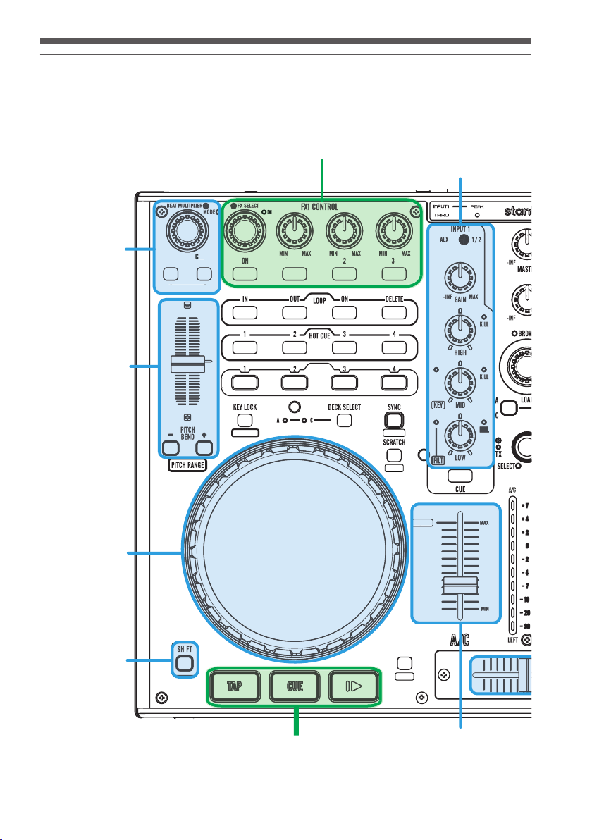
Controls and Functions
ADER FX
F
1. Input 1 LED
Indicates when INPUT 1 THRU is active.
When the INPUT 1 over 2V the PEAK LED will light.
2. Mic LED
Indicates the MIC is active.
3. Input 1 Source Switch
Switches between AUX or LINE/PHONO.
4. Input 2 Source Switch
Switches between MIC or LINE/PHONO2.
5. Master VoIume Control
This rotary knob is used to control the master output level
(volume). To avoid distorted output try to keep this knob as
low as possible.
DJC.4
1. Mic Input Jack
For plugging in a dynamic microphone.
2. Mic Level
Adjusts microphone volume input level.
3. Mic ON/OFF
Turns microphone ON/OFF.
4. Touch Sensor Level
Adjusts the static sensitivity of the platters on your DJC.4.
If you are having trouble with touch sensitivity, you can turn
these knobs up. If you are having troubles with the platters
detecting a touch without actually touching the platter, you
can turn this knob down. To disable touch sensivity entirely,
you can turn this knob all the way to the LEFT side.
5. X Fader Curve
Used to select the speed at which the volume raises/lowers
depending on crossfader position.
When the knob is set to
more gradual volume increase/decrease.
When the knob is set to the RIGHT, you will hear the other
the LEFT side
, you will have a
To avoid speaker damage that may be caused by excessive
volume, be sure to turn the Master Volume Control knob to
0 before turning on your DJC.4.
song come in very rapidly.
6. Mixing Mode Selector
This function allows you to monitor the CUE level as well as
the MASTER output in your headphones. In software that
provides a SPLIT CUE option, this provides a volume control
for the LEFT and RIGHT side of your headphones (CUE AND
MASTER).
7. Cue Level
This knob is used to adjust the headphone output level.
8. Headphone Jack
These jacks are used to connect your headphones to the
DJC.4, allowing you to monitor your mix. They can be used
simultaniously for lessons or tag-team DJing.
Always be sure the CUE LEVEL VOLUME is set to minimum
before you put your headphones on.
Page 7

Controls and Functions
1. Power Connector
A DC adaptor can be used when the USB port cannot provide
enough power to the unit. Please use only a 6V DC adaptor.
2. ON/OFF Switch
Turns the DJC.4 ON/OFF.
3. USB Port
Connects your DJC.4 to your computer for both audio and
power.
Note: maximum USB cable length is 3 meters.
4. Balanced TRS Master Output Jack
For connection to a professional amplifier or mixing console
with a balanced input.
5. Master Output (RCA) Jack
For connection to a consumer-level speaker system.
6. PH/LN Input Jack
These jacks are inputs for a phono (RIAA) stage for
magnetic (MM) cartridge or a line level device.
7. PH/LN Selector Switch
These switches are used to change the voltage line levels
of the respected PHONO/LINE RCA inputs jacks. When
connecting turntables with magnetic cartridges to these
jacks be sure the corresponding switch is in the "PHONO"
position, and when using line level input devices be sure the
switch is in the "LINE" position.
8. GND(Ground Terminal)
For turntable connection. Always use this connection when
using standard turntables with ground cable.
9. PH/THRU Switch
Send the AUX or LN/PH 1 signals directly to the master out
and disconnects the computer output.
Select the AUX or LN/PH1 from the Input 1
selection.
10. AUX IN
CD players, MP3 Player, Tablet Pad and other line level
instruments may only be connected to this jack. Input
volume will be controlled by the channel fader. The channel
SOURCE SELECTOR SWITCH must be in the "AUX".
11. Input Gain
These knobs are used to adjust the audio source signal input
gain for a channel. Never use the gain control to adjust a
channel output volume, as this can lead to distortion.
Page 8
Controls and Functions
SAMPLER VOLUME
FX CTRL 2
B/D
N
G
T
S
CROSSFADER
CHANNEL CUE CONTROL
FX C
0%
ON
CHANNEL FX CONTROL
(FADER FX Control Changes Line Faders to FX Controls)
CHANNEL EQ CONTROL
(Labeled Shift Function for Key/Filter)
QUICK LOOP
ACCESS
PITCH/TEMPO
JOG WHEEL
(PITCH/SCRATCH)
OOP LE
LOOP LENGTH
÷ x
÷ x
ON
H
0%
BEAT LOCK
FADER FX
SAMPLER
REVERSE
SMART
FX CTRL 1
TRL 1
A/C
SHIFT BUTTON
(Engages Secondary Labeled
Function On Many Controls )
DECK TRANSPORT CONTROL
SMART FADE
VIDEO
TRACK VOLUME
(FX Parameter When Fader FX Mode Is Engaged)
Page 9

Controls and Functions
S
CHANNEL CUE CONTROL
ON
ON
FADER FX
LOOP LENGTH
÷ x
LOOP CONTROL
HOT CUE CONTROL
SAMPLER
AMPLER
0%
SAMPLER PLAYBACK
DECK SELECT
REVERSE
SMART
B/D
FX CTRL 2
BEAT LOCK
CROSSFADER
Page 10

Connections
Microphone
MP3 Player
Main balanced power amplifier
Main unbalanced power amplifier
Computer
Turntable
CD/MP3 Player
Page 11

Setup
There are a number of default MIDI settings you can adjust directly from your hardware. You can set SHIFT button behavior, PUSHTO-KILL encoder behavior, and your MIDI channel. Your DJC.4 sends MIDI data over 4 channels at once, allowing a unique channel
message per deck.
CHANNEL
You can change channel by hold the LEFT DECK “DECK SWITCH” button for 3 seconds and press the Left Deck Hot Cue button 1 to 4.
Default channel is Channel 1~4
Hot Cue 1 for Channel 1~4
Hot Cue 2 for Channel 5~8
Hot Cue 3 for Channel 9~12
Hot Cue 4 for Channel 13~16
SETTING
You can, at any time, adjust the following settings. Make sure that you wish to change these settings though, as the default software
mappings that come with your DJC.4 are set from the factory.
•SHIFT button
You can change the SHIFT mode type from HOLD to TOGGLE by hold the left deck “DECK SWITCH” button for 3 seconds and press
the “Channel 1 Monitor Cue” button to switch the mode. Default setting is “HOLD” mode (SHIFT is only engaged when you press
and hold the button)
•Sampler
You can set your SAMPLER BUTTON(S) default from DECK to GLOBAL. The default (used by most DJ software) is DECK (sample
button note values are sent on a per-deck basis). You can change the Sampler setting by hold the left deck “DECK SWITCH”
button for 3 seconds and press the “Channel 2 monitor Cue” button to switch the mode.
.
•EQ KILL button
You can switch On/Off the EQ PUSH-TO-KILL function by holding the left deck “DECK SWITCH” button for 3 seconds, followed by
pressing the “Load B/D” button to switch the mode. The default setting enables EQ PUSH-TO-KILL.
Page 12

MIDI MAP
S
0
0
0
0
0
0
0
0
0
0
0
0
0
0
0
0
0
0
0
0
0
0
0
0
0
0
0
0
0
0
1
.K ey & Kn ob
Button MIDI Command MIDI Command
AUTO_LOOP 09,9n,01,7F 09,9n,01,00 0x33
AUTO_LOOP(knob) 0B,Bn,01,41(Increment) 0B,Bn,01,3F(Decrement) 0x1F
Loop - 09,9n,02,7F 09,9n,02,00
Loop X 09,9n,03,7F 09,9n,03,00
PITCH_FADER 0E,En,00,00 0E,En,7F,7F
IN 09,9n,04,7F 09,9n,04,00
OUT 09,9n,05,7F 09,9n,05,00
LOOP_ACTIVE 09,9n,06,7F 09,9n,06,00
DELETE 09,9n,07,7F 09,9n,07,00
HOT_CUE1 09,9n,08,7F 09,9n,08,00
HOT_CUE2 09,9n,09,7F 09,9n,09,00
HOT_CUE3 09,9n,0A,7F 09,9n,0A,00
HOT_CUE4 09,9n,0B,7F 09,9n,0B,00
SAMPLE1 09,9n,0C,7F 09,9n,0C,00 0x3E
SAMPLE2 09,9n,0D,7F 09,9n,0D,00
SAMPLE3 09,9n,0E,7F 09,9n,0E,00 0x40
SAMPLE4 09,9n,0F,7F 09,9n,0F,00 0x41
KEY_LOCK 09,9n,10,7F 09,9n,10,00
DECK 09,9n,11,7F 09,9n,11,00
SYNC 09,9n,12,7F 09,9n,12,00
PITCH_BEND- 09,9n,13,7F 09,9n,13,00 0x45
PITCH_BEND+ 09,9n,14,7F 09,9n,14,00 0x46
SCRATCH 09,9n,15,7F 09,9n,15,00 0x47
JOG_WHEEL_TOUCH 09,9n,26,7F 09,9n,26,00
JOG_WHEEL 0B,Bn,02,41++(Forward) 0B,Bn,02,3F--(Reverse)
CUE_PLAY 09,9n,16,7F 09,9n,16,00
CUE 09,9n,17,7F 09,9n,17,00 0x49
PLAY 09,9n,18,7F 09,9n,18,00
GAIN 0B,Bn,03,00(Minimum) 0B,Bn,03,7F(Maximum)
HIGH_KILL 09,9n,19,7F 09,9n,19,00
HIGH(knob) 0B,Bn,04,00(Minimum) 0B,Bn,04,7F(Maximum) 0x22
MID_KILL 09,9n,1A,7F 09,9n,1A,00
MID(knob) 0B,Bn,05,00(Minimum) 0B,Bn,05,7F(Maximum) 0x23
LOW_KILL 09,9n,1B,7F 09,9n,1B,00
LOW(knob) 0B,Bn,06,00(Minimum) 0B,Bn,06,7F(Maximum) 0x24
CH_CUE 09,9n,1C,7F 09,9n,1C,00 0x4E
CHANNEL_FADER 0B,Bn,07,00(Minimum) 0B,Bn,07,7F(Maximum) 0x25
LOAD_AC 09,9n,22,7F 09,9n,22,00 0x54
LOAD_BD 09,9n,23,7F 09,9n,23,00 0x55
FX(2)_SELECT 09,9n,1D,7F 09,9n,1D,00
FX(2)_SELECT(knob) 0B,Bn,08,41(Increment) 0B,Bn,08,3F(Decrement)
FX(2)_ON 09,9n,1E,7F 09,9n,1E,00 0x50
FX(2)_EFX1 09,9n,1F,7F 09,9n,1F,00
FX1(2)_EFX1(knob) 0B,Bn,09,00(Minimum) 0B,Bn,09,7F(Maximum)
FADER_FX(2)_EFX2 09,9n,20,7F 09,9n,20,00
FX1(2)_EFX2(knob) 0B,Bn,0A,00(Minimum) 0B,Bn,0A,7F(Maximum) 0x28
FX1(2)_EFX3 09,9n,21,7F 09,9n,21,00 0x53
FX1(2)_EFX3(knob) 0B,Bn,0B,00(Minimum) 0B,Bn,0B,7F(Maximum) 0x29
Button MIDI Command MIDI Command
SHIFT 09,9n,2D,7F 09,9n,2D,00
SAMPLE VOLUME 0B,Bn,0D,00(Minimum) 0B,Bn,0D,7F(Maximum)
BROWSER 09,9n,27,7F 09,9n,27,00
BROWSER(knob) 0B,Bn,0E,41(Increment) 0B,Bn,0E,3F(Decrement) 0x2C
VIDEO 09,9n,28,7F 09,9n,28,00
LEFT and RIGHT DECK
CENTER DECK
HIFT+
x34
x35
x36
x37
x38
x39
x3A
x3B
x3C
x3D
x3F
x42
x43
x44
x58
x20
x48
x4A
x21
x4B
x4C
x4D
x4F
x26
x51
x27
x52
x2B
x59
x5A
Page 13

MIDI MAP
VIDEO(knob) 0B,Bn,0F,41(Increment) 0B,Bn,0F,3F(Decrement) 0x2D
AUDIO_CROSS_FADER 0B,Bn,10,00(Minimum) 0B,Bn,10,7F(Maximum) 0x2E
VIDEO_CROSS_FADER 0B,Bn,11,00(Minimum) 0B,Bn,117F(Maximum) 0x2F
SMART_XF 09,9n,24,7F 09,9n,24,00 0x56
XF_LINK 09,9n,25,7F 09,9n,25,00 0x57
CF_CURVE 0B,Bn,12,00(Minimum) 0x30
CUE_MIXING 0B,Bn,13,00(Minimum) 0x31
CUE_LEVEL 0B,Bn,14,00(Minimum) 0B,Bn,14,7F(Maximum) 0x32
2. Le ds
LEFT and RIGHT DECK
LEDs LED ON LED OFF
Loop - 09,9n,02,7F 09,9n,02,00
Loop X 09,9n,03,7F 09,9n,03,00
IN 09,9n,04,7F 09,9n,04,00
OUT 09,9n,05,7F 09,9n,05,00
LOOP_ACTIVE 09,9n,06,7F 09,9n,06,00
DELETE 09,9n,07,7F 09,9n,07,00
HOT_CUE1 09,9n,08,7F 09,9n,08,00
HOT_CUE2 09,9n,09,7F 09,9n,09,00
HOT_CUE3 09,9n,0A,7F 09,9n,0A,00
HOT_CUE4 09,9n,0B,7F 09,9n,0B,00
SAMPLE1 09,9n,0C,7F 09,9n,0C,00
SAMPLE2 09,9n,0D,7F 09,9n,0D,00
SAMPLE3 09,9n,0E,7F 09,9n,0E,00
SAMPLE4 09,9n,0F,7F 09,9n,0F,00
KEY_LOCK 09,9n,10,7F 09,9n,10,00
SYNC 09,9n,12,7F 09,9n,12,00
PITCH_BEND- 09,9n,13,7F 09,9n,13,00
PITCH_BEND+ 09,9n,14,7F 09,9n,14,00
SCRATCH 09,9n,15,7F 09,9n,15,00
CUE_PLAY 09,9n,16,7F 09,9n,16,00
CUE 09,9n,17,7F 09,9n,17,00
PLAY 09,9n,18,7F 09,9n,18,00
HIGH_KILL 09,9n,19,7F 09,9n,19,00
MID_KILL 09,9n,1A,7F 09,9n,1A,00
KEY_ON 09,9n,26,7F 09,9n,26,00
LOW_KILL 09,9n,1B,7F 09,9n,1B,00
FILTER_ON 09,9n,27,7F 09,9n,27,00
CH_CUE 09,9n,1C,7F 09,9n,1C,00
CH_METER1 0B,Bn,02,0C 0B,Bn,02,00
CH_METER2 0B,Bn,02,18 0B,Bn,02,00
CH_METER3 0B,Bn,02,24 0B,Bn,02,00
CH_METER4 0B,Bn,02,30 0B,Bn,02,00
CH_METER5 0B,Bn,02,3C 0B,Bn,02,00
CH_METER6 0B,Bn,02,48 0B,Bn,02,00
CH_METER7 0B,Bn,02,54 0B,Bn,02,00
CH_METER8 0B,Bn,02,60 0B,Bn,02,00
CH_METER9 0B,Bn,02,6C 0B,Bn,02,00
CH_METERA 0B,Bn,02,78 0B,Bn,02,00
FX1(2)_ON 09,9n,1E,7F 09,9n,1E,00
FX1(2)_EFX1 09,9n,1F,7F 09,9n,1F,00
FX1(2)_EFX2 09,9n,20,7F 09,9n,20,00
FX1(2)_EFX3 09,9n,21,7F 09,9n,21,00
LOAD_AC 09,9n,22,7F 09,9n,22,00
LOAD_BD 09,9n,23,7F 09,9n,23,00
0B,Bn,12,7F(Maximum)
0B,Bn,13,7F(Maximum)
Page 14
MIDI MAP
0
0
0
0
0
0
0
4
8
LEDs LED ON LED OFF
TX 09,9n,2E,7F
FX 09,9n,2F,7F
VIDEO_XF 09,9n,24,7F
XF_LINK 09,9n,25,7F 09,9n,25,00
MASTER_METER_L1 0B,Bn,03,0C 0B,Bn,03,00
MASTER_METER_L3 0B,Bn,03,24
MASTER_METER_L2 0B,Bn,03,18 0B,Bn,03,00
MASTER_METER_L4 0B,Bn,03,30 0B,Bn,03,00
MASTER_METER_L5 0B,Bn,03,3C 0B,Bn,03,00
MASTER_METER_L6 0B,Bn,03,48
MASTER_METER_L7 0B,Bn,03,54 0B,Bn,03,00
MASTER_METER_L8 0B,Bn,03,60 0B,Bn,03,00
MASTER_METER_L9 0B,Bn,03,6C 0B,Bn,03,00
MASTER_METER_LA 0B,Bn,03,78 0B,Bn,03,00
MASTER_METER_R1 0B,Bn,04,0C 0B,Bn,04,00
MASTER_METER_R2 0B,Bn,04,18 0B,Bn,04,00
MASTER_METER_R3 0B,Bn,04,24 0B,Bn,04,00
MASTER_METER_R4 0B,Bn,04,30 0B,Bn,04,00
MASTER_METER_R5 0B,Bn,04,3C 0B,Bn,04,00
MASTER_METER_R6 0B,Bn,04,48
MASTER_METER_R7 0B,Bn,04,54 0B,Bn,04,00
MASTER_METER_R8 0B,Bn,04,60 0B,Bn,04,00
MASTER_METER_R9 0B,Bn,04,6C 0B,Bn,04,00
MASTER_METER_RA 0B,Bn,04,78 0B,Bn,04,00
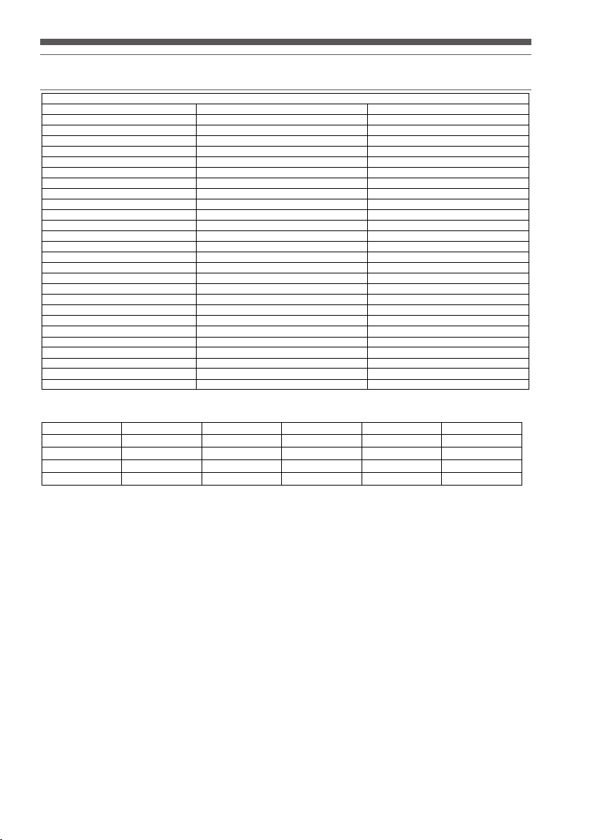
DECK A DECK B DECK C DECK D CENTER
Mode1(n) 0 1 2 3
Mode2(n) 4 5 6 7
Mode3(n) 8 9 10 11
Mode4(n) 12 13 14 15 12
CENTER DECK
9,9n,2E,00
9,9n,2F,00
9,9n,24,00
B,Bn,03,00
B,Bn,03,00
B,Bn,04,00
Page 15

FAQ/TROUBLESHOOTING
1. My EQ Kill knobs do not work.
-You can switch On/Off the EQ PUSH-TO-KILL function by holding the left deck “DECK SWITCH” button for
3 seconds, followed by pressing the “Load B/D” button to switch the mode. The default setting enables EQ
PUSH-TO-KILL.
2. I am getting an error message when I plug in my device that says "TBIA-The Data Is Invalid".
-This error is related to other audio devices you may have installed on your Windows PC and lower-quality ASIO
drivers. Please try uninstalling your device and reinstalling.
3. I have Virtual DJ Pro, and the controller isn't working/don't have the correct skin that comes with Virtual DJ
LE.
-You can download the latest skins and configuration files from www.virtualdj.com. This is available to all
registered customers of Virtual DJ Pro.
4. I am getting pops/cracks/digital artifacts in my audio.
-Please raise your latency settings in your software of choice. Often times, this is directly related to running
the application on very low latency settings on a lower-specification computer, and can be resolved by rasing
the latency just a bit.
5. I use software other than Virtual DJ.
-Please go to www.stantondj.com for updated preset/mapping files for other popular DJ software.
6. My wheels don't scratch/I can get them to stop the audio when I am not touching the platters.
-Please check the position of the "Wheel Sensitivity" knobs on the front of your DJC.4 These knobs, if turned
all the way to the left, can cause the platters to not respond to touch, and, if turned too far to the right, can
cause the platters to respond even if your hand is not resting on the platter.
7. I want to obtain a copy of Virtual DJ Pro. Is there a discount?
-Yes, please go to www.virtualdj.com and register your Virtual DJ LE serial number. There is a special discount
offer made to users to purchase Virtual DJ Pro at a reduced price.
Page 16

NOTES
Page 17

NOTES
Page 18

WARRANTY
Thank you for choosing one of Gibson Pro Audio’s brands (Stanton, KRK, or Cerwin Vega!).
Your satisfaction is extremely important to us. We proudly stand behind the quality of our work and appreciate that you put your trust in
us. Registering your merchandise will help us guarantee that you are kept up to date on our latest advances.
To Register Merchandise Purchased from an Authorized Gibson Pro Audio Dealer in the U.S.:
Please go to: http://www.gibson.com and register online.
Or you may send your warranty card to:
Gibson Customer Service
309 Plus Park Blvd.
Nashville, TN 37217
If you have any questions you may contact customer service at:
1-800-4GIBSON (1-800-444-2766)
e-mail: service@gibson.com
FOR MERCHANDISE PURCHASED FROM AN AUTHORIZED GIBSON PRO AUDIO DISTRIBUTOR OUTSIDE OF THE US, PLEASE CONTACT
THE DISTRIBUTOR FROM WHOM YOU PURCHASED YOUR MERCHANDISE FOR TO REGISTER YOUR WARRANTY AND FOR HANDLING AND
RESOLUTION OF ALL WARRANTY-RELATED ISSUES.
Gibson Pro Audio Warranty
If at any time your Gibson Pro Audio product (which includes Stanton, KRK, or Cerwin Vega! brands) malfunctions as a result of faulty
materials or workmanship, Gibson Pro Audio or one of Gibson Pro Audio’s Authorized Service Centers in the US will repair the defect(s) or
replace the merchandise, as it deems appropriate at its sole discretion.
Warranty Period (from date of Purchase as listed on the Bill of Sale):
Stanton
One (1) year for all Stanton products.
KRK
Three (3) years from all studio monitors.
One (1) year all headphones, computer audio devices, including room correction devices.
Cerwin Vega!
Five (5) years for all passive speaker systems.
Three (3) years for all active speaker systems.
One (1) year for mixers.
Page 19

Gibson will warrant all replacement parts and repairs for ninety (90) days from the date of original shipment.
In the unlikely event that your merchandise is destroyed, lost or damaged beyond repair while in the possession of Gibson or one of Gibson Pro
Audio’s Authorized Service Centers for repair, Gibson will replace that merchandise with one of the same or most similar style of a value not in
excess of the original purchase price of your merchandise. Any insurance covering the merchandise, including but not limited to collector's value
insurance, must be carried by owner at owner's expense.
For the fastest and safest merchandise return, please use the original shipping carton and packaging materials. Gibson cannot be responsible
for any damages incurred during the shipping process due to poor or inadequate packing.
THIS WARRANTY IS EXTENDED TO THE ORIGINAL RETAIL PURCHASER ONLY AND MAY NOT BE TRANSFERRED OR ASSIGNED TO SUBSEQUENT
OWNERS. IN ORDER TO VALIDATE YOUR WARRANTY, AND AS A CONDITION PRECEDENT TO WARRANTY COVERAGE HEREUNDER, YOU MUST REGISTER
YOUR WARRANTY WITHIN FIFTEEN (15) DAYS FOLLOWING THE ORIGINAL DATE OF PURCHASE.YOUR PROOF OF PURCHASE OR SALES RECEIPT MUST
ACCOMPANY ALL REQUESTS FOR WARRANTY COVERAGE.
This warranty is subject to the following limitations:
THIS WARRANTY DOES NOT COVER
1. Any merchandise that has been altered or modified in any way or upon which the serial number has been tampered with or altered.
2. Any merchandise whose warranty card has been altered or upon which false information has been given.
3. Any merchandise that has been damaged due to misuse, negligence, or improper operation.
4. Any merchandise that has been damaged by accident, flood, fire, lightening, or other acts of God.
5. Shipping damage of any kind.
6. Any merchandise that has been subjected to extremes of humidity or temperature.
7. Any merchandise that has been purchased from an unauthorized dealer, or upon which unauthorized repair or service has been performed.
GIBSON MAKES NO OTHER EXPRESS WARRANTY OF ANY KIND WHATSOEVER. ALL IMPLIED WARRANTIES, INCLUDING WARRANTIES OF
MERCHANTABILITY AND FITNESS FOR A PARTICULAR PURPOSE, EXCEEDING THE SPECIFIC PROVISIONS OF THIS WARRANTY ARE HEREBY
DISCLAIMED AND EXCLUDED FROM THIS WARRANTY. SOME STATES AND/OR COUNTRIES DO NOT ALLOW THE EXCLUSION OR LIMITATION OF
IMPLIED WARRANTIES SO THAT THE ABOVE MAY NOT APPLY TO YOU.
GIBSON SHALL NOT BE LIABLE FOR ANY SPECIAL, INDIRECT CONSEQUENTIAL, INCIDENTAL OR OTHER SIMILAR DAMAGES SUFFERED BY THE
PURCHASER OR ANY THIRD PARTY, INCLUDING WITHOUT LIMITATION, DAMAGES FOR LOSS OF PROFITS OR BUSINESS OR DAMAGES RESULTING
FROM USE OR PERFORMANCE OF THE MERCHANDISE, WHETHER IN CONTRACT OR IN TORT, EVEN IF GIBSON OR ITS AUTHORIZED REPRESENTATIVE
HAS BEEN ADVISED OF THE POSSIBILITY OF SUCH DAMAGES, AND GIBSON SHALL NOT BE LIABLE FOR ANY EXPENSES, CLAIMS, OR SUITS ARISING
OUT OF OR RELATING TO ANY OF THE FOREGOING.
FOR MERCHANDISE PURCHASED FROM AN AUTHORIZED GIBSON PRO AUDIO DISTRIBUTOR OUTSIDE OF THE US, PLEASE CONTACT THE DISTRIBUTOR
FROM WHOM YOU PURCHASED YOUR MERCHANDISE FOR THE HANDLING AND RESOLUTION OF ALL WARRANTY ISSUES. FOR THESE PURCHASES,
THE ABOVE-DESCRIBED WARRANTY IS NOT APPLICABLE.
How to Obtain Warranty Service
Warranty Service outside the United States:
To initiate a warranty repair, please contact the Authorized Gibson Pro Audio distributor from whom you purchased your merchandise, and follow
the distributor’s return/warranty policy.
Warranty Service for Merchandise Purchased from an Authorized Gibson Pro Audio Dealer in the U.S:
In the event of malfunction of your Gibson Pro Audio merchandise, the Dealer or Owner must call Customer Service @ 1-800-4GIBSON (1-800444-2766) and obtain a Return Authorization number from the customer service agent. No merchandise may be returned to Gibson without
such prior Return Authorization, and the Return Authorization number must be written on the outside of the shipping package. The Customer
Service agent will provide the address and additional shipping instructions. Owner must ship the merchandise, freight, and insurance pre-paid
to the address provided by the customer service representative. Only Authorized Gibson Pro Audio Service Centers may perform warranty service
and any service performed by unauthorized persons will void this warranty. Gibson disclaims liability for defects or damage caused by services
performed by unauthorized persons or non-warranty service not performed by Gibson or an Authorized Gibson Pro Audio Service Center.
Page 20

When contacting Gibson, you must include a complete written description of the malfunction of the merchandise. If non-warranty work
is required or recommended, a quotation will be issued and must be approved by you before any non-warranty work is commenced. You
should consider quotations obtained for non-warranty work immediately and advise the Authorized Gibson Pro Audio Service Center
or Gibson of your wishes. You are not required to purchase non-warranty work in order to obtain service on materials covered by this
warranty. Following its inspection of merchandise upon its arrival, Gibson or the Authorized Gibson Pro Audio Service Center will advise
you or your dealer of the approximate date of completion. The repaired merchandise or part will be returned to you or your dealer, freight
collect insured.
No representative or other person is authorized to assume for Gibson any liability except as stated in this warranty. This warranty gives
you specific rights which vary from state to state or from country to country.
For further information, write:
Customer Service Dept.,
Gibson Customer Service
309 Plus Park Blvd.
Nashville, TN 37217
Or call:
1-800-4GIBSON
Microsoft® Windows™ is a registered trademark of Microsoft® Corp. Apple® OSX™ is a registered trademark of
Apple® Corp.Virtual DJ™ is a registered trademark of Atomix™ Productions
Page 21

 Loading...