

Page 1

C.502
/ /
USER MANUAL
Page 2
IMPOR TA NT SAFETY P R EC AU TIONS
1. Read Instructions - All the safety and operating instructions should
be read before this product is operated.
2. Retain Instructions - The safety and operating instructions should be
retained for future reference.
3. Heed Warnings - All warnings on the appliance and in the operating
instructions should be adhered to.
4. Follow Instructions - All operating and use instructions should be
followed.
5. Water and Moisture - The appliance should not be used near water
- for example, near a bathtub, washbowl, kitchen sink, laundry tub, in
a wet basement, or near a swimming pool, and the like.
6. Wall or Ceiling Mounting - The product should be mounted to a wall
or ceiling only as recommended by the manufacturer.
7. Heat - Appliance should be situated away from heat sources such as
radiators, heat registers, stoves, or other appliances (including
amplifiers) that produce heat.
8. Power Sources - This product should be operated only from the type of
power source indicated on the rating label. If you are not sure of the
type of power supply to your home, consult your product dealer or
local power company. For products intended to operate from battery
power, or other sources, refer the operating instructions.
9. Grounding or Polarization - This product may be equipped with a
polarized alternating current li ne plug (a plug having one blade
wider than the other). This plug will fit into the power outlet only one
way. This is a safety feature. If you are unable to insert the plug fully
into the outlet, try reversing the plug. If the plug should still fail to fit,
contact your electrician to replace your obsolete outlet. Do not defeat
the safety purpose of the polarized plug.
10. Power-Cord Protection - Power-supply cords should be routed so
that they are not likely to be walked on or pinched by items placed
upon or against them, paying particular attention to the cord in
correspondence of plugs, convenience receptacles, and the point
where they exit from the appliance.
11. Cleaning - The appliance should be cleaned only as recommended by
the manufacturer. Clean by wiping with a cloth slightly damp with
water. Avoid getting water inside the appliance.
12. Non-use Periods - The power cord of the appliance should be
unplugged from the outlet when left unused for a long period of time.
13. Object and Liquid Entry - Care should be taken so that objects do
not fall and liquids are not spilled into the enclosure through openings.
14. Damage Requiring Service - T
qualified service personnel when:
A. The power-supply cord or the plug has been damaged; or
B. Objects have fallen, or liquid has been spilled into the appliance; or
C. The appliance has been exposed to rain; or
D. The appliance does not appear to operate normally or exhibits a
marked change in performance; or
E. The appliance has been dropped, or the enclosure damage.
he appliance should be serviced by
15. Servicing - The user should not attempt any service to the appliance
beyond that described in the operating instructions. All other servicing
should be referred to qualified service personnel..
16. Ventilation - Slots and openings in the cabinet are provided for
ventilation and to ensure reliable operation of the product and to
protect it from overheating, and these openings must not be blocked
or covered. The openings should never be blocked by placing the
product on a bed, sofa, rug, or other similar surface. This product
should not be placed in a built-in installation such as a bookcase or
rack unless proper ventilation is the manufacturers instructions have
been adhered to.
17. Attachments - Do not use attachments not recommended by the product
manufacturer as they may cause hazards.
18. Accessories - Do not place this product on an unstable cart, stand,
tripod, bracket, or table. The product may fall, causing serious injury
to a child or adult, and serious damage to the product. Use only with a
cart, stand, tripod, bracket, or table recommended by the
manufacturer, or sold with the product. Any mounting of the product
should follow the manufacturer s instructions, and should use
amounting accessory recommended by the manufacturer.
19. Lightning - For added protection fo r this product during a lightning
storm, or when it is left unattended and unused for long periods of time,
unplug it from the wall outlet and disconnect the antenna or cable
system. This will prevent damage to the product due to lightning and
power-line surges.
20. Replacement Parts - When replacement parts are required, be sure
the service technician has used replacement parts specified by the
manufacturer or have the same characteristics as the original part.
Unauthorized substitutions may result in fire, electric shock, or other
hazards.
21. Safety Check - Upon completion of any service or repairs to this
product, ask the service technician to perform safety checks to
determine that the product is in proper operating condition.
22. This product is in compliance with EUWEEE
regulations. Disposal of end of life product should not
be treated as municipal waste. Please refer to your
local regulations for instructions on proper disposal of
this product.
23. Carts and Stands - The appliance should be used only
with a cart or stand that is recommended by the
manufacturer. An appliance and cart combination
should be moved with care. Quick stops, excessive
force, and uneven surfaces may cause the appliance
and cart combination to overturn.
24. This device complies with Part 15 of the FCC Rules. Operation is
harmful interference, and (2) this device must accept any interference
received, including interference that may cause undesired operation.
ons:(1) this device may not cause subject to the following two conditi
CAUTION: To prevent electric shock, do not use this polarized plug with an extension cord, receptacle or other outlet
unless the blades can be fully inserted to prevent blade exposure.
RISK OF ELEC TRI C SHOC K
DO NOT O PEN
The lightning flash with arrowhead symbol within the equilateral triangle is intended to alert the use to the
presence of un-insulated "dangerous voltage” within
ma
nitude to constitute a risk of electric shock.
g
The exclamation point within the equilateral triangle is intended to alert the user to the presence of important
operation and maintenance (servicing) instructions in the literature accompanying this appliance.
CAUTION: To reduce the risk of electric shock, do not remove any
cover. No user-serviceable parts inside. Refer servicing to qualified
service personnel only.
the products enclosure that may be of sufficient
1
Page 3
IMPORTANT TO SAFETY
WARNING:
TO PREVENT FIRE OR SHOCK HAZARD, DO NOT
•
USE THIS PLUG WITH AN EXTENSION CORD,
RECEPTACLE OR OTHEROUTLET UNLESS THE
BLADES CAN BE FULLY INSERTED TO PRESENT
BLADE EXPOSURE.
TO PREVENT FIRE OR SHOCK HAZARD. NO NOT
•
EXPOSE THIS APPLIANCE TO RAIN OR NOISTURE.
TO PREVENT ELECTRICAL SHOCK, MATCH WIDE
•
BLADE PLUG TO WIDE SLOT FULLY INSERT.
NOTE:
This CD player uses the semiconductor laser. To allow
you to enjoy music at a stable operation, it is recommended
to use this in a room of 5ºC 41ºF - 35ºC 95ºF.
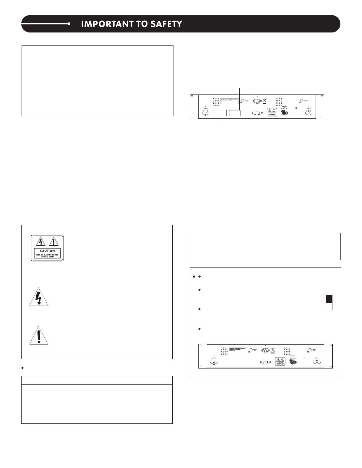
RATING LABEL
CAUTION:
1. Handle the power supply cord carefull y
Do not d ama ge or de for m the po wer su ppl y cord.
If i t is damaged or d eformed, it m ay cause elec tric
shock o r malfunction whe n used. When r emovi ng
from wall out let,be sure to rem ove b y hol ding the
plug attachment and not by pulling the cord.
2. I n ord er to p reven t elect ric sho ck, do not open the
top cover. If a problem occurs, contact your dealer.
3. D o not place metal obj ects or spill liqui d inside the
CD player. Electric shock or malfunction may result.
Pleas e, re cord and r etain the Model na me an d ser ial
number of your set shown on the rating label .
Model No. ___________ Serial No. _ __ __ __ __ __
CAUTION: TO REDUCE THE RISK
OF ELECTRIC SHOCK, DO NOT
REMOVE THE COVER (OR BACK) .
TH ERE ARE NO SERVICEABLE
PARTS INSIDE.
REFER SERVICING TO QUALIFIED SERVICE
PERSONNEL.
Th e lightning flash with arrowhea d sy mb ol ,
within an equil ateral triang le, is intended t o
alert the user to the presence of uninsulate d
“da n ger ous vol tage " w ithi n t he prod uct' s
encl o sure tha t m a y b e of suf fici e n t m agni tud e to co nstit ute a r isk o f elect ric s hock
t o p ers o ns.
The exclamation point w it hin an equilateral
trian gle i s int end ed to aler t the user to t he
p r e s e n c e o f i mp o r t a n t oper a t i n g and
ma intenance (servicing) instructions in the
literature ac companyin g the appliance .
CLASS 1 LABEL
CAUTION:
USE O F CONTROLS O R A D J U S T M E N T S OR
RE FORMANCE OF P ROCEDURES O THER THAN
T H O S E S P E C I FI E D HE R E I N M AY R E S U LT IN
HAZARDOUS RADIATION EXPOSURE.
TH E COMPACT DISC P LAYER SHOULD N OT BE
ADJU ST ED OR REPAI RED BY ANYONE EXCEPT
PROPERLY QUALIFIED SERVICE PERSONNEL.
DOUBLE INSULATED - WHEN SERVICING , USE
ONLY IDENTICAL REPLACEMENT PARTS.
NOTE:
This unit may cause interference to radio and television
reception.
Lin e Vo ltage Sele ction (for mu lti ple
voltage model only)
The desired voltage may be set with the
VOLTAGE SELECTOR switch on the rear
panel, using a screwdriver.
Do not twist t he VOLTAGE SELECTOR
sw itch with excessi ve force as this may
cause damage
If the VOLTAGE SELECTOR switch does not move
smoothly, please contact a qualified serviceman.
115V
230V
FOR U.S.A. & CANADA MODEL ONLY
CAUTION
TO PREVENT ELECTRIC SHOCK DO NOT USE
THIS (POLARIZED) PLUG WITH AN EXTENSION
CORD, RECEPTACLE OR OTHER OUTLET UNLESS
THE B L A D E S CA N BE F U L LY INSERT E D TO
PREVENT BLADE EXPOSURE.
2
Page 4

NOTE ON U SE
Allow for sufficient heat dispersion when installed in a rack.
•
Handle the power cord carefully.
Hold the plug when unplugging th e co rd .
•
Keep the set free from moisture, water, and dust.
•
Unplug the power cord when not using the s et f or l on g pe ri od s of t im e.
•
Do not obstruct the ventilation holes. (For se ts w it h ve nt il at io n ho les.)
•
Do not let foreign objects in the set.
•
Do not let insecticides, benzene, and th in ne r co me i n co nt ac t wi th t he set.
•
Never disassemble or modify the set in any w ay.
•
For 220 volt use in USA, USA nema style 220 volt plug . Fo r ot he r co un tr ie s, u se p ro per plug for the local outlet.
MAIN FE AT URES
(1) 8 times oversampling 1 bit D/A converte r.
(2) 4 different scan speeds.
(3) Frame search.
(4) Auto cue.
(5) 20 sec Anti-shock.
(6) Pitch display.
(7) MP3 playback.
MAIN UNIT
2 3
5 7 4 5
1
2
6
(1)POWER
(2)DISC HOLDER
(3)OPEN/CLOSE
(4)REMOTE CONTROL CONNECTOR
(5)AUDIO OUT L AND R
(6)DIGITAL OUT SOCKET
(7)VOLTAGE SELECTOR (FOR DUAL VOLTAGE
ONLY)
3
Page 5
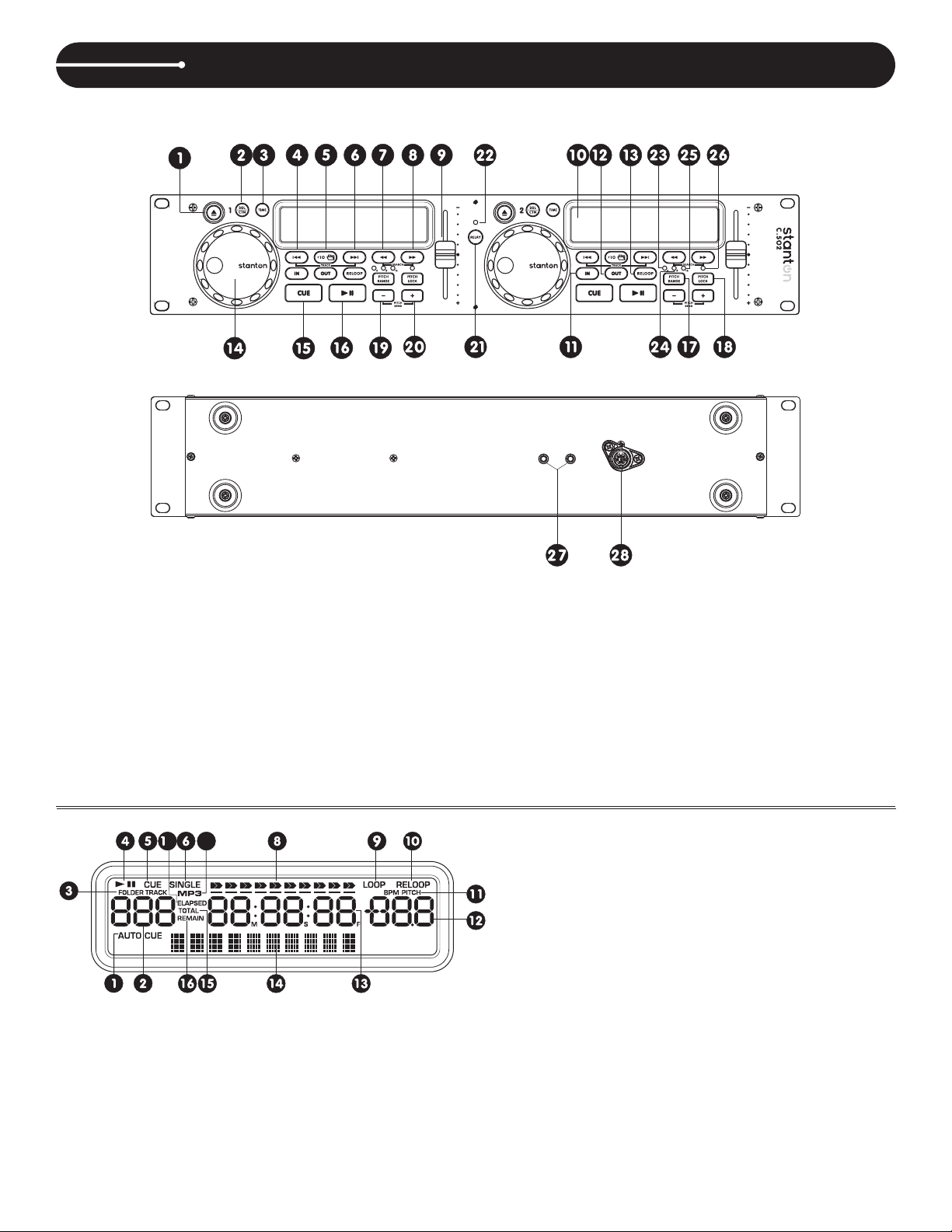
CONTROL UNIT
MAIN FE AT URES
//
(1)OPEN/CLOSE
(2)SINGLE/CONTINUE
(3)TIME
(4)TRACK BACKWARD
(5)+10/FOLDER
(6)TRACK FORWARD
(7)F. BACKWARD
(8)F. FORWARD
(9)PITCH SLIDER
(10)LCD
7
7
(1)AUTO CUE
(2)
TRACK INDICATOR
(3)FOLDER/TRACK INDICATOR
(4)PLAY/PAUSE INDICATOR
(5)CUE INDICATOR
(6)SINGLE INDICATOR
(7)MP3 INDICATOR
(11)LOOP IN
(12)LOOP OUT
(13)RELOOP
(14)JOG WHEEL
(15)CUE
(16)PLAY/PAUSE
(17)PITCH RANGE
(18)PITCH LOCK
(19)PITCH DOWN
(20)PITCH UP
(21)RELAY
(22)RELAY LED
(23)PITCH 4% LED
(24)PITCH 8% LED
(25)PITCH 16% LED
(26)PITCH LOCK LED
(27)FADER START CONNECTOR
(28)CONTROL CONNECTOR
TIME BAR INDICATOR
(8)
(9) LOOP INDICATOR
(10)RELOOP INDICATOR
(11) PITCH INDICATOR
(12)PITCH METER
(13) TIME DISPLAY
(14) CHARACTER DISPLAY
(15) TOTAL REMAIN INDICATOR
(16) REMAIN INDICATOR
(17) ELAPSED INDICATOR
4
Page 6

1. Checking the Contents
Check that the carton contains the following i te ms :
1) Main unit
2) Control unit
3) Operating instructions (this booklet)
4) Two pair of RCA pin cord.
5) Control cords (1 meter)
6) Power cord
7) Two fader start cables
2. Installing the Unit
Mount the unit onto your console or rack with 19" EIA rac k
rails.
CAUTION:
The player will work normally when the main unit is
mounted with the front panel at within 15 degree s of t he
vertical plane. If the unit is tilted excessively, discs may
not be loaded or unloaded properly.
Max
15
The control panel's LCDs are designe d to b e
clearly visible within the angle s sh ow n in F ig ur e 2.
Mount the control unit so that the visual angl e is
within this range.
45
5
Main unit
Control
Panel Button
Figure1 Figure2
Connections
1) Turn off the POWER switch.
2) Connect the RCA pin cord to the input on your mi xe r.
3) Connect the control cords to the REMOTE conne ct or o n th e ma in u ni t.
CAUTION:
Be sure to use the supplied control cords. Usi ng a no th er t yp e of c ab le m ay result in damage.
Be sure the power is off when connecting the control cords. Otherwise the units may not work properly.
NAMES A ND FUNCTIO NS
Main Unit Front Panel
(1) POWER (Power ON/OFF Switch)
When t he POWER switch is pressed , the power
turns on.
(2) DISC HOLDER
Place th e dis cs in the holder . P ress the O PEN /
CLOSE butto n to open a nd close the disc ho lder.
(3) OPEN/CLOSE
Pre ss it to ope n and cl ose th e d isc ho lde r . T he
con tro l unit a lso in clu des OPEN/CLOSE bu tto n.
The disc holder cannot be opened during playback,
so stop playback before pressing the button.
(4) REMOTE CONTROL CONNECTOR
Connect this connector to the control unit using
the included control cord.
(5) AUDIO OUT
Th e audio s ignal s from each pl ayer ar e outpu t
from these jacks.
(6) DIGITAL OUT SOCKET
The music signal of this socket is digital. Connect
the output to the respective digital input of a digital
amplifier for example.
5
Page 7

Control Unit
NAMES A ND FUNCTIO NS
(1)OPEN/CLOSE
Press it to open and close the disc holder. The main
unit also includes OPEN /CLOS E buttons. The dis c
hol der ca nno t be ope ned during pla yba ck, so stop
playback before pressing the button.
(2) SGL/CTN (Single/Continuous Button)
Press it to switch between the single and continuous
pla y mod es. The SI NGLE mod e is indicate d by the
SINGLE indicator on the LCD
(3)TIME CD MODE
Press th is bu tto n to switc h the time display among
the elapsed time and remaining time and tota l
remaining time of the disc.
(4)TRACK BACKWARD
Use thi s butto n to go b ack to th e begin ning of t he
curre nt tr ack or selec t a previous trac k for play ing.
(5)+10/FOLDER
C D m ode use th is but ton to ski p a hea d 1 0 t rack s.
Mp3 mode press this button to select the next folder.
(6) TRACK FORWARD
Use this button to skip to the next CD track.
(7).(8)F.FORWARD/F.BACKWARD
Press these buttons to perform scan function during
pause mode or during play mode.
(9) PITCH SLIDER
Use the slider to adjust the CD pitch . Slide up to
decrease pitch, down to increase pitch.
(10) LCD
(11) LOOP IN
Used for setting a start loop point and releasing the
loop action.
(12) LOOP OUT
Used for setting the end loop point and releasing the
loop action.
(13) RELOOP
Depending on mode, as explained further, this button
is used for e ither r epeatin g a previou sly set l oop or
seamlessly stuttering on the last set cue point.
(14)JOG WHEEL
When the dia l is turned durin g CD pause , the
point at which the sound is being produced mov es
by a number of frames corresponding to the number
of clicks.
Clockwise moves the point forward, counterclockwise
moves the point backward.
(15)CUE (Cue Button)
Press the CUE button during playback to return to
the position at which playback started.
(16)PLAY/PAUSE
Use this button to start playback. Press once to start
playback , once again to set the pause mode , and
once more to resume playback.
(17)PITCH RANGE
Choose from pitch percentages of 4%,8% and 16%.
(18)PITCH LOCK
Use this button to enable or disable BPM adjustment
with the pitch sliders. BPM adjustment with the pitch
sliders is enabled when the PITCH LED lights.
(19)PITCH DOWN
Th e CD slows do wn wh ile t his butt on is pressed .
Rel ease the b utt on to return to th e ori gin al BPM.
(20)PITCH UP
The CD speeds up while this button is
pressed. Release the button to return to the
original BPM.
(21)RELAY
Press this button when Disc 1 ends the CD player
will automatically change to Disc 2 and when D is c
2 ends it will return to Disc 1,etc.
(22)RELAY LED
(23)PITCH 4%LED
(24)PITCH 8% LED
(25)PITCH 16% LED
(26)PITCH LOCK LED
(27)FADER START
Via the Contr ol socket, the res pective C D-playe r
can be remotely controlled. If you are using a mixer
with fader s tart- function c onnect the play er with
the Con tro l O ut- so cket . P leas e note th at the se
sockets must never be connected with any voltage.
(28)CONTROL CONNECTOR
Connect this connector to the REMOTE connector
on the main unit using the included control co rd .
6
Page 8

CONTR OLS AND FUNC TIONS
7
1. AUTO CUE
This will indicate if the Auto Cue is on or off. Press
and hold the SGL/CTN for 1 sec. to turn the Auto Cue
function on and off.
2.TRACK INDICATOR
This 3-digit indicator displays the cu rr en t tr ac k. The
number displayed in the track indicato r is a d ir ec t
reference to a track being selected or a track in pl ay,
pause, or cue mode.
3.FOLDER/TRACK INDICATOR
This indicator shows you if you are looking at the
track number or the folder number.
4.PLAY / PAUSE INDICATOR
When the unit is in play mode the “PLAY”indicator
will glow, when the drive is in pause mode the “PAUSE”
indicator will glow.
5.CUE INDICATOR
This indicator will glow when the unit is in CUE mode
and will flash every time a new CUE POINT is set.
6.SINGLE INDICATOR
This indicates that the CD drive is in single play mode.
The track will play once and return to CUE mode. If
the single indicator is not on, the unit is in continuous
mode and the drive will play all the remaining tracks
on the disc until you stop it or power is interrupte d.
7.MP3 INDICATOR
This will indicate that a Mp3 disc is loaded in the drive.
8.TIME BAR INDICATOR
This bar gives a visual approximation of a track's
or disc's remaining time. This bar will begin to flash
when a CD is ending or a track if the unit is in"
SINGLE" mode.
7
9.LOOP INDICATOR
Appears when the CD is repeating a particular area
with the music on the CD.
10.RELOOP INDICATOR
Appears when the CD has a loop set previously
and can go back loop again.
11.PITCH INDICATOR
Indicator will light up when the Pitch is ac ti va te d.
12.PITCH METER
Shows the percentage change in pitch of the song.
The meter will display the pitch percentage applied
by the PITCH SLIDER.
13.TIME DISPLAY
This displays the Minutes, Seconds, and Frames.
The meter will display either the elap se d ti me , or
remaining time of a track.
14.CHARACTER DISPLAY
This will display the name of the file, artist, and title
when a Mp3 disc is loaded.
15.TOTAL REMAIN INDICATOR
When TOTAL and REMAIN are visible, this indicates
that the Time Display is showing total remaining
disc time.
16.REMAIN INDICATOR
When the REMAIN indicator is visible this indicates
that the Time Display is showing remaining track
time.
17.ELAPSED INDICATOR
It is for showing time as it is taking place.
7
Page 9

1. Opening and Closing the Disc Holder
Turn the unit power on . Press the OPEN/CLOSE button to open the di sc h ol de r. O PE N/ CL OS E bu tt on s are
provided on both the main unit and control uni t.
The disc holder cannot be opened during playback to prevent playback from being interrupted if the OPEN/CLOSE
button is pressed accidentally. Stop the playback first, then press the OPEN/CLOSE button.
2. Loading discs
Hold the disc by the edges and place it in the disc ho ld er, t he n pr es s th e
OPEN/CLOSE button again to close the disc holder. The unit will show the total
track number and the total playing time for about 2 se co nd s th en e nt er t he c ue
condition, the cue point will be set to the music star ti ng p oi nt o f th e fi rs t tr ac k
automatically.
CAUTION:
Do not place any foreign objects in the disc holde r, an d do n ot p la ce m or e th an one disc in the disc holder at a
time.
Do not push the disc holder in manually when the p ow er i s off, as this may result in malfunction and damages
the player.
3. Selecting Tracks
Press the SKIP button once to move to the next higher or lower track.
Hold the SKIP button to change tracks continuously at a higher speed.
When a new track is selected during playback , playback begins as soon as the skip search operation is completed.
If the skip button is pressed while at the last track, the first track is sele ct ed . I n th e sa me w ay, if the skip
button is pressed while at the first track, the last track is se le ct ed .
4. Starting Playback
Press the PLAY/PAUSE button during the pause or cue condition to start playback. The PLAY indicator will light.
The point at w hich playback starts is a utomatically stored i n the memory as the cue poi nt . The p ickup then
returns to the cue point when the CUE button is presse d. ( Ba ck C ue )
Figure 2-1
5. Stopping Playback
There are two ways to stop playback.
1. Press the PLAY/PAUSE button during playback to pause at that point.
2. Press the CUE button during playback to return to the c ue p oi nt a nd e nt er p au se c ondition.(Back Cue)
Figure 4-1
CUE
Figure 5
8
Page 10

6. Pausing
Press the PLAY/PAUSE button to switch between play and pause.
The play indicator flashes when the pause mode is set.
Figure 6 show the relationship between the p la y an d pa us e.
6
2
4
3
1
5
7
Figure 6
1
The player has completed the cue or pause op er at io n
and is waiting for the play start command.
2
When the PLAY/PAUSE button is pressed and enter
play mode is entered.
3
Playing.
4
The pause mode is set when the PLAY/PAUSE button
5
Pausing.
6
Playback resumes when the PLAY/PAUSE button
is pressed again.
7
Playing.
is pressed again.
7. Cueing
"Cueing" is the action of preparing for play ba ck .
Press CUE button, the player will enter cue mode , th e pl ay ba ck r et ur ns t o cu e po int and enter pause condition,
the cue indicator l igh ts up and the play in dic ator fla she s. Wh en PLAY/PAUSE bu tton is pressed, pl ay st art s
from the cue point.
Wh en the track search operat ion is comple ted after pre ssing the SKIP butt ons, the play er automatica lly finds
the position at which the sound starts and cues ther e( Au to C ue ).
If the C UE button is pressed after the se ar ch operation or the scanning op er ation, the playback returns to cu e
point and enters pause condition.
Figure 7-1 shows the relationship betwee n th e pl ay a nd b ac k cu e op erations.
2
3
1
1
The player has completed the cue or pause op er at io n
9
8
2
3
1
and is waiting for the play start command.
2
When the PLAY/PAUSE button is pressed, playback
starts and the cue point is stored in the memory.
3
Playing.
4
The pause mode is set when the PLAY/PAUSE button
4
6
7
5
5
6
7
8
9
9
Pressed again.
is
Pausing.
When the PLAY/PAUSE button is pressed again;
Playing.
Press the CUE button.
The pickup returns to the cue point.(Back Cue)
8
Figure 7-1
Cue point setting:
Wh en play start s from pause by pressing t he IN button or S canning or Frame Searc h; also skip to a n ew track
by using skip button, the begin play poi nt w il l be s et t o th e ne w cu e po in t.
When a new cue point is set, the cue indicator lig ht s by f la sh f or a bo ut 1 s ec on d.
NOTE: During cue mode, if the CUE button is pressed and hold, playback will start from the cue point, when the
button is released, the player will retu rn t o th e cu e mo de a ut om at ic ally, it allows you to check the cue point.
8. Jog Wheel - The jog wheel serves two functions depending on the current operating mode:
The jog wheel will act as a slow frame search co nt ro l wh en t he u ni t is i n pa use or cue mode allowing you to set
a specific cue point or find a particular star ti ng p oi nt .
The w hee l also w ork s as a mom ent ary pitch b end during pla yba ck . Turn ing the whe el clockwise w ill
in cr ease the pitch perc entage up to +16%, an d turning the wheel i n the counterclockw ise direction will
decrease the pitch percentage up to -16% . The pitch bend will be determined by how fast you turn the wheel.
9
Page 11

9. Scanning (Fast forward/Fast backward)
Scanning is a function for moving quickly forw ar d or b ac kw ar d wh en t he o r bu tt on i s pr es sed.
The scanning speed depends on how long you hold the button.
Press and hold the or to begin scanning. The disc moves rapidly forward or backward and the sound is
output. The current scan point is indicated on the LCD.
Press and hold the to scan in the forward scanning, to scan in the rev er se s ca nn in g.
10. Time display
MP3 MODE
Press the TIME button to select time display MP3 mode:
1
Elapsed time of a track.
2
Remaining time of a track.
ELAP SED
REMA IN
Figure 10-1
CD MODE
Press this button to switch the time display
It switches between the elapsed time and rem ai ni ng t im e an d to ta l re maining time of the disc.
ELAP SED
TOTAL
REMA IN
REMA IN
Figure 10-2
11. Matching the Beats Per Minute (BPM)
There are two tools available for matching the BPM of the two CDs:
1
Use the pitch slider to adjust the BPM statically.
2
Use the PITCH BEND buttons to change the BPM temporarily.
Use the JOG WHEEL to change the BPM temporarily.
1)Pitch Slider
1
To adjust the BPM by sliding the pitch slider up or down, press the PITCH butto n to t ur n on t he P IT CH
adjustment function before use.
2
Slide the pitch slider up to decrease BPM, or down to increa se B PM . The adjustment range is +/-4%,+/-8%
+/-16%
2)Pitch Bending
The BPM increases or decreases respectively while the PITCH BEND+ or PITCH BEND- button is pressed.
The BPM increase depends on how long you hold the button. If you hold the button for about 1/2 second,
the BPM wil
l go either to +16% for PITCH BEND+ or -16% for PITCH BEND-. If you tap the bu tt on , th e
BPM will only change a little so you can change the beat sligh tl y wi th ou t au di bl e ch anges in the music.
The CD will return to the tempo indicated by the Pitch slider when you let go of the PITCH BEND+ or -.
Figure 11-1 shows an example of how to use the pitch bend function . In this example , both players are
playing and the
BPM has already been matched with the pitch sliders.
The bass beats also match
CD1
bass beat
CD2
bass beat
bass beat
bass beat
10
PIT CH BEND
Page 12

12. Fader start
You have the possibility to start the respective C D pl ay er d ir ec tl y fr om t he m ixer. Make sure that the Control
socket is connected with the respective socket on the mi xe r. Add it io na ll y, the Audio out sockets have to be
connected with the Line input sockets of your mixer. Pl ea se n ot e th at t he F ad er s ta rt f un ct ion only works
with the appropriate mixers. Insert the CD and select the de si re d tr ac k. S ta rt p la yb ack from your mixer.
13. Relay
In the Relay operation, the device automatical ly s wi tc he s to t he o th er p la ye r after every track. In this way,
you have the possibility to enlarge the music prog ra m by u si ng s ev er al C Ds.
To start, press the Relay button. Press the Single b ut to n (t he d is pl ay s ho ws “ S IN GLE” ) on both CD players.
Start playback of CD1. As soon as the current track o f CD 1 is f in is he d, t he p la ye r automatically starts CD2.
The first CD player goes into Pause-mode . Pr es s th e si ng le b ut to n ag ain for continuous mode (the “SINGLE”
display is not lit). When playback of all trac ks o f CD 1 is f in is he d, t he p la yer automatically starts CD2 and Cd1
is goes into pause-mode.
You can load a new CD or memorize a Cue point for either player in the Pause Mode.
When playback of all tracks or the current track of CD 2 is f in is he d, t he p la ye r au tomatically starts CD1 and
CD2 goes into pause-mode.
CAUTION: The Relay operation does not work properly if the two CD players are connected to different power
amplifiers.
11
Page 13

BEFOR E SWITCHIN G OFF THE POWE R
When you have finished using the CD play er, b ef or e sw it ch in g off the power, be sure that the disc holder had been
closed with the OPEN/CLOSE button.
CAUTION:
Do not forcibly close the disc holder when t he p ow er i s off.
PWER OFF PWER OFF
Do not switch off the power when the disc holder is open.
COMPACT D ISCS
1. Precautions on handling compact dis cs
Do not allow fingerprints, oil or dust to get on the
surface of the disc.
If the disc is dirty, wipe it off with a soft dry cloth.
Do not use benzene, thinner, water, reco rd s pr ay,
electrostatic-proof chemicals, or sili co ne -t re at ed
cloths to clean discs.
Always handle discs carefully to preve nt d am ag in g
the surface; in particular when removing a dis c fr om
its case or returning it.
Do not bend the disc.
Do not apply heat.
Do not enlarge the hole in the center of the dis c.
Do not write on the label (printed side) with a ha rd tipped implement such as a pencil or ball po in t pe n.
Switch off the power after the disc holder has been
closed with the OPEN/CLOSE button.
Condensation will form if a disc is brought into a
warm
area from a colder one, such as outdoors in winter.
Do not attempt to dry the disc with a hair dryer, etc.
2. Precaution on storage
After playing a disc, always unload it from the player.
Always store the disc in the jewel case protect from
dirt or damage.
Do not place discs in the following areas:
1
Areas exposed to directs sunlight for a considerable
time.
2
Areas subject to accumulation of dust or high
humidity.
3
Areas affected by heat from indoor heaters, etc.
SPECI FIC ATI ONS
GENERAL
Dimensions: Main unit: 482(W) x 88.8(H) x 251(D) mm
19” (W) x 3 1/2” (H) x 9 4/5” (D)
Control unit: 482(W) x 88.8(H) x 60(D) mm
19” (W) x 3 1/2” (H) x 2 1/3(D)
Weight: Player unit: 5.3 kgs / 11.7 lbs
Control unit: 1.8 kgs / 3.9 lbs
Power supply: Dual Voltage:
AC 115/230V, 50/60Hz
Single Voltage:
AC 100V, 50/60Hz (For Japan)
AC 110V, 60Hz (For Taiwan)
AC 120V, 60Hz (For U.S.A.,Canada,Mexico)
AC 220V, 50Hz (For United Arab Emirates,Chile,Aegentina)
AC 220V, 60Hz (For Philippines)
AC 230V, 50Hz (For Europe,New Zealand,South Africa,Singapore,Israel)
AC 240V, 50Hz (For Australia,U.K)
Power consumption: 25W
12
Page 14

WAR RANTY & RETU R N POLICY
WARRANTY & RETURN POLICY
Warranty
Through Stantons authorized dealers around the World, Stanton, or one of Stantons authorized distributors outside the U.S., will, without charge, repair
or replace, at the sole discretion of the entity responsible for making the repair or providing the replacement, any Stanton merchandise proved defective
in material or workmanship for a period of one (1) year following the date of original purchase. Exceptions to this warranty are as noted below:
The warranty for mechanical parts which are subject to wear and tear are limited to the earlier of either thirty (30) days following the date of original
purchase or the following number of cycles: Faders - 15,000; Rotary potentiometers - 10,000; and Switches - 10,000.
Stanton will warrant all replacement parts and repairs for ninety (90) days from the date of original shipment. Repairs made necessary by reason of mi use, alteration, normal wear, or accident are not covered under this warranty.
Returns
Authorized Stanton dealers are only authorized to sell and distribute merchandise within a specific country. All goods requiring warranty repair or replacement must be returned (freight prepaid if not hand-delivered) to the authorized Stanton dealer from whom the merchandise was purchased and in the
same country where the merchandise was purchased. For purposes of purchases made via the Internet, the merchandise must be returned to the authorized Stanton dealer in the country where the authorized Stanton dealer which sold the merchandise to purchaser is located and not the authorized Stanton
dealer in the country where the purchaser is located or the country in which the merchandise was received. Any returns to a non-authorized dealer or to
an authorized Stanton dealer not in the same country as the merchandise was intended to be sold or as set forth above will void this warranty.
To initiate a warranty repair, you must contact the authorized Stanton dealer from whom you purchased the merchandise, and follow such authorized
Stanton dealers return policy.
Stanton assumes no risk and shall be subject to no liability for damage or loss resulting from the specific use or application made of the merchandise.
Stantons liability for any claim, whether based on breach of contract, negligence, infringement of any rights of any party, or product liability, and relating
to the merchandise shall not exceed the price received by Stanton from our purchase of such merchandise. In no event will Stanton be liable for any
special, incidental or consequential damages (including loss of use, loss of profit and claims of third parties) however caused, whether by the negligence
of Stanton or otherwise. To the extent permitted by law and except as otherwise provided above, Stanton disclaims any express or implied warranties of
merchantability or fitness for a particular purpose.
The above warranty provides you with specific legal rights. You may also have additional rights, which are subject to variation from state to state and
country to country.
If there is a dispute regarding the warranty of merchandise that does not fall under the warranty conditions stated above, please include a written explanation with the merchandise when returned pursuant to the terms and conditions set forth herein.
Please register your product online at www.stantondj.com.
 Loading...