

Page 1
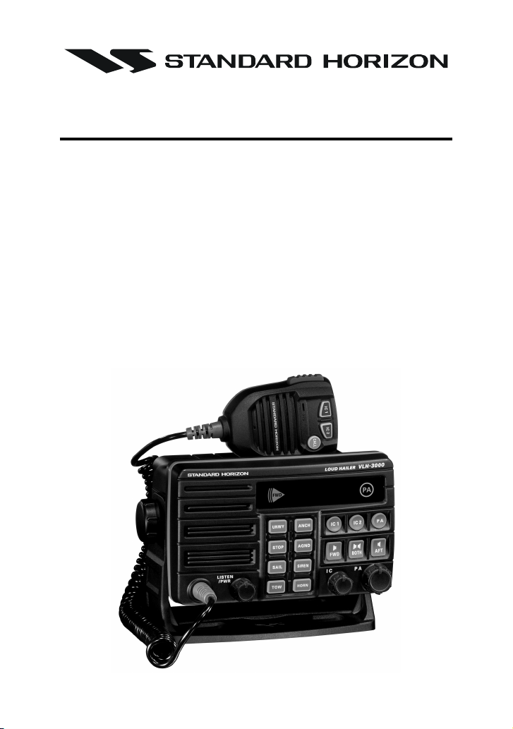
VLH-3000
30 Watt Loud Hailer
Owner's Manual
Four Fog Horns, Bells and Whistles
New Conmetic Design for a Consistent Look with other Standard
Horizon Products
Flush Mount Capability
Two 30 Watt PA Outputs, One Forward One After
Two Intercom Connections Allow You to Toggle Between IC 1 and IC2
Microphone Features Dedicated Button for Access to Intercom Sta-
tions
External Speaker Output: 4 W Max. at 4 ohm
VLH-3000 Page 1
Page 2

TABLE OF CONTENTS
1 GENERAL INFORMATION .................................................................. 3
2 PACKING LIST .................................................................................... 4
3 OPTION ................................................................................................ 4
4 INSTALLATION .................................................................................... 5
4.1 Optional MMB-84 Flush Mount Installtion ..................................... 5
4.2 Electrical Installation ..................................................................... 6
5 CONTROLS AND SWITCHES ............................................................. 8
6 OPERATION ...................................................................................... 10
6.1 Switching Power On/Off .............................................................. 10
6.2 Hail/Listen Back .......................................................................... 10
6.3 Intercom ...................................................................................... 11
6.4 Automatic Signaling..................................................................... 12
7 FOG ALERT TONE FREQUENCY .................................................... 14
8 MAINTENANCE ................................................................................. 16
8.1 Replacement Parts ...................................................................... 16
8.2 Factory Service ........................................................................... 17
8.3 Troubleshooting Chart................................................................ 17
9 WARRANTY....................................................................................... 18
10 SPECIFICATIONS.............................................................................. 22
VLH-3000Page 2
Page 3

1 GENERAL INFORMATION
The STANDARD HORIZON VLH-3000 is a marine Loud Hailer that operates as a multifunction unit. It has three modes:
Hail/Listen-Back
Intercom
Automatic Signalling
In the Hail/Listen-Back mode, the Loud Hailer can send amplified audio
signals to a PA horn and then listen back for signals coming in from the PA
horn.
In the Intercom mode, the Load Hailer can have private conversations with
up to two MLS-300i intercom stations.
In the Automatic Signaling mode, the Loud Hailer can send different kinds
of signals used mostly to alert nearby vessels to the presence and approximate position, and to indicate the vessel’s status or maneuverability limitation.
Your Loud Hailer requires 13.8 VDC (±20 %) power input. The VLH-3000
maximum PA speaker output is 30W.
ON-LINE WARRANTY REGISTRATION
Please visit www.standardhorizon.com to register the VLH-3000 Loud
Hailer. It should be noted that visiting the Web site from time to time
may be beneficial to you, as new products are released they will appear
on the STANDARD HORIZON Web site.
PRODUCT SUPPORT INQUIRIES
If you have any questions or comments regarding the use of the VLH3000, you can visit the STANDARD HORIZON Web site to send an E-
Mail or contact the Product Support team at 800-767-2450 M-F 7:005:00PST.
VLH-3000 Page 3
Page 4

2 PACKING LIST
When the package containing the Loud Hailer is first opened, please check
it for the following contents:
VLH-3000 Loud Hailer (with Microphone)
Mounting Bracket (with attaching hardware and hanger kit)
Owner’s Manual
Power Cord
Dust Cover
3 OPTIONS
MMB-84 ...................................................................... Flush-Mount Bracket
MLS-300i ......................................................................... Intercom Speaker
MLS-300 ................................................................... External Loudspeaker
MLS-310 ........................................................... Amplified External Speaker
101W ...................................................................... White External Speaker
220SW .................................................................. 4.5” Round Hail/PA Horn
240SW ..................................................... 5” x 8” Rectangular Hail/PA Horn
VLH-3000Page 4
Page 5
4 INSTALLATION
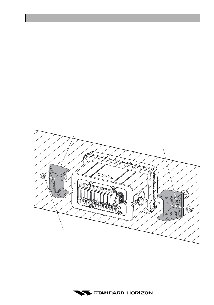
4.1 Optional MMB-84 Flush Mount Installation
1. To assist in flush mounting, a template has been included. Use this template to find the mounting location.
2. Use the template to mark the location where the rectangular hole is to be
cut. Confirm the space behind the dash or panel is deep enough to accommodate the VLH-3000 (at least 4.5 inches or 11.5 cm deep).
There should be at least 1/2 inch (1.3 cm) between the VLH-3000’s
heatsink and any wiring, cables or structures.
3. Cut out the rectangular hole and insert the VLH-3000.
4. Fasten the brackets to the sides of the VLH-3000 with the lock washer
nut combination; so that the mounting screw base faces the mounting
surface (see Figure 1).
5. Turn the adjusting screw to adjust the tension so that the VLH-3000 is
tight against the mounting surface.
Bracket
Adjusting Screw
Lock-washer nut combination
Figure 1. MMB-84 Flush Mount Installation
VLH-3000 Page 5
Page 6
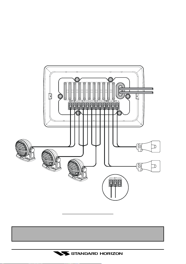
4.2 Electrical Installation
The rear panel of the VLH-3000 contains:
A DC Power Cord
A terminal strip for the External Speaker, two PA Horns, and two MLS-
300i Intercom Speakers.
Refer to Figure 2 and complete the following steps for the electrical installation.
POSITIVE
POSITIVE
NEGATIVE
NEGATIVE
YELLOW
YELLOW
WHITE
WHITE
BLACK
WHITE
BLACK
BLACK
PA Ho rn
External Speaker
Intercom Speaker
Intercom Speaker
BLACK
Detail “A”
WHITE
PA Ho rn
Figure 2. Electrical Connections
NOTE
The terminal strip is not waterproof. Care needs to be taken when installing so it is not directly exposed to the elements.
VLH-3000Page 6
Page 7

1. Use the supplied Power Cord assembly for power connection. Connect
the red wire to the “Positive (+)” terminal, and the black wire to the “Negative (–)” terminal of the power source.
CAUTION
Reverse polarity connections will damage the VLH-3000
2. Use #22 AWG (or larger) stranded, plastic-jacketed wire to connect the
PA Horns (“FWD” and “AFT” terminals) and Intercom Speakers (“IC1”
and “IC2” terminals).
3. An external 4-Ohm 6 W speaker may be connected (“EXT SP” terminal),
if desired.
4. For the PA Horn, it is recommended that a 4-Ohm 30 W horn speaker be
used. Also note that an 8-Ohm speaker may be used, but the loudness
will be reduced.
5. The VLH-3000 can use the optional MLS-300i Intercom Speaker. This is
connected to any of the Intercom terminals (“IC1” or “IC2”).
6. See Detail “A” in Figure 2, If a 2-wire speaker (such as a MLS-300 External Speaker) is connected to the Intercom terminals (“IC1” or “IC2”), the
positive wire should be connected to the center terminal and negative
wire should be connected to the left-hand terminal. Do not connect the
any wire to the right-hand terminal! If you connect one of the wires of
a 2-wire speaker to a right-hand terminal, the speaker will beep continuously when turned on.
7. Put the supplied Protection Cover to the terminals to avoid a short circuit.
VLH-3000 Page 7
Page 8
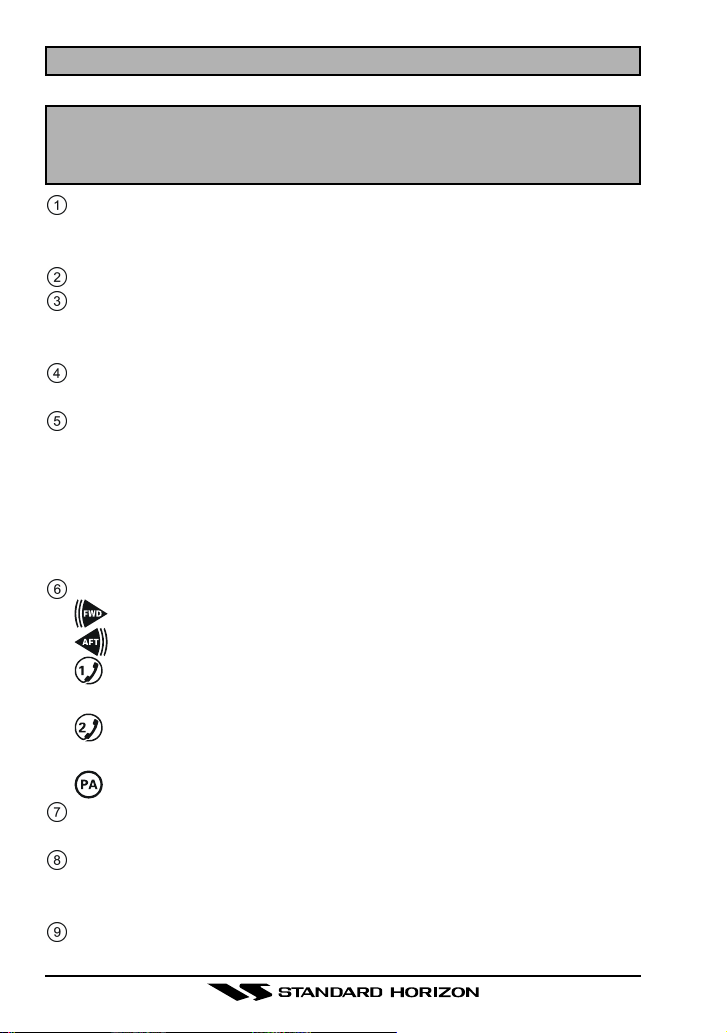
5 CONTROLS AND SWITCHES
NOTE
This section defines each control of the Loud Hailer. See Figure 3 for
location of controls. For detailed operating instructions refer to section
“6 OPERATION.”
LISTEN/PWR Knob
Turns the VLH-3000 on and off as well as adjusts the volume level of the
built-in speaker or external speaker in the LISTEN-BACK mode.
AUTOMATIC SIGNALING Buttons
IC Knob
Adjusts the volume level of the Intercom Speaker in the INTERCOM
mode.
PA Knob
Adjusts the PA horn level in the HAIL or AUTOMATIC SIGNALING mode.
KEYBOARD
IC 1 - Activates the Intercom Speaker 1.
IC 2 - Activates the Intercom Speaker 2.
PA - Activates the PA horn.
FWD - Activates the Forward (Front) PA horn.
BOTH - Activates the both Forward (Front) and Aft (Rear) PA horns.
AFT - Activates the Aft (Rear) PA horn.
DISPLAY
- Indicates the Foward (Front) PA horn is selected.
- Indicates the Aft (Rear) PA horn is selected.
- Steady: Indicates Intercom Speaker 1 is selected.
Blink: Intercom 1 is calling the VLH-3000.
- Steady: Indicates Intercom Speaker 2 is selected.
Blink: Intercom 2 is calling the VLH-3000.
- Indicates the PA horn is selected
INTERNAL SPEAKER
Provides audio from intercom speakers or PA Horn.
INTERCOM Buttons
IC 1 - Activates the Intercom Speaker 1.
IC 2 - Activates the Intercom Speaker 2.
PTT Button
Activates the microphone.
VLH-3000Page 8
Page 9

Figure 3. Controls and Switches
MICROPHONE
Speak into the Mic while the PTT button is press to transmit audio to the
PA horn or the Intercom Speaker.
CALL Button
Used only when a Intercom Speaker is connected to IC1 or IC2. When
pressed produces a beep in the connected Intercom Speaker.
VLH-3000 Page 9
Page 10

6 OPERATION
This section contains operating instructions for the VLH-3000.
6.1 Switching Power On/Off
1. Rotate the LISTEN/PWR knob clockwise to turn on the VLH-3000.
2. To turn the VLH-3000 off, turn the LISTEN/PWR knob fully counter-clockwise.
6.2 Hail/Listen-Back
1. Press the PA button to activate the PA horn, then select the output PA
horn by pressing the FWD, BOTH, or AFT button.
2. Adjust the LISTEN/PWR knob to approximately 10 o’clock position, if
necessary turn clockwise to increase the internal (or external speaker
when connected) speaker volume.
3. Adjust the PA knob to approximately 10 o’clock position.
4. Press the microphone PTT button, then speak clearly with your mouth
about one inch (2.5 cm) from the microphone. Rotate the PA knob with
the PTT button pressed to adjust the PA horn output level. The PA horn
output level can be set from 0 to 30 watts.
5. Release the microphone PTT button. The PA horn will automatically act
as a microphone and the incoming audio signal will be heard from the
built-in or external VLH-3000 speaker. This is called Listen-Back.
6. Rotate the IC knob to increase or decrease the Listen-Back volume.
VLH-3000Page 10
Page 11

6.3 Intercom
To use the Intercom feature of the VLH-3000, optional Intercom Speaker
are necessary. The following are available from your Dealer:
MLS-300i - Intercom Speaker with PTA (Push To Alert)
1. To activate the Intercom Speaker(s), press the following keys:
IC1 - to activate Intercom Speaker 1
IC2 - to activate Intercom Speaker 2
2. Make sure the VLH-3000 is in the HAIL mode, and press the microphone PTT button. Speak clearly with your mouth about one inch (2.5
cm) from the microphone.
3. To use the LISTEN-BACK mode, release the microphone PTT button.
The activated Intercom Speaker will automatically act as a microphone
and the incoming audio signal will be heard from the built-in/external
VLH-3000 speaker.
4. Rotate the IC knob to increase or decrease the Listen-Back volume.
5. PTA (Push To Alert) feature: If the VLH-3000 in any other mode, the
Intercom Speakers can alert the VLH-3000 by pressing the PTA button
on the MLS-300i. The VLH-3000 will produce a beep to indicate a call
from Intercom Station 1 of 2. At same time, “
Press the corresponding intercom key to activate the Intercom Speaker.
If the calling intercom speaker is already activated, the icon will light
continuously.
6. Adjust the volume of the internal/external speaker by rotating the LIS-
TEN/PWR knob.
” or “ ” icon will blink.
VLH-3000 Page 11
Page 12

6.4 Automatic Signaling
Automatic Signaling is typically transmitted through the PA horn, but the
VLH-3000 can also send these signals to the intercom speaker(s).
1. Select the PA horn to be used by pressing the FWD, BOTH, or AFT
button.
2. Press the one of the AUTOMATIC SIGNALING button to send the de-
sired signal to the selected PA horn:
Fog Horn Signaling
UNWY (Underway): Sends one 5-second blasts ever 2 minutes.
STOP: Sends two 5-second blasts (separated by 2 sec-
onds) ever 2 minutes.
SAIL: Sends one 5-second blasts followed by two 1-sec-
ond blasts (separated by 2 seconds) ever 2 minutes.
TOW: Sends one 5-second blasts followed by three 1-sec-
ond blasts (separated by 2 seconds) ever 2 minutes.
ANCH (Anchor): Sends one 5-second rings every 1 minute.
AGND (Aground): Sends one 11-second rings every 1 minute.
Passing signals
SIREN: Sends a varying pitch (yelping) tone while pressing
the microphone PTT button.
HORN: Sends a passing signal while pressing the micro-
phone PTT button.
NOTE
The horn function is useful while underway to alert another vessel of
your intention. A short blast is a press of the PTT for 1 second and a
prolonged blast is a press of the PTT for 2 seconds:
- one short blast to mean “I am altering my course to starboard”;
- two short blasts to mean “I am altering my course to port”;
- three short blasts to mean “I am operating astern propulsion.”
3. Rotate the PA knob to adjust the AF output level. The AF output level can
be set from 0 to 30 watts.
4. When the Fog signal or Siren and Horn signals are not transmitted to the
PA horn, turn the LISTEN/PWR knob to increase or decrease the listen
back volume from the PA horn.
5. Press the PA button to disable the Automatic Signaling feature.
VLH-3000Page 12
Page 13

FOG HORN TIMING CHART
The fog horn function sounds a horn repeatedly until the function is turned off.
TYPE PATTERN USAGE
UNDERWAY
STOP
SAIL
One 5-second blasts evey 120 seconds.
Listen Back
120s
Two 5-second blasts (separated by 2 seconds) evey 120 seconds.
One 5-second blasts followed by two 1-second blasts (separated by 2 seconds) evey
5s 5s
Listen Back
2s 2s
120s
120 seconds.
1s 1s1s 1s
Listen Back
2s 2s2s 2s
120s
Motor vessel underway and
making way.
Motor vessel underway but
stopped (not making way).
Sailling vessel underway, fishing vessel (underway or anchored), vessel not under command, a vessel restricted in her
ability to maneuver (underway
or at anchor), or a vessel towing or pushing another ahead.
TOW
One 5-second blasts followed by three 1-sec-
Vessel under tow (manned).
ond blasts (separated by 2 seconds) evey
120 seconds.
1s 1s1s 1s1s 1s
Listen Back
2s 2s2s 2s2s 2s
120s
AGROUND
ANCHOR One 5-second rings evey 60 seconds.
One 11-second rings evey 60 seconds.
Listen Back
60s
Listen Back
60s
Vessel is aground.
Vessel is at anchor.
VLH-3000 Page 13
Page 14

7 FOG ALERT TONE FREQUENCY
This section allows you to select the Alert Tone Frequency for the Automatic
Signaling Operation. Available selections are “150 Hz” through “850 Hz” in
50 Hz steps. The default Alert Tone Frequency is 400 Hz.
1. Press and hold in the PA button while turning the VLH-3000 on by rotating the LISTEN/PWR knob.
2. Blinks “FWD” and “AFT” icon and the UNWY, STOP, SAIL, and TOW
buttons glows red corresponding to the current Alert Tone Frequency
(see chart below).
3. Switch the UNWY, STOP, SAIL, and TOW button to the desired Alert
Tone Frequency.
4. Press and hold the PA button for one second to save the new setting.
5. Turn the VLH-3000 off, then turn the VLH-3000 back on, and begin normal operation.
ALERT TONE FREQUENCY
150 Hz
200 Hz
250 Hz
300 Hz
350 Hz
400 Hz
450 Hz
500 Hz
550 Hz
600 Hz
650 Hz
700 Hz
750 Hz
800 Hz
850 Hz
UNWY
Green
Green
Green
Green
Green
Green
Green
Red
Red
Red
Red
Red
Red
Red
Red
AUTOMATIC SIGNALING BUTTON
STOP
Green
Green
Green
Red
Red
Red
Red
Green
Green
Green
Green
Red
Red
Red
Red
SAIL
Green
Red
Red
Green
Green
Red
Red
Green
Green
Red
Red
Green
Green
Red
Red
TOW
Red
Green
Red
Green
Red
Green
Red
Green
Red
Green
Red
Green
Red
Green
Red
VLH-3000Page 14
Page 15

MEMO
VLH-3000 Page 15
Page 16

8 MAINTENANCE
The inherent quality of the solid-state components used in the VLH-3000
will provide many years of continuous use. Taking the following precautions
will prevent damage to the VLH-3000.
Keep the rear terminal strip from being directly exposed from direct wa-
ter spray
Ensure that the supply voltage to the transceiver does not exceed 16
VDC or fall below 11 VDC.
Use only STANDARD HORIZON-approved accessories and replacement
parts.
In the unlikely event of serious problems, please contact your Dealer or our
repair facility. Address and phone numbers for this facility, as well as warranty information, are contained in section “9 WARRANTY.”
8.1 Replacement Parts
Occasionally an owner needs a replacement mounting bracket or knob.
These can be ordered from our Parts Department by writing or calling:
Marine Division of Vertex Standard
US Headquarters
10900 Walker Street, Cypress, CA 90630, U.S.A.
Telephone (714) 827-7600
Commonly requested parts, and their part numbers are listed below.
• Power Cord: T9024907
• Dust Cover: RA0772200
• LISTEN/PWR or IC Knob Assy: RA0785500
• PA Knob Assy: RA0785400
• Mounting Bracket: RA0773200
• Mounting Bracket Knob: RA045910A
• Microphone Hanger:RA0458800
VLH-3000Page 16
Page 17

8.2 Factory Service
In the unlikely event that the radio fails to perform or needs servicing, please
contact your Dealer or Marine Division of Vertex Standard.
An “RA” Return Authorization number is not necessary to send a product in
for service. Include a brief note describing the problem along with your name,
return address, phone number, and proof of purchase.
8.3 Troubleshooting Chart
TROBLESHOOTING CHART
SYMPTOM
Fuse blows
Beeps when connecting an intercom
speaker.
Sound is not emitted
from the external
speaker.
PROBABLE CAUSE
Reversed power
wires.
Incorrect intercom
speaker connection.
Incorrect intercom
speaker connection.
REMEDY
Check the power cable for DC voltage, or replace the fuse (7A 250V).
Make sure the red wire is connected to the positive (+) battery
post, and the black wire is connected to the negative (-) battery
post. If the fuse still blows, contact your Dealer.
Refer to connection diagram for
proper connections.
Refer to connection diagram for
proper connections.
VLH-3000 Page 17
Page 18

9 WARRANTY
Marine Products Limited Warranty
STANDARD HORIZON (a division of VERTEX STANDARD) warrants, to the
original purchaser only, each new Marine Communications Product (“Product”) manufactured and/or supplied by STANDARD HORIZON against defects in materials and workmanship under normal use and service for a
period of time from the date of purchase as follows:
Fixed Mount and Portable Transceivers
1 year - if purchased before 01/01/91
3 years - if purchased between 01/01/91 and 01/01/94
3 years Waterproof - if purchased after 01/01/94
Loud hailers
1 year - if purchased before 01/01/91
3 years - if purchased after 01/01/91
Associated Chargers
1 year - if purchased before 01/01/91
3 years - if purchased after 01/01/91
Associated Batteries - 18 months. Note: Batteries will be deemed deflec-
tive only if storage capacity drops below 80% of rated capacity or if leakage
develops.
Associated Accessories - 1 year. Includes: Microphones/Handsets, External Speakers, Antennas, Carrying Accessories, Power Supplies, and Signaling Boards.
To receive warranty service, the purchaser must deliver the Product, transportation and insurance prepaid, to STANDARD HORIZON (a division of
VERTEX STANDARD). Include proof of purchase indicating model. serial
number, and date of purchase. STANDARD HORIZON will return the Product to the purchaser freight prepaid. Products purchased prior to January 1,
1991 will bear the STANDARD HORIZON warranty terms in effect prior to
that date.
In the event of a defect, malfunction or failure of the Product during the
warranty period, STANDARD HORIZON’s liability for any breach of contract
or any breach of express or implied warranties in connection with the sale of
Products shall be limited solely to repair or replacement, at its option, of the
Product or part(s) therein which, upon examination by STANDARD HORI-
VLH-3000Page 18
Page 19

ZON, appear to be defective or not up to factory specifications. STANDARD
HORIZON may, at its option, repair or replace parts or subassemblies with
new or reconditioned parts and subassemblies. Parts thus repaired or replaced are warranted for the balance of the original applicable warranty.
STANDARD HORIZON will not warrant installation, maintenance or service
of the Products. In all instances, STANDARD HORIZON’s liability for damages shall not exceed the purchase price of the defective Product.
This warranty only extends to Products sold within the 50 States of the United
States of America and the District of Columbia.
STANDARD HORIZON will pay all labor to repair the product and replacement parts charges incurred in providing the warranty service except where
purchaser abuse or other qualifying exceptions exist. The purchaser must
pay any transportation expenses incurred in returning the Product to STANDARD HORIZON for service.
This limited warranty does not extend to any Product which has been subjected to misuse, neglect, accident, incorrect wiring by anyone other than
STANDARD HORIZON, improper installation, or subjected to use in violation of instructions furnished by STANDARD HORIZON, nor does this warranty extend to Products on which the serial number has been removed,
defaced, or changed. STANDARD HORIZON cannot be responsible in any
way for ancillary equipment not furnished by STANDARD HORIZON which
is attached to or used in connection with STANDARD HORIZON’s Products,
or for the operation of the Product with any ancillary equipment, and all such
equipment is expressly excluded from this warranty. STANDARD HORIZON
disclaims liability for range, coverage, or operation of the Product and ancillary equipment as a whole under this warranty. STANDARD HORIZON reserves the right to make changes or improvements in Products, during subsequent production, without incurring the obligation to install such changes
or improvements on previously manufactured Products.
The implied warranties which the law imposes on the sale of this Product
are expressly LIMITED, in duration, to the time period specified above. STANDARD HORIZON shall not be liable under any circumstances for consequential damages resulting from the use and operation of this Product, or
from the breach of this LIMITED WARRANTY, any implied warranties, or
any contract with STANDARD HORIZON. IN CONNECTION WITH THE
SALE OF ITS PRODUCTS, STANDARD HORIZON MAKES NO WARRAN-
VLH-3000 Page 19
Page 20

TIES, EXPRESS OR IMPLIED AS TO THE MERCHANTABILITY OR FITNESS FOR A PARTICULAR PURPOSE OR OTHERWISE, EXCEPT AS
EXPRESSLY SET FORTH HEREIN.
Some states do not allow the exclusion or limitation of incidental or consequential damages, or limitation on how long an implied warranty lasts, so
the above limitations or exclusions may not apply. This warranty gives specific legal rights, and there may be other rights which may vary from state to
state.
ONLY PRODUCTS SOLD ON OR AFTER JANUARY 1, 1991 ARE COVERED UNDER THE TERMS OF THIS LIMITED WARRANTY.
VLH-3000Page 20
Page 21

ON-LINE WARRANTY REGISTRATION
THANK YOU for buying STANDARD HORIZON (a division of Vertex
Standard) products! We are confident your new radio will serve your
needs for many years!
Please visit www.standardhorizon.com to register the QUEST Marine VHF. It should be noted that visiting the Web site from time to
time may be beneficial to you, as new products are released they will
appear on the STANDARD HORIZON Web site. Also a statement
regarding product support should be added to the manual.
Product Support Inquiries
If you have any questions or comments regarding the use of the
VLH-3000, you can visit the STANDARD HORIZON Web site to send
an E-Mail or contact the Product Support team at (714) 827-7600 ext
6300 M-F 7:00-5:00PST.
In addition to the warranty, STANDARD HORIZON includes a lifetime “flat rate” program to provide service after the warranty period
has expired. If you wish to obtain the flat rate price for out-of-warranty repair, you must include the information on the Owner’s Record
with the unit when you return it to your Dealer or to STANDARD
HORIZON.
Lifetime Flat Rate Service Program: For the original Owner only, for
the lifetime of the unit, STANDARD HORIZON will repair the unit to
original specifications.
Note: The flat rate amount is payable by the Owner only if STANDARD HORIZON or the STANDARD HORIZON Dealer determines
that a repair is needed. After the repair, a 90-day warranty will be in
effect from the date of return of the unit to the Owner.
This service program is not available for equipment which has failed
as a result of neglect, accident, breakage, misuse, improper installation or modification, or water damage (depending on the product).
VLH-3000 Page 21
Page 22

10 SPECIFICATIONS
Input Voltage ...................................................................... 13.8 VDC ±20%
Maximum Current ................................................................................... 8 A
Operating Temperature Range ........... –4 °F to +140 °F (–20 °C to +60 °C)
Storage Temperature Range ............. –22 °F to +158 °F (–30 °C to +70 °C)
Water Integrity Performance .......... IPX7 (3 ft for 30 min) for the front panel
Dimensions ............................................................ 4.3” H x 7.1” W x 5.5” D
(110 H x 180 W x 140 D mm)
Flush-Mount Dimensions ....................................... 3.6” H x 6.5” W x 4.5” D
(92 H x 165 W x 115 D mm)
Weight .............................................................................. 2.97 lbs (1.35 kg)
Microphone Impedance ....................................................................... 2 kΩ
Microphone Sensitivity .......................................................................10 mV
Speaker Impedance
Internal Speaker ............................................................................... 8 Ω
External Speaker .............................................................................. 4 Ω
Intercom Speaker ............................................................................. 4 Ω
PA Horn ............................................................................................ 4 Ω
Maximum Output Power
Internal Speaker ............................... 2.0 Watts (@8 Ω, 10 % distortion)
External Speaker .............................. 4.0 Watts (@4 Ω, 10 % distortion)
Intercom Speaker ................. 4.0 Watts x 2 CH (@4 Ω, 10 % distortion)
PA Horn ................................. 25 Watts x 2 CH (@4 Ω, 10 % distortion)
Fog Horn Frequency .................. 150 - 850 Hz (Adjustable, 50 Hz multiple)
Standard Horizon reserves the right to make changes and enhancements to
products at our discretion. Current specification are therefore subject to
change without notice.
VLH-3000Page 22
Page 23

MEMO
VLH-3000 Page 23
Page 24

Marine Division of VERTEX STANDARD
US Headquarters
10900 Walker Street, Cypress, CA 90630, U.S.A.
www. standardhorizon.com
Copyright 2006
VERTEX STANDARD CO., LTD.
All rights reserved.
No portion of this manual
may be reproduced
without the permission of
VERTEX STANDARD CO., LTD.
EM020X100
VLH-3000Page 24
 Loading...