

Standard Horizon STRIKE 220S, STRIKE 220 Owner's Manual
Horizon
Strike 200/220s
Fishfinder
Owner’s Manual

MARINE PRODUCTS LIMITED WARRANTY
Standard Communications Corp. (SCC) w arrants to the original consumer purchaser
(the Purchaser) only that each new Marine Product will be free from defects in
materials and workmanship under conditions of normal use and service for a period
of one (1) year from the date of delivery to the Purchaser. SCC’s liability under this
warranty shall be limited to repair or replacement of the defective product, at SCC’ s
option, and under no circumstances shall SCC be liable for consequential, incidental,
or other damages arising out of or in any way connected with a failure of the product
to perform as set forth herein.
THIS LIMITED WARRANTY EXTENDS ONLY TO THE PURCHASER AND IS IN
LIEU OF ALL OTHER EXPRESS OR IMPLIED W ARRANTIES, INCLUDING THOSE
OF MERCHANTABILITY AND FITNESS FOR A PARTICULAR PURPOSE.
In the event of a defect, malfunction, or failure of the product to conform to
specifications during the one-year warranty period, SCC will repair or replace, at its
option and without charge to the Purchaser, the product which upon examination
by SCC shall appear to be defective or not up to f actory specifications. SCC will pay
all labor charges incurred in providing such warranty service. To obtain warranty
service, the defective product must be returned to SCC together with proof of the
date of purchase. The Purchaser must pa y any transportation expenses in returning
the product to SCC. SCC will e xamine the product and respond to the Purchaser in
approximately four (4) weeks from date of receipt of the product claimed to be
defective.
This limited warranty does not extend to any product which has been subjected to
misuse, neglect, accident, improper installation, or subject to use in violation of the
maintenance or operating instructions, if any, furnished by SCC; nor does this
warranty extend to products on which the serial number has been removed, def aced,
or changed. SCC reserves the right to make changes or improvements to its products
during subsequent production without incurring the obligation to install such changes
or improvements on previously manufactured or sold products.
Some states do not allow limitations on the duration of the warranty or exclusions or
limitations of incidental or consequential damages so these limitations or exclusions
may not apply to you. This warranty gives you specified legal rights which vary from
state to state.
Contents
Introduction ....................................................................................................................................... 4
Specifications ................................................................................................................................... 4
Installation ......................................................................................................................................... 5
Location ........................................................................................................................................ 5
Installation – The T ransducer...........................................................................................................6
• Transom Mount Transducer........................................................................................................ 6
Location ................................................................................................................................. 6
Mounting ................................................................................................................................6
• Other Types of Transducers ....................................................................................................... 7
Wiring connection ............................................................................................................................7
Electrical protection ...................................................................................................................... 7
Operation ........................................................................................................................................... 8
Introduction................................................................................................................................... 8
Primary functions and quick operation introduction ..................................................................... 8
Menu selection system................................................................................................................. 8
Display and Operating Modes ......................................................................................................... 9
Echo mode
Autofish mode
Analogue-scope function
Navigate Mode ............................................................................................................10
Changing the mode of operation................................................................................................ 11
Range function ................................................................................................................................ 11
Setting the display range............................................................................................................ 11
Gain function................................................................................................................................... 12
Setting the gain ..........................................................................................................................12
Display scroll speed ....................................................................................................................... 13
Setting the scroll speed .............................................................................................................. 13
Alarms.............................................................................................................................................. 14
Anchor Drag Alarm..................................................................................................................... 14
Setting the alarms ......................................................................................................................14
Setup Menu ..................................................................................................................................... 15
Changing the setup functions..................................................................................................... 15
Setup Menu – Speed & Temperature (Strike 220s only) .............................................................16
Changing the speed & temperature setup .................................................................................16
Speed Comparison Method .......................................................................................................1 6
Log Calibration Method .............................................................................................................. 16
Tr oubleshooting..............................................................................................................................17
Accessory Part Numbers............................................................................................................... 18
..........................................................................................................................9
......................................................................................................................9
..................................................................................................10
Horizon Fishfinder User Manual 3
Introduction
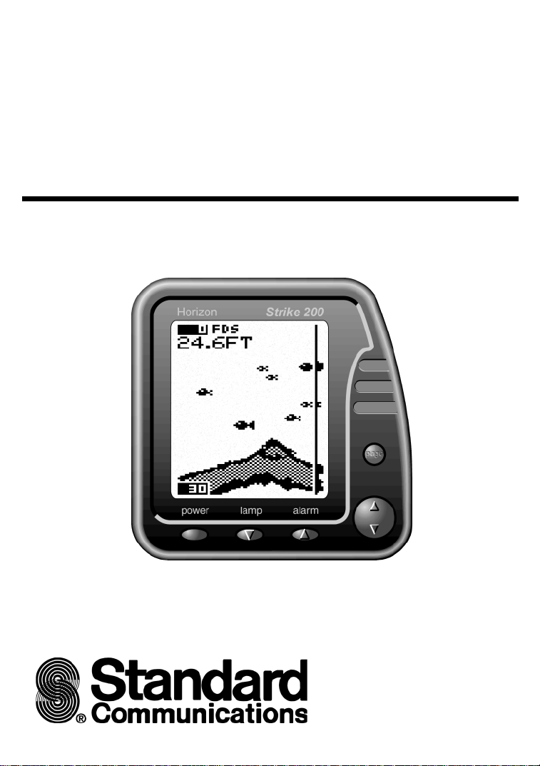
Strike 200
Thank you for purchasing a Horizon 200 SERIES fishfinder. The 200 SERIES is a powerful, yet easy
to use sonar fish and bottom depth detector. Please read this manual carefully before installing and
using your fishfinder. This manual deals with both the
Strike 200
and
220s
. The more you know and
understand about the capabilities of the unit, the better it will perform for you.
Specifications for 200 SERIES
• Dimensions
5.2" (132 mm) W (max) x 5.25" (133 mm) H x
1.8" (46 mm) D
• Depth Capability
600 feet, 180 metres
• Transducer Type
Aquatic transom-mount single beam. Thru
hull transducer options are also available.
• Operating Frequency
200 kHz
• Receiver Sensitivity
30 micro volts RMS
• Power Output
440 watts RMS (3500 watts peak-to-peak)
maintained within 10% down to 10.5 volts.
• Display Size
4¼" (100mm) Diagonal.
3¼" x 3" (82 mm x 76 mm)
• Display Type
STN temperature compensated
• Display Matrix
100 x 64 pixels
• Input Volta ge
10 to 18 volts DC @ 150 mA max. (lights on)
• Backlighting
Even illumination. Seven levels plus off.
• Operation Temperature
32°F to 104°F ambient (0°C to 40°C)
Additional Strike 220s Specifications
• Boat Speed
0.0–50.0 kts, mph, kph user selectable
• Water Temperature
32.0–99.0°F (0.0–40.0°C) user selectable
• Log
Records up to 9999.9 nm, km, stored in
memory, resetable.
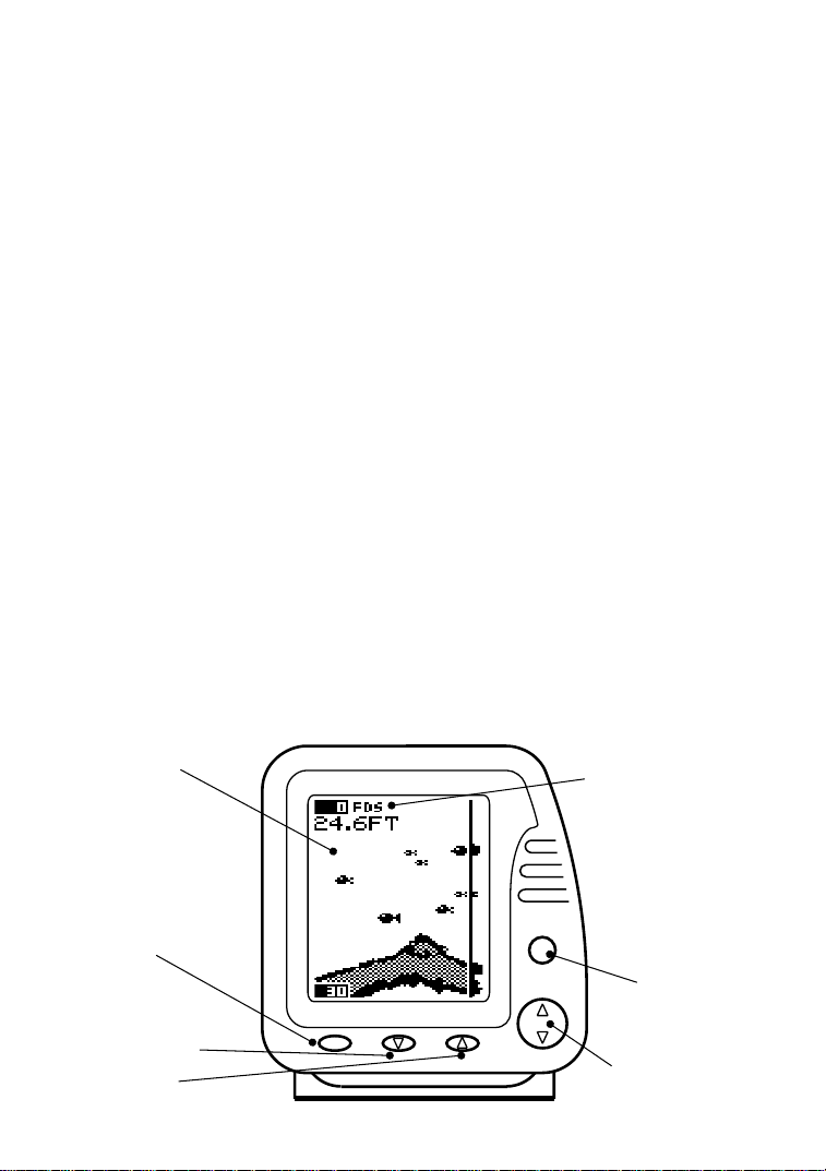
Display is backlit for
Night Operation
Power On/Off
Menu Exit
Backlighting On/Off
Change Value Down
Alarms On/Off
Change Value Up
Horizon Strike 200
power
lamp alarm
Active alarms indication
F=Fish, D=Deep, S=Shallow
page
Advance to Next Menu
MoveThrough Menu Items
Horizon Fishfinder User Manual4
Enter Menu Mode

Installation
Strike 200
Location
The
Strike 200
may be mounted and operated in many positions
thanks to its compact and robust bracket,
associated with a swivel support.
transducer and wiring before finalising the
location of the display head and bracket.
When installing the display head, select a position
and
220s
are water resistant and
Note
It may be advisable to install the
1.4" (35.0)
where it will be:
• at least 12" (300 mm) away from the
compass.
• at least 12" (300 mm) away from any radio
transmitter, such as the VHF.
• easy to read by the helmsman and crew
while under way.
• protected from physical damage during
rough sea passages.
• have easy access to the 12 volt power
source.
• convenient to route the transducer cables.
5.2" (132.0)
Horizon Strike 200
5.9" (149.0)
3.2" (81.5)
Horizon Fishfinder User Manual 5
5.25“ (133.0)
power
page
lamp alarm
Installation The Transducer
Read this section carefully before attempting the
transducer installation. Remember, the
transducer location is the most critical part
of the installation. If this is not done properly,
the transducer can’t perform at its designed
potential. Therefore the performance of the
fishfinder, especially at higher speeds, will not be
satisfactory.
Transom Mount Transducer
Location
The transducer can be installed on any outboard
or sterndrive powered boat. The transom mount
transducer has a safety “kic k up” mounting brac ket
to help minimise damage to the transducer should
it impact the bottom or floating debris in the water.
Select a position for the transducer that will:
• allow the transducer a smooth flow of water
over its surface at all times.
• ensure a mount as deep in the water as
possible.
• be clear of any interference from the trailer
when launching or retrieving the boat.
• be away from planing strakes or other
projections from the hull that may cause
aerated water to flow over the face of the
transducer.
• be away from the propeller
• be at least 150 mm ( 6" ) away from the keel
of the boat.
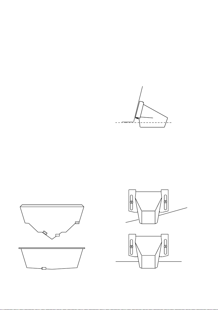
Mounting
Once the best location of the transducer is
determined, hold the transducer and bracket
against the transom. The bottom surface of the
transducer needs to sit parallel to the surface of
the water for the best signal return. The lower face
of the transducer should extend down below the
bottom of the hull so that it will be below the
surface of the water at high speeds. (See fig.
2.1)
fig. 2.1
Ideal water-line
Mark the transom through the bracket slots to
correctly place the two outer screws. Now drill
the two holes in the centre of the slots. This will
allow you to adjust the transducer position later
on if required. Use two of the three stainless
screws supplied to attach the bracket to the
transom. Ensure the lower f ace of the tr ansducer
is parallel with the ground (see fig. 3.1 and 3.2).
Tighten the two screws.
fig. 3.1
Poor Angle
Good Location
6
Poor Location
Good Location and Angle
fig. 3.2
DEEP-“VEE”
HULL
FLAT-BOTTOM
HULL
Horizon Fishfinder User Manual
 Loading...