

Page 1
SCU-31
GPS Antenna
External GPS Antenna
The SCU-31 is 66 channel GPS Antenna supplied with 49 feet of cable that plugs into your compatible
Standard Horizon VHF radio to enable AIS and DSC. The GPS antenna delivers accuracy better than
three meters by decoding the GPS correction signals from the SBAS (Satellite Based Augmentation
System). Please refer to the STANDARD HORIZON products catalog or web site for compatibility.
Owner’s Manual
The details of the installation and operation of the SCU-31 are included in the owner’s manual of
the compatible xed mount radio, or can be downloaded at www.standardhorizon.com.
Supplied Accessories
GPS Antenna Unit (49 feet cable) ......................................................................................................... 1
Antenna Base (Socket, Part number: RA6054200) .............................................................................. 1
Screws (M3X8 SUS, Part number: U20308020) .................................................................................. 3
2. Mount the antenna base to the antenna using the supplied three screws.
3. Screw the antenna base to the mounting bracket or extension pole.
4. Install the mounting bracket or extension pole in a location that has a clear view of the sky.
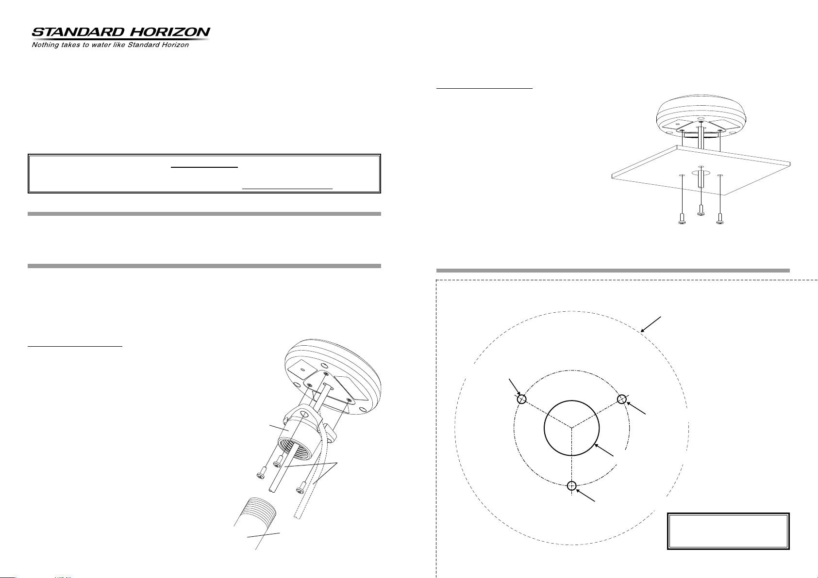
Flush Mounting the antenna
NOTE: Before drilling the mounting holes, it is
recommended to test the GPS antenna
satellite signal strength in the desired
location.
1. To ease installation use the supplied flush
mount template.
2. Apply the ush mounting template sticker.
3. Drill the 0.78” (20 mm) and 0.13” (3.2 mm)
holes, and remove the template.
4. Insert the cable into the 0.78” (20 mm) hole
and route to the transceiver.
5. Apply a small amount or RTV to the underside of the antenna.
6. Place the antenna and screw into place using the supplied screws.
Installing
The SCU-31 is designed to be mounted on a base, installed on an extension pole or ush mounted.
Choose a location for the antenna that has a clear view of the sky and is not located within 3 feet of
radar or other transmitting antenna. Ensure there are no major obstructions or xtures in the immediate proximity to the antenna. The antenna relies on direct "line of sight" satellite reception. If you are
unsure of the location, temporarily mount the antenna to verify correct operation. If mounted close to a
radar, turn on the radar and check the GPS signal strength using the GPS Status Page on the VHF.
Base Mounting the antenna
The thread used on the base of antenna (1 inch, 14 TPI)
is an industry standard used on a wide range of commer-
cially available mounting brackets or extension poles.
Due to the manufacturing process of the mounting brack-
ets, the antenna may not tighten all the way down onto all
the threads. This is of no concern however as the antenna must be tightened until the antenna stops rotating.
1. When passing the antenna cable through a mounting
bracket or extension pole, make sure to pass the cable through the antenna base.
NOTE: ・ When routing the antenna cable along the
outside of the extension pole, pass the cable
through the groove as shown by the dotted
lines in the gure on the right. (Please cut the
blank panel with a long-nose pliers.)
The antenna cable can be cut and spliced to ease
・
installation. Care must be taken when reconnecting the antenna cable to protect from water and
corrosion.
Antenna Base
Antenna Cable
Pole
Template
φ3.2 mm [0.13 inch]
cut here
cut here
TEMPLATE for the SCU-31
φ3.2 mm [0.13 inch]
φ20 mm [0.78 inch] or greater
φ3.2 mm [0.13 inch]
Use this template to mark the
location where the hole for
the ush mount is to be cut.
Page 2
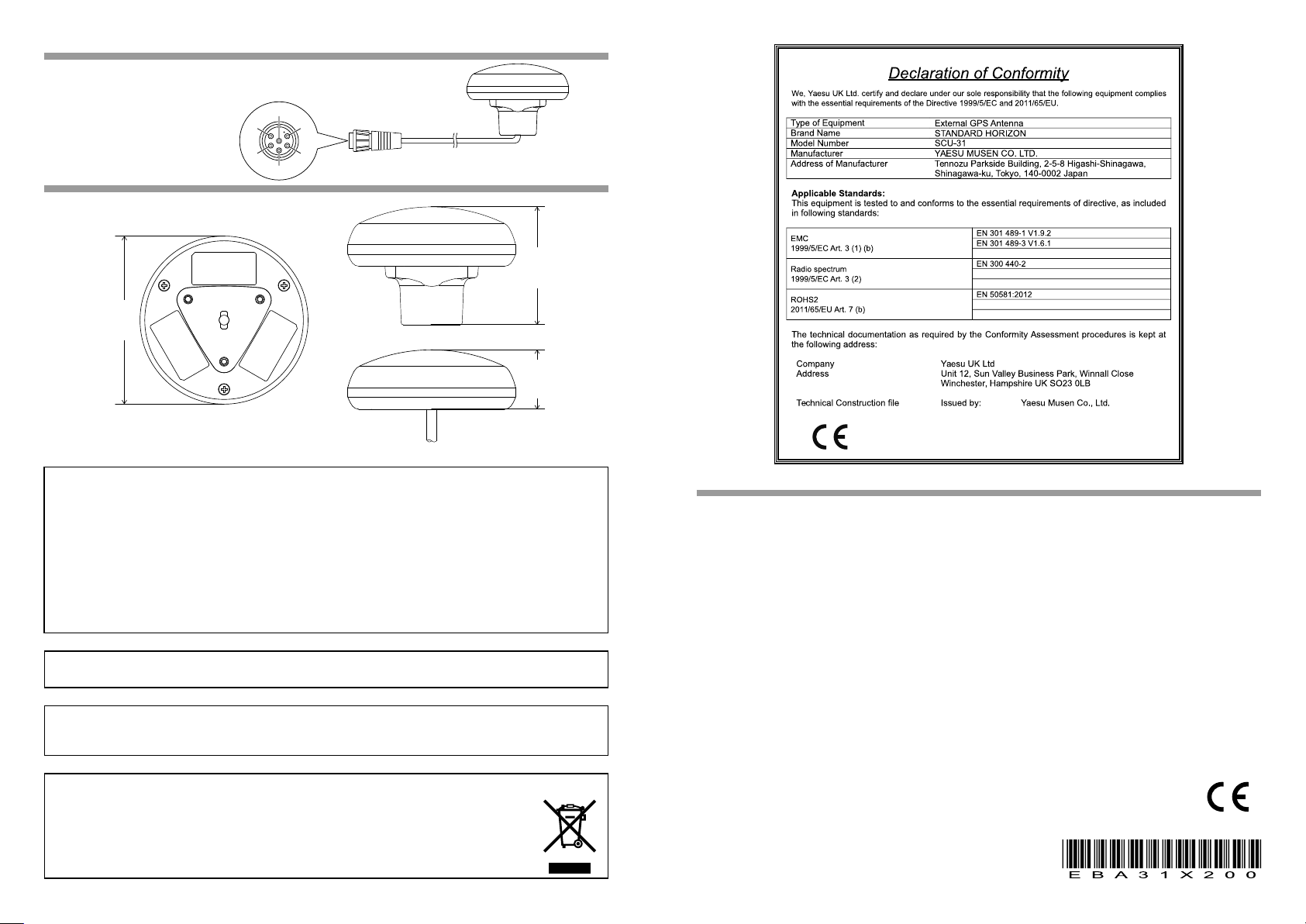
Pin Assignment
①
②
③
④
⑤
⑥
DC INPUT (+10 to 35 VDC)
①
GPS DATA OUTPUT (+)
②
GND
⑥
Dimensions
85 mm
30 mm 60 mm
This equipment has been tested and found to comply with the limits for a Class B digital device, pursuant to Part
15 of the FCC Rules. These limits are designed to provide reasonable protection against harmful interference in a
residential installation. This equipment generates, uses and can radiate radio frequency energy and, if not installed
and used in accordance with the instructions, may cause harmful interference to radio communications. However,
there is no guarantee that interference will not occur in a particular installation.
If this equipment does cause harmful interference to radio or television reception, which can be determined by
turning the equipment off and on, the user is encouraged to try to correct the interference by one or more of the
following measures:
• Reorient or relocate the receiving antenna.
• Increase the separation between the equipment and receiver.
• Connect the equipment into an outlet on a circuit different from that to which the receiver is connected.
• Consult the dealer or an experienced radio/TV technician for help.
Changes or modifications to this device not expressly approved by YAESU MUSEN could void the user’s
authorization to operate this device.
This device complies with part 15 of the FCC Rules. Operation is subject to the following two conditions; (1) this
device may not cause harmful interference, and (2) this device must accept any interference received, including
interference that may cause undesired operation.
Disposal of your Electronic and Electric Equipment
Products with the symbol (crossed-out wheeled bin) cannot be disposed as household waste.
Electronic and Electric Equipment should be recycled at a facility capable of handling these items
and their waste byproducts.
In EU countries, please contact your local equipment supplier representative or service center for
information about the waste collection system in your country.
Specications
Supply voltage ................................................................................. Normal: 13.8 VDC (Supplied from the transceiver)
Operating: 10 - 35 VDC
Power consumption .................................................................................................................................... 0.3 W (Max.)
Operating Temperature .......................................................................................... −4 °F to +140 °F (−20 °C to +60 °C)
Storage Temperature ............................................................................................−22 °F to +185 °F (−30 °C to +85 °C)
Receiving Frequency .................................................................................................................................. 1575.42 MHz
Receiving Code ....................................................................................................................................GPS: L1 C/A code
SBAS: WAAS, EGNOS, MSAS, GAGAN
Receiver Channels ........................................................................................................................................ 66 channels
Sensitivity .........................................................................................................................................Less than −147 dBm
Time to First Fix ....................................................................................................Hot start (Open Sky): 1 sec (approx.)
Cold start (Open Sky): 33 sec (typical)
Geodetic Datum .................................................................................................................................................. WGS84
Position Accuracy ..................................................................................................................................... 2.5 m (typical)
NMEA 0183 Output ................................................................................................. 4800 bps, 8 bits, no parity, 1stop bit
GGA, GLL, RMC, GSA and GSV
Dimensions ................................................................. 85 x 30 mm in height (ush mounted) or 60 mm on base mount
Weight (approx., without cable) ................................................................................................................... 3.2 oz (90 g)
Cable (approx.) ........................................................................................................................................... 49 feet (15 m)
YAESU MUSEN CO., LTD.
Tennozu Parkside Building
2-5-8 Higashi-Shinagawa, Shinagawa-ku, Tokyo 140-0002 Japan
YAESU USA
6125 Phyllis Drive, Cypress, CA 90630, U.S.A.
YAESU UK
Unit 12, Sun Valley Business Park, Winnall Close
Winchester, Hampshire, SO23 0LB, U.K.
QZSS
1611F-AS
 Loading...