

Page 1

QUANTUM GX6500E/GX6000E
25 Watt VHF/FM
Marine Transceiver
Owner’s Manual
Page 2

Page 2
GX6500E/GX6000E
TABLE OF CONTENTS
Quick Reference Guide ............................................................................... 4
1 GENERAL INFORMATION ..................................................................... 5
2 PACKING LIST .......................................................................................6
3 OPTIONAL ACCESSORIES ...................................................................6
4 GETTING STARTED...............................................................................7
4.1 PROHIBITED COMMUNICATIONS .............................................7
4.2 ABOUT VHF RADIO ....................................................................7
4.3 SELECTING AN ANTENNA .........................................................7
4.4 COAXIAL CABLE .........................................................................8
4.5 DISTRESS AND HAILING (CHANNEL 16) ..................................8
4.6 CALLING ANOTHER VESSEL (CHANNEL 16 OR 9)..................9
4.7 MAKING TELEPHONE CALLS ..................................................10
4.8 BRIDGE CHANNELS 13 AND 67 ..............................................10
4.9 AUTOMATED RADIO CHECK SERVICE .................................. 11
4.10 WHAT IS THE RANGE FOR AIS RECEIVERS? .......................12
5 INSTALLATION ....................................................................................13
5.1 SAFETY / WARNING INFORMATION .......................................13
5.2 LOCATION .................................................................................13
5.3 MOUNTING THE RADIO ...........................................................14
5.3.1 Supplied Mounting Bracket...........................................14
5.3.2 Optional MMB-84 Flush Mount Bracket........................15
5.4 ELECTRICAL CONNECTIONS .................................................16
5.5 REAR PANEL .............................................................................17
5.6 CONNECTION OF EXTERNAL DEVICES TO THE RADIO ......19
5.6.1 Connecting the SCU-31 External GPS Antenna to the
Radio ............................................................................19
5.6.2 Connecting the NMEA 0183/NMEA 0183-HS to the Radio
19
5.6.3 Accessory Cables and NMEA 0183 Cables .................20
5.6.4 NMEA 0813/NMEA 0183-HS to Chart Plotter ...............21
5.6.5 Connection to External GPS or Chart Plotter ...............23
5.6.6 Connection to External PA/HAIL Speaker ....................25
5.6.7 Rear Microphone Installation ........................................26
5.6.8 Optional SSM-70H (RAM4) Installation ........................26
5.7 INITIAL SETUP REQUIRED WHEN TURNING ON THE POWER
FOR THE FIRST TIME ..............................................................29
5.7.1 Setting the Welcome Screen and Region .....................29
5.7.2 Maritime Mobile Service Identity (MMSI) ......................29
5.8 CHECKING GPS SIGNAL (GPS STATUS DISPLAY) ................30
5.9 GPS CONFIGURATION.............................................................32
5.9.1 Changing the Gps Time ................................................32
5.9.2 Changing the Time Area ...............................................33
5.9.3 Changing the Time Format ...........................................33
5.9.4 Changing Cog to True or Magnetic...............................34
6 CONTROLS AND INDICATORS ..........................................................35
6.1 FRONT PANEL ..........................................................................35
6.2 MICROPHONE ..........................................................................37
7 BASIC OPERATION ............................................................................. 39
7.1 TURNING ON AND OFF THE TRANSCEIVER .........................39
7.2 RECEPTION ..............................................................................39
7.3 TRANSMISSION ........................................................................39
7.3.1 Transmit Power ............................................................40
7.4 TRANSMIT TIME-OUT TIMER (TOT) ........................................40
7.5 SIMPLEX/DUPLEX CHANNEL USE ..........................................40
7.6 INTERNATIONAL, USA AND CANADA MODE .........................41
7.7 MULTI WATCH (TO PRIORITY CHANNEL) ..............................42
7.7.1 Setting up the Multi Watch Operation ...........................42
7.7.2 Starting the Dual Watch ................................................43
7.8 SCANNING ................................................................................43
7.8.1 Selecting the Scan Type ...............................................43
7.8.2 Programming Scan Memory .........................................44
7.8.3 Memory Scanning (M-SCAN) .......................................45
7.8.4 Priority Scanning (P-SCAN) .........................................45
7.9 PRESET CHANNELS: INSTANT ACCESS ...............................46
7.9.1 Programming ................................................................46
7.9.2 Operation ......................................................................47
7.9.3 Deletion ........................................................................47
7.10 MOB OPERATION .....................................................................47
7.11 PA/FOG OPERATION ................................................................48
7.11.1 Operating the PA HAIL mode........................................49
7.11.2 Operating the FOG HORN mode .................................50
7.11.3 Fog Signal Timing Chart ...............................................51
7.11.4 Operating the HORN mode ..........................................52
7.12 INTERCOM OPERATION ..........................................................52
7.12.1 Communication.............................................................52
7.12.2 Calling...........................................................................53
7.13 VOICE SCRAMBLER ................................................................53
7.14 DEMO MODE ............................................................................54
7.15 OPERATION MENU ..................................................................55
8 GPS OPERATION.................................................................................57
8.1 DISPLAYING POSITION INFORMATION ..................................57
8.1.1 GPS Information Numerical Display .............................57
8.1.2 GPS Information Compass Display ..............................57
8.2 CHECKING GPS STATUS .........................................................58
8.3 GPS LOGGER OPERATION .....................................................59
9 DIGITAL SELECTIVE CALLING (DSC) ...............................................60
9.1 GENERAL ..................................................................................60
9.2 DSC DISTRESS ALEART ..........................................................61
9.2.1 Transmitting a DSC Distress Aleart ..............................61
9.2.2 Receiving a DSC Distress Aleart ..................................64
9.3 ALL SHIPS CALL .......................................................................66
9.3.1 Transmitting an All Ships Call .......................................66
9.3.2 Receiving an All Ships Call ...........................................67
9.4 INDIVIDUAL CALL .....................................................................68
9.4.1 Setting up the Individual / Position Call Directory .........68
9.4.2 Setting up the Individual Call Reply ..............................70
9.4.3 Enabling the Individual Call Acknowledgment ..............70
9.4.4 Transmitting an Individual Call .....................................71
9.4.5 Receiving an Individual Call .........................................73
9.4.6 Setting up the Individual Call Ringer ............................75
9.5 GROUP CALL ............................................................................77
9.5.1 Setting up a Group Call ................................................77
9.5.2 Transmitting a Group Call .............................................79
9.5.3 Receiving a Group Call.................................................82
9.5.4 Setting up the Group Call Ringer..................................83
9.6 POSITION REQUEST ...............................................................84
9.6.1 Setting up a Position Request Reply ...........................84
9.6.2 Transmitting a Position Request to Another Vessel ......85
9.6.3 Receiving a Position Request.......................................87
9.6.4 Manual Input of Position Information ............................88
9.6.5 Setting up a Position Request Ringer...........................89
9.7 POSITION REPORT ..................................................................90
9.7.1 Transmitting a DSC Position Report Call......................90
9.7.2 Receiving a DSC Position Report Call .........................92
9.7.3 Navigating to the Reported Position .............................92
9.7.4 Saving the Reported Position as a Waypoint ...............93
9.7.5 Setting up a Position Report Ringer .............................94
9.8 POLLING CALL..........................................................................95
9.8.1 Transmitting a Polling Call to a Vessel .........................95
9.8.2 Receiving a Polling Call ................................................97
9.9 AUTO POSITION POLLING ......................................................97
9.9.1 Setting up the Polling Operation ...................................97
9.9.2 Setting up the Polling Time Interval ..............................98
9.9.3 Selecting Vessels to be Automatically Polled ...............98
9.9.4 Enabling/Disabling Auto POS Polling ...........................99
9.10 DSC TEST ...............................................................................100
9.10.1 Programming MMSI into Individual Directory .............100
9.10.2 Transmitting a DSC Test to Another Vessel ................100
9.10.3 Receiving a DSC Test Call .........................................102
9.11 DSC LOG OPERATION ...........................................................102
9.11.1 Reviewing and Resending a Transmitted Logged Call 102
9.11.2 Reviewing a Logged DSC RX Distress Call ...............103
9.11.3 Reviewing Other Logged Calls ...................................104
9.11.4 Deleting Logged Calls from the DSC Log Directory ...105
9.12 DSC LOOP BACK OPERATION ..............................................106
10 NAVIGATION ......................................................................................107
Page 3

Page 3
GX6500E/GX6000E
TABLE OF CONTENTS
10.1 WAYPOINT OPERATION ........................................................107
10.1.1 Starting and Stopping Navigation ...............................107
10.1.2 Setting Up Waypoint Directory ...................................109
10.1.3 Selecting the Display Range ...................................... 113
10.1.4 Selecting the Arrival Range ........................................ 114
10.2 ROUTING OPERATION...........................................................115
10.2.1 Setting Up Routing Directory ...................................... 115
10.2.2 Starting and Stopping Route Navigation .................... 118
10.2.3 Changing the Destination ........................................... 119
10.2.4 Selecting Automatic or Manual Routing......................119
11 GM OPERATION ................................................................................120
11.1 SETTING UP GM OPERATION ...............................................120
11.1.1 Setting Up GM Group Directory..................................120
11.1.2 Setting Up the Polling Time Interval ...........................122
11.1.3 Enabling/Disabling Transmission during GM Operation ...
122
11.2 STARTING GM OPERATION ..................................................123
11.2.1 Changing the GM Group Being Monitored .................124
11.2.2 Transmitting a DSC Call to a Group Member .............124
11.2.3 Starting Navigation to a Group Member .....................125
12 AUTOMATIC IDENTERIFICATION SYSTEM (AIS) ...........................126
12.1 GENERAL ................................................................................126
12.2 AIS OPERATION .....................................................................127
12.2.1 Displaying the AIS Target Information Screen ............127
12.2.2 Changing the AIS Range ............................................129
12.2.3 Transmitting an Individual Call to an AIS Ship ............129
12.2.4 CPA/TCPA Alarm Functions .......................................130
12.2.5 Changing the Compass Display .................................131
12.3 AIS SETUP ..............................................................................131
12.3.1 Transponder (Only for GX6500) .................................131
12.3.2 Vessel Infomation (Only for GX6500) .........................131
12.3.3 CPA .............................................................................133
12.3.4 TCPA ..........................................................................134
12.3.5 CPA/TCPA Alarm ........................................................135
13 NMEA 2000 SETUP ............................................................................136
13.1 SELECT DIVICE ......................................................................136
13.2 DIVICE INSTANCE ..................................................................136
13.3 SYSTEM INSTANCE ...............................................................137
13.4 SUMMARY OF THE NMEA 2000 SETUP................................138
13.5 COMPATIBLE NMEA-2000 PGN LIST ....................................138
14 CONFIGURATION SETUP .................................................................140
14.1 DISPLAY MODE ......................................................................140
14.2 DIMMER ADJUSTMENT..........................................................141
14.3 DISPLAY CONTRAST .............................................................141
14.4 KEY BEEP ...............................................................................142
14.5 FOG ALERT TONE FREQUENCY...........................................142
14.6 LISTEN BACK ..........................................................................143
14.7 STATION NAME.......................................................................143
14.8 SOFT KEYS .............................................................................145
14.8.1 Key Assignment ..........................................................145
14.8.2 Key Timer ...................................................................146
14.9 RESET .....................................................................................147
14.10 SUMMARY OF THE CONFIGURATION SETUP .....................148
15 CHANNEL FUNCTION SETUP ..........................................................149
15.1 CHANNEL GROUP ..................................................................149
15.2 WEATHER ALERT ...................................................................149
15.3 SCAN MEMORY ......................................................................149
15.4 SCAN TYPE .............................................................................149
15.5 SCAN RESUME .......................................................................150
15.6 MULTI WATCH .........................................................................150
15.7 PRIORITY CHANNEL ..............................................................150
15.8 SUB CHANNEL........................................................................151
15.9 CHANNEL NAME.....................................................................151
15.10 NOISE CANCELLATION .........................................................152
15.11 AUDIO FILTER OPERATION...................................................153
15.12 RX RECORDER ......................................................................154
15.12.1 RX Recorder Function ON/OFF .................................154
15.12.2 Setting for Recording Delay Time ...............................154
15.12.3 Setting for End of Tone ...............................................155
15.12.4 Data Erase..................................................................156
15.13 SCRAMBLER SETUP ..............................................................157
15.14 SUMMARY OF THE CANNEL FUNCTION SETUP .................158
16 DSC SETUP ........................................................................................ 159
16.1 INDIVIDUAL DIRECTORY .......................................................159
16.2 INDIVIDUAL REPLY ................................................................159
16.3 INDIVIDUAL ACKNOWLEDGMENT ........................................159
16.4 INDIVIDUAL RINGER ..............................................................159
16.5 GROUP DIRECTORY ..............................................................159
16.6 POSITION REPLY ...................................................................160
16.7 AUTO POSITION POLLING ....................................................160
16.8 AUTO POSITION INTERVAL ...................................................160
16.9 AUTO CHANNEL CHANGE .....................................................160
16.10 NO ACTION TIMER .................................................................161
16.11 WAIT TIME FOR POSITION FIX .............................................162
16.12 DSC BEEP ...............................................................................162
16.13 SUMMARY OF THE DSC SETUP MENU................................163
17 GPS SETUP ........................................................................................ 164
17.1 ORDER OF PRIORITY ............................................................164
17.2 DISPLAY DIRECTION .............................................................165
17.3 LOCATION FORMAT ...............................................................165
17.4 TIME OFFSET .........................................................................166
17.5 TIME AREA ..............................................................................166
17.6 TIME FORMAT.........................................................................166
17.7 UNITS OF MEASURE .............................................................166
17.8 MAGNETIC VARIATION ..........................................................167
17.9 NMEA 0183 IN/OUT .................................................................167
17.9.1 Data Speed.................................................................167
17.9.2 Output Sentences .......................................................168
17.10 OPTION GPS UNIT .................................................................169
17.10.1 Unit Power .................................................................. 169
17.10.2 Position Data Output ..................................................170
17.10.3 Pinning........................................................................171
17.10.4 SBAS (Satellite Based Augmentation System)...........171
17.10.5 Logger Interval............................................................172
17.10.6 Log Erase ................................................................... 173
17.11 SUMMARY OF THE GPS SETUP ...........................................174
18 SSM-70H (RAM4) REMOTE MIC OPERATION ................................. 175
18.1 REMOTE MIC CONTROLS .....................................................175
18.2 RAM4 SOFT KEY ASSIGNMENT ............................................178
18.2.1 Key Assignment ..........................................................179
19 CONNECTING A USB DATA TERMINAL TO THE PC ......................180
20 MAINTENANCE .................................................................................. 181
20.1 REPLACEMENT PARTS .........................................................181
20.2 FACTORY SERVICE ...............................................................182
20.3 TROUBLESHOOTING CHART ................................................182
21 ATIS SETUP .......................................................................................184
21.1 ATIS CODE PROGRAMMING .................................................184
21.2 ATIS CH GROUP .....................................................................185
22 CHANNEL ASSIGNMENTS................................................................186
23 WARRANTY........................................................................................188
24 SPECIFICATIONS ..............................................................................190
24.1 GENERAL ................................................................................190
24.2 TRANSMITTER .......................................................................190
24.3 TRANSMITTER (for AIS) *GX6500 Only .................................191
24.4 RECEIVER (for Voice and DSC) ..............................................191
24.5 RECEIVER (for AIS) ................................................................191
24.6 GPS RECEIVER ......................................................................191
24.7 NMEA OUTPUT .......................................................................192
24.8 SCU-31 EXTERNAL GPS ANTENNA (*GX6000 Optional) ......192
Page 4
Page 4
GX6500E/GX6000E
Quick RefeRence Guide
The GX6500E/GX6000E is equipped with the E2O (Easy-To-Operate) menu
system. Basic operation may be accomplished by following the procedure below:
Press and hold the key to turn on or off the radio.
The MODE/STATUS indicator indicates the status of the transceiver. RED:
XXXXX. BLUE: XXXXX.
Rotate the SQL knob clockwise to squelch or counter clockwise to
un-squelch the radio.
Rotate the VOL knob to adjust the speaker audio volume.
Press the MENU key to access MENU.
Press the 16/S key on the radio or the microphone to select channel 16.
Press and hold the 16/S key on the radio or the microphone to select sub
channel. Press again to revert to the last selected channel.
Activates a DSC distress call. Lift the red cover, press the DISTRESS once,
then press and hold until the radio alarms.
These three programmable soft keys can be customized through the setup
menu mode. By pressing one of these keys briey, display the key functions
at the bottom of the display.
Press the ▲/▼ key (or press the microphone’s ▲/▼ keys) to select the
operating channel. While the MENU screen is displayed, press the key to
slide the on-screen menu upward/downward.
Press the ►/◄ key to switch the function menu. While the MENU screen is
displayed, press the key to slide the on-screen menu to the right/left side.
Press the CLEAR key to cancel a function or menu selection.
While the normal screen is displayed, rotate the DIAL/ENT knob to select
your desired channel. While the MENU screen is displayed, rotate the knob
to select your desired menu item.
To transmit: place your mouth about 1/2 inch away from Mic hole and speak
in a normal voice level while pressing the PTT switch.
Press the H/L key to toggle the transmit power between High (25W) and
Low (1W).
Page 5

Page 5
GX6500E/GX6000E
1 GENERAL INFORMATION
The STANDARD HORIZON GX6500E/GX6000E Marine VHF/FM Marine
transceiver is designed to be used in USA, International, and Canadian Marine
bands. The GX6500E/GX6000E can be operated from 11 to 16 VDC and has a
switchable RF output power of 1 watt or 25 watts.
The GX6500E/GX6000E integrates a dual channel AIS (Automatic Identication System) receiver to display AIS vessel information (MMSI, Call Sign, Ship
Name, BRG, DST, SOG and COG) directly on the VHF radio, so you will know
what is out there in any conditions. The GX6500E/GX6000E built-in antenna
jack and receiver enable you to receive AIS signals while receiving a voice channel signals. The GX6500E/GX6000E is also capable of entering and saving up
to 250 waypoints, which may be selected and navigated to by using a unique
navigation compass display. The GX6500E/GX6000E allows you to contact
an AIS ship directly using DSC, show your vessels position in relation to AIS
targets and alert you when an AIS ship may be approaching too close to your
location via the Closest Point of Approach (CPA) Alarm. To receive AIS targets
from ships with AIS class A or B transponders, simply connect the normal VHF
antenna (only one antenna needed!).
The GX6500E/GX6000E is capable of DSC (Digital Selective Calling) ITU-R
M.493 Class D operation. Class D operation allows continuous receiving of
Digital Selective Calling functions on channel 70 even if the radio is receiving a
call. The GX6500E/GX6000E operates on all currently-allocated marine channels which are switchable for use with USA, International, or Canadian regulations. Emergency channel 16 can be immediately selected from any channel
by pressing the red 16/S key. NOAA weather channel can also be accessed
immediately by pressing the [WX] soft key.
Other features of the GX6500E/GX6000E includes: Noise canceling function
for transmit and receive audio, NMEA 2000 compatibility, high expandability,
two-minute recording function for listening to important conversations later,
speaker microphone, 30W PA/Fog, optional RAM4 second station remotecontrol microphone with AIS display, intercom between radio and optional
RAM4, scanning, priority scanning, submersible speaker microphone, high
and low voltage warning, and GPS repeatability.
Page 6

Page 6
GX6500E/GX6000E
2 PACKING LIST
When the package containing the transceiver is rst opened, please check it
for the following contents:
GX6500E/GX6000E Transceiver
Hand Microphone
Power Cord
Mounting Bracket and Hardware
Owner’s Manual
DSC Warning Sticker
Flush Mount Template
SCU-31 External GPS Antenna (GX6500 only)
T9101606 USB Cable (Type USB “A” plug to Type USB micro “B” plug)
3 OPTIONAL ACCESSORIES
MMB-84 ..........................................................................Flush-Mount Bracket
SSM-70H ........................................Remote-Access Microphone (RAM4 Mic)
SCU-31 .................................................. External GPS Antenna (for GX6000)
CT-100 .......... 23 Feet Microphone Extension Kit for connection to rear panel
MLS-300 ..................................................................... External Loud Speaker
220SW ............................................................5” Round 30 Watt Hail/PA Horn
240SW ........................................... 5” × 8” Rectangular 40 Watt Hail/PA Horn
SCU-31 .....................................External GPS Antenna with 49 Feet of Cable
Page 7

Page 7
GX6500E/GX6000E
4 GETTING STARTED
4.1 PROHIBITED COMMUNICATIONS
The FCC prohibits the following communications:
• False distress or emergency messages:
• Messages to “any boat” except in emergencies and radio tests;
• Messages to or from a vessel on land;
• Transmission while on land;
• Obscene, indecent, or profane language (potential ne of $10,000).
4.2 ABOUT VHF RADIO
The radio frequencies used in the VHF marine band lie between 156 and 158
MHz with some shore stations available between 161 and 163 MHz. The marine
VHF band provides communications over distances that are essentially “line of
sight” (VHF signals do not travel well through objects such as buildings, hills
or trees). Actual transmission range depends much more on antenna type,
gain and height than on the power output of the transmitter. On a xed mount
25W radio transmission expected distances can be greater than 15 miles, for
a portable 5W radio transmission the expected distance can be greater than
5 miles in “line of sight”.
4.3 SELECTING AN ANTENNA
Marine antennas are made to radiate signals equally in all horizontal directions,
but not straight up. The objective of a marine antenna is to enhance the signal
toward the horizon. The degree to which this is accomplished is called the
antenna’s gain. It is measured in decibels (dB) and is one of the major factors
in choosing an antenna. In terms of effective radiated power (ERP), antennas
are rated on the basis of how much gain they have over a theoretical antenna
with zero gain. A 3-foot, 3dB gain antenna represents twice as much gain over
the imaginary antenna.
Typically a 3-foot 3dB gain stainless steel whip is used on a sailboat mast. The
longer 8-foot 6dB berglass whip is primarily used on power boats that require
the additional gain.
3dB
6dB
9dB
Page 8
Page 8
GX6500E/GX6000E
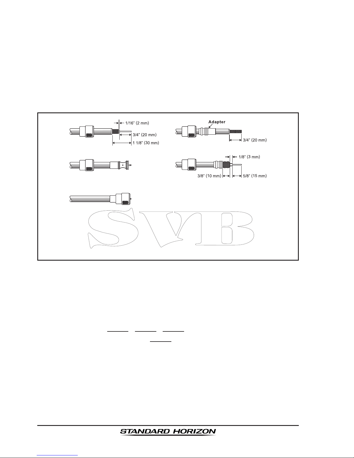
4.4 COAXIAL CABLE
VHF antennas are connected to the transceiver by means of a coaxial cable
– a shielded transmission line. Coaxial cable is specied by it’s diameter and
construction.
For runs less than 20 feet, RG-58/U, about 1/4 inch in diameter is a good choice.
For runs over 20 feet but less than 50 feet, the larger RG-8X or RG-213/U should
be used for cable runs over 50 feet RG-8X should be used. For installation of
the connector onto the coaxial cable refer to the gure below.
To get your coax cable through a tting and into your boat’s interior,
you may have to cut off the end plug and reattach it later. You can do
this if you follow the directions that come with the connector. Be sure
to make good soldered connections.
4.5 DISTRESS AND HAILING (CHANNEL 16)
Channel 16 is known as the Hail and Distress Channel. An emergency may be
dened as a threat to life or property. In such instances, be sure the transceiver
is on and set to CHANNEL 16. Then use the following procedure:
1. Press the microphone push-to-talk switch and say “Mayday, Mayday,
Mayday. This is , , ” (your vessel’s name).
2. Then repeat once: “Mayday, ” (your vessel’s name).
3. Now report your position in latitude/longitude, or by giving a true or magnetic
bearing (state which) to a well-known landmark such as a navigation aid
or geographic feature such as an island or harbor entry.
4. Explain the nature of your distress (sinking, collision, aground, re, heart
attack, life-threatening injury, etc.).
5. State the kind of assistance your desire (pumps, medical aid, etc.).
6. Report the number of persons aboard and condition of any injured.
7. Estimate the present seaworthiness and condition of your vessel.
Page 9

Page 9
GX6500E/GX6000E
8. Give your vessel’s description: length, design (power or sail), color and other
distinguishing marks. The total transmission should not exceed 1 minute.
9. End the message by saying “OVER”. Release the microphone switch and
listen.
10. If there is no answer, repeat the above procedure. If there is still no response,
try another channel.
NOTE
The GX6500E/GX6000E has the DSC Distress calling, that can transmit
a distress call digitally to all ships with compatible DSC radios. Refer
to section “10 DIGITAL SELECTIVE CALLING (DSC)”.
4.6 CALLING ANOTHER VESSEL (CHANNEL 16 OR 9)
Channel 16 may be used for initial contact (hailing) with another vessel.
However, its most important use is for emergency messages. This channel
must be monitored at all times except when actually using another channel.
It is monitored by the U.S. and Canadian Coast Guards and by other vessels.
Use of channel 16 for hailing must be limited to initial contact only. Calling should not exceed 30 seconds, but may be repeated 3 times at 2-minute
intervals. In areas of heavy radio trafc, congestion on channel 16 resulting
from its use as a hailing channel can be reduced signicantly in U.S. waters
by using channel 9 as the initial contact (hailing) channel for non-emergency
communications. Here, also, calling time should not exceed 30 seconds but
may be repeated 3 times at 2-minute intervals.
Prior to making contact with another vessel, refer to the channel charts in this
manual, and select an appropriate channel for communications after initial
contact. For example, Channels 68 and 69 of the U.S. VHF Charts are some
of the channels available to non-commercial (recreational) boaters. Monitor
your desired channel in advance to make sure you will not be interrupting
other trafc, and then go back to either channel 16 or 9 for your initial contact.
When the hailing channel (16 or 9) is clear, press the PTT switch on the mic and
state the name of the other vessel you wish to call and then “this is” followed by
the name of your vessel and your Station License (Call Sign) then release the
PTT switch on the mic. When the other vessel returns your call, immediately
request another channel by pressing the PTT switch on the mic and saying “go
to,” the number of the other channel, say “over” and release the PTT switch on
the mic. Then switch to the new channel. When the new channel is not busy,
call the other vessel.
Page 10

Page 10
GX6500E/GX6000E
After a transmission, say “over,” and release the microphone’s push-to-talk
(PTT) switch. When all communication with the other vessel is completed, end
the last transmission by stating your Call Sign and the word “out.” Note that
it is not necessary to state your Call Sign with each transmission, only at the
beginning and end of the contact.
Remember to return to Channel 16 when not using another channel. Some
radios automatically monitor Channel 16 even when set to other channels or
when scanning.
4.7 MAKING TELEPHONE CALLS
To make a radiotelephone call, use a channel designated for this purpose.
The fastest way to learn which channels are used for radiotelephone trafc
is to ask at a local marina. Channels available for such trafc are designated
Public Correspondence channels on the channel charts in this manual. Some
examples for USA use are Channels 24, 25, 26, 27, 28, 84, 85, 86, and 87. Call
the marine operator and identify yourself by your vessel’s name. The marine
operator will then ask you how you will pay for the call (telephone credit card,
collect, etc.) and then link your radio transmission to the telephone lines.
The marine telephone company managing the VHF channel you are using may
charge a link-up fee in addition to the cost of the call.
4.8 BRIDGE CHANNELS 13 AND 67
Channel 13 is used at docks, bridges and by vessels maneuvering in port.
Messages on this channel must concern navigation only, such as meeting and
passing in restricted waters.
Channel 67 is used for navigational trafc between vessels.
By regulation, power is normally limited to 1 Watt on these channels. Your radio
is programmed to automatically reduce power to this limit on these channels.
However, in certain situations it may be necessary to temporarily use a higher
power. See Page 40 for means to temporarily override the low-power limit
on these two channels.
Page 11

Page 11
GX6500E/GX6000E
4.9 AUTOMATED RADIO CHECK SERVICE
In areas across the country, Sea Tow offers boaters a way to conduct radio
checks. To use Sea Tow’s free Automated Radio Check service, simply tune
your VHF radio to the appropriate channel for your location and conduct a
radio check as you typically would. Upon releasing your radio’s microphone,
the system will play an automated message and relay your transmission back
to you, thereby letting you know how your signal will sound to other boaters.
The Automated Radio Check Service is currently available in the areas listed
below.
West Coast Sea Tow Newport/LA - Ch. 27
Sea Tow San Diego - Ch. 27
Northeast Sea Tow Portland-Midcoast (Maine) - Ch. 27
Sea Tow Boston - Ch. 27
Sea Tow South Shore (Mass.) - Ch. 28
Sea Tow Rhode Island - Ch. 24
Sea Tow Eastern Long Island - Ch. 27
Sea Tow Huntington (N.Y.) - Ch. 27
Sea Tow Manasquan (N.J.) - Ch. 28
Mid-Atlantic Sea Tow Northern Chesapeake (Md.) - Ch. 28
Sea Tow Central Chesapeake (Md.) - Ch. 27
Sea Tow Hampton Roads (Va.) - Ch. 28
North Carolina Sea Tow Wrightsville Beach - Ch. 28
Sea Tow Ocean Isle Beach - Ch. 28
Florida Sea Tow Sebastian - Ch. 28
Sea Tow Fort Lauderdale - Ch. 27
Sea Tow Charlotte Harbor - Ch. 24
Sea Tow Tampa Bay - Ch. 27
Sea Tow Horseshoe Beach - Ch. 27
Sea Tow Carrabelle/St. Marks - Ch. 27
Sea Tow Pensacola/Orange Beach (Ala.) - Ch. 27
Page 12

Page 12
GX6500E/GX6000E
4.10 WHAT IS THE RANGE FOR AIS RECEIVERS?
Since AIS uses similar frequencies as a marine VHF radio, it has similar radio
reception capabilities - which are basically line of sight. This means that the
higher the VHF antenna is mounted, the greater the reception area will be.
Reception from Class A vessels that are 20 or even 30 miles away on open
water is not uncommon as their antennas are mounted high off the water. Class
B transponders use lower power for transmissions; therefore you can expect
Class B vessels to be acquired when they are 5 to 10 miles away.
NOTE
The GX6500E/GX6000E does not require a special marine VHF
antenna to receive AIS transmissions. The GX6000 does not transmit
AIS signals, it is NOT recommended to use an antenna dedicated for
AIS operation.
For additional information on AIS visit the USCG website:
<http://www.navcen.uscg.gov/marcomms/ais.htm>
Page 13

Page 13
GX6500E/GX6000E
5 INSTALLATION
5.1 SAFETY / WARNING INFORMATION
This radio is restricted to occupational use, work related operations only where
the radio operator must have the knowledge to control the exposure conditions of
its passengers and bystanders by maintaining the minimum separation distance
of 3 feet (1 m). Failure to observe these restrictions will result in exceeding the
FCC RF exposure limits.
Antenna Installation:
The antenna must be located at least 3 feet (1 m) away from passengers in
order to comply with the FCC RF exposure requirements.
5.2 LOCATION
The radio can be mounted at any angle. Choose a mounting location that:
• is follow the compass safe distances shown in the table below to prevent
interference to a magnetic compass
Transceiver Unit 1.0 m
Handset 0.5 m
• provides accessibility to the front panel controls
• allows connection to a power source and an antenna
• has nearby space for installation of a microphone hanger
• is at least 3 feet (1 m) away from the radio’s antenna
• the signal from the GPS satellite can receive sufciently
Note: To insure the radio does not affect the compass or radios performance
is not affected by the antenna location, temporarily connect the radio in the
desired location and:
a. Examine the compass to see if the radio causes any deviation
b. Connect the antenna and key the radio. Check to ensure the radio is
operating correctly by requesting a radio check.
Page 14
Page 14
GX6500E/GX6000E
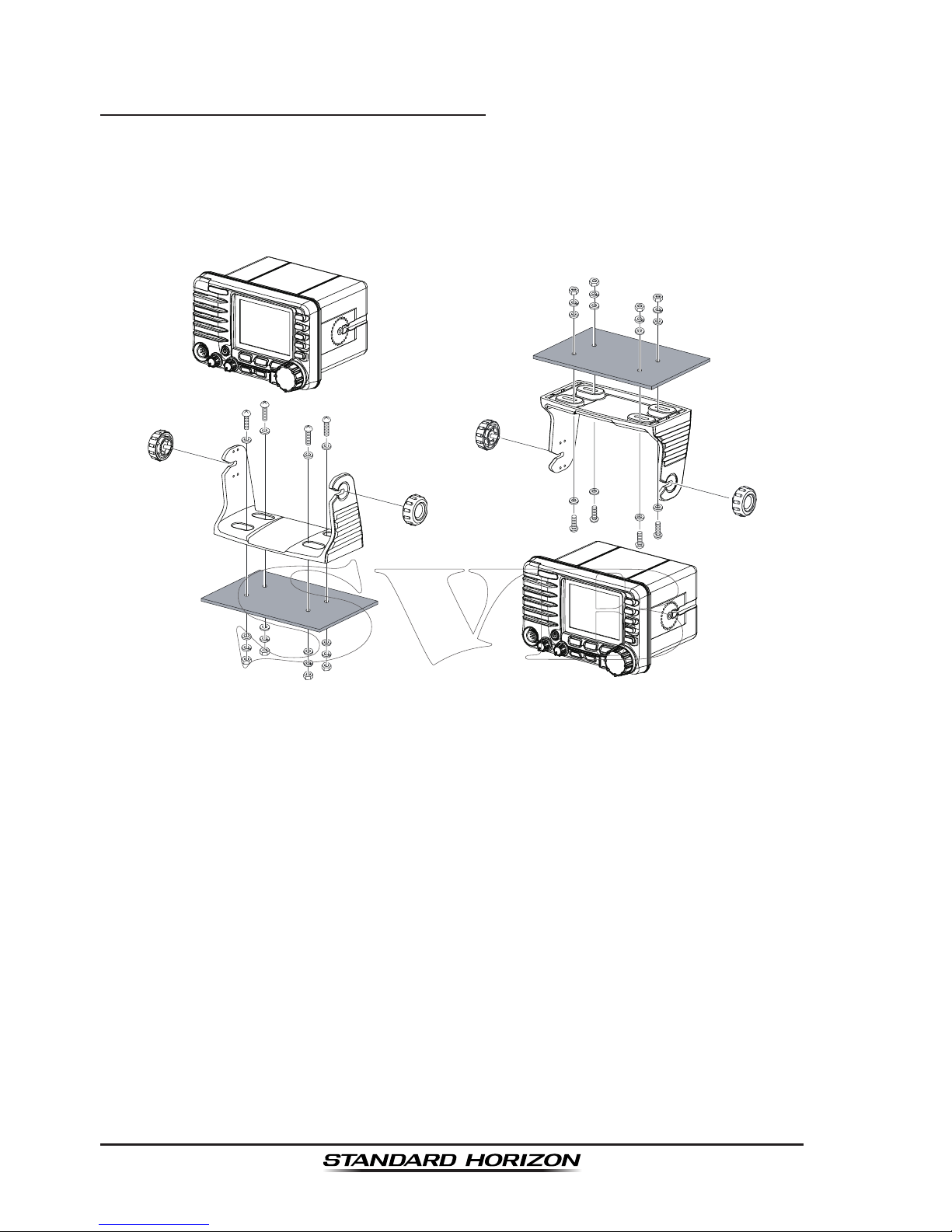
5.3 MOUNTING THE RADIO
5.3.1 Supplied Mounting Bracket
The supplied mounting bracket allows overhead or desktop mounting.
Use a 13/64” (5.2 mm) bit to drill the holes to a surface which is more 0.4” (10
mm) thick and can support more than 3.3 lbs (1.5 kg) and secure the bracket
with the supplied screws, spring washers, at washers, and nuts.
Desktop Mounting overheaD Mounting
Page 15
Page 15
GX6500E/GX6000E
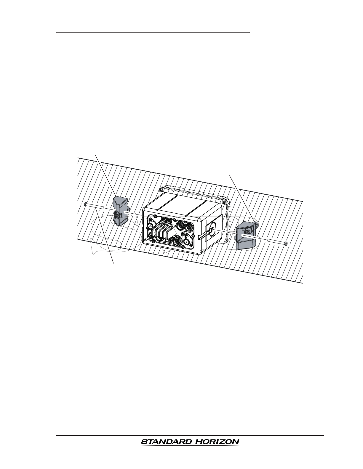
5.3.2 Optional MMB-84 Flush Mount Bracket
1. Use the supplied template to mark the location where the rectangular hole
is to be cut. Conrm the space behind the dash or panel is deep enough
to accommodate the transceiver (at least 6.7” (17 cm) deep).
There should be at least 1/2” (1.3 cm) between the transceiver’s heatsink
and any wiring, cables or structures.
2. Cut out the rectangular hole and insert the transceiver.
3. Fasten the brackets to the sides of the transceiver with the lock washer
screw combination; so that the mounting screw base faces the mounting
surface (see illustration below).
4. Turn the adjusting screw to adjust the tension so that the transceiver is tight
against the mounting surface.
Bracket
Lock-washer screw combination
Adjusting Screw
Page 16

Page 16
GX6500E/GX6000E
5.4 ELECTRICAL CONNECTIONS
CAUTION
Reverse polarity battery connections will damage the radio!
Connect the power cord and antenna to the radio. Antenna and Power Supply
connections are as follows:
1. Mount the antenna at least 3 feet (1 m) away from the radio. At the rear of
the radio, connect the antenna cable. The antenna cable must have a PL259
connector attached. RG-8/U coaxial cable must be used if the antenna is 25
feet (7.6 m) or more from the radio. RG58 cable can be used for distances
less than 25 feet (7.6 m).
2. Connect the red power wire to a 13.8 VDC ±20% power source. Connect
the black power wire to a negative ground.
3. If an optional remote extension speaker is to be used, refer to section 6.5
for connections.
4. It is advisable to have a Certied Marine Technician check the power output
and the standing wave ratio of the antenna after installation.
GPS Navigation Receiver
Optional Speaker
Optional Speaker
Fuse
Red
Power Source
Black
Voice
Antenna
Water proof
Deck Outlet
Optional SSM-70H
Remote MIC
Optional HAIL/PA Horn
Accessory Cables
AIS
Antenna
Optional SCU-31
GPS Antenna
Fuse Replacement
To take out the fuse from the fuse holder, hold
both ends of the fuse holder and pull the fuse
holder apart without bending the fuse holder.
When you replace the fuse, please conrm that
the fuse is tightly xed on the metal contact
located inside the fuse holder. If the metal
contact holding the fuse is loose, the fuse holder
may heat up.
Page 17
Page 17
GX6500E/GX6000E
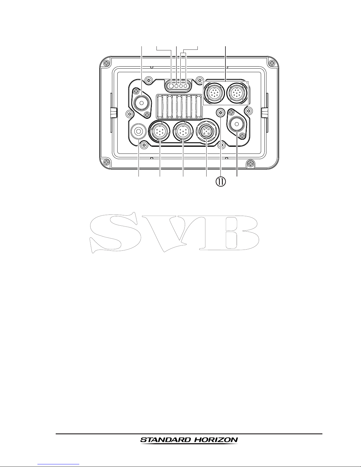
5.5 REAR PANEL
VHF ANT jack (VHF antenna jack)
Connects an antenna to the transceiver. Use a marine VHF antenna with
an impedance of 50 ohms.
Note: This ANT jack is used to receive marine receiver.
AIS ANT jack (AIS antenna jack)
Connects an antenna to the transceiver. Use a marine VHF antenna with
an impedance of 50 ohms.
Note: On the GX6000 the antenna connection is used to AIS receiver.
PA Speaker Connection Cable (Orange, Yellow, Green & Blue)
Connects the GX6500E/GX6000E to PA speakers. See section “3 OPTION-
AL ACCESSORIES” for a list of optional STANDARD HORIZON Speakers.
Green: PA FWD Speaker (+)
Blue: PA FWD Speaker (−)
Orange: PA AFT Speaker (+)
Yellow: PA AFT Speaker (−)
EXTERNAL Speaker Connection Cable (Red & White)
Connects the GX6500E/GX6000E to an optional external speaker. Refer
to section “3 OPTIONAL ACCESSORIES” for a list of optional STANDARD
HORIZON Speakers.
Red: External Speaker (+)
White: External Speaker (−)
DC Input Cable
Page 18

Page 18
GX6500E/GX6000E
Connects the radio to a DC power supply capable of delivering 11 to 16VDC.
RAM4 Connector (SSM-70H Remote Station Microphone Connector)
Connects the GX6500E/GX6000E to the SSM-70H (RAM4) Remote Station
Microphone. Refer to section “19 SSM-70H (RAM4) REMOTE MIC OPERA-
TION” for details.
NMEA 0183 In/Out & NMEA 0183-HS OUT Connection Cable (Blue, Green,
Gray, Brown, Yellow & White)
Connects the GX6500E/GX6000E to a GPS chart plotter. Refer to section
“6.6 CONNECTION OF EXTERNAL DEVICES TO THE RADIO”.
Rear MIC Connector
Connects the supplied hand microphone if desired. This connector provides
the same function as that on the front panel and allows remote use of the
microphone by using the optional MEK-4 (microphone extension kit). Two
microphones on the front and rear panels are available at the same time.
GPS ANT Connector
Connects the SCU-31 external GPS antenna.
NMEA 2000 Connector
Connects to the NMEA 2000 network.
GND Terminal (Ground Terminal)
Connects the GX6500E/GX6000E to a good ground, for safe and optimum
performance.
Use the screw supplied with the GX6500E/GX6000E only.
Page 19

Page 19
GX6500E/GX6000E
5.6 CONNECTION OF EXTERNAL DEVICES TO THE RADIO
5.6.1 Connecting the SCU-31 External GPS Antenna to the Radio
Connect the SCU-31 cable to the GPS
ANT (six pin) connector on the rear
panel, then tighten the cable nut (see
illustration at the right).
5.6.2 Connecting the NMEA 0183/NMEA 0183-HS to the Radio
External GPS Connections (NMEA 0183 4800 baud or NMEA 0183-HS
38400 baud)
The GX6500E/GX6000E can select the NMEA baud rate between “4800 bps”
and “38400 bps”. Refer to section “18.9 NMEA 0183 IN/OUT” for selection.
NMEA Input (GPS Information)
• GX6500E/GX6000E can read NMEA 0183 version 2.0 or higher, and NMEA
0183-HS version 1.01 or higher.
• The NMEA 0183 input sentences are GLL, GGA, RMC, GNS, GSA, and
GSV (RMC sentence is recommended).
• If 4800 baud (default) is selected:
a. If there is a selection for “PARITY” select “NONE”.
b. The Blue and Green wires of input are at 4800 baud.
• If 38400 baud is selected:
The Blue and Green wires of input are at 38400 baud.
NMEA Output (DSC and GPS information)
• The NMEA 0183 output sentences are DSC and DSE.
• If 4800 baud (default) is selected:
a. The Gray and Brown wires output DSC and DSE sentences.
b. The Yellow and White wires of output AIS VDM sentence at 38400
baud.
• If 38400 baud is selected:
a. The Gray and Brown wires of output are at 38400 baud and includes
both DSC (DSC, DSE) and AIS (VDM) sentences.
b. The Yellow and White wires always output AIS sentences at 38400
baud.
• GSA, GSV, GLL, GGA, and RMC sentences can be output in the GX6500E/
GX6000E by setting through the GPS setup menu (refer to section “18.9
NMEA 0183 IN/OUT”).
For further information on interfacing/setting up your GPS, please contact the
Page 20

Page 20
GX6500E/GX6000E
manufacturer of the GPS receiver externally connected.
If you have further inquires, please feel free to contact Product Support at:
Phone: (800) 767-2450
Email: marinetech@yaesu.com
5.6.3 Accessory Cables and NMEA 0183 Cables
The image and table below show the wires of the GX6500E/GX6000E and the
connections to optional devices such as a external GPS antenna, GPS chart
plotter and an AIS receiver or transponder.
CAUTION
Care must be taken not to touch any of the NMEA wires to positive 12
VDC or the radio may be damaged.
When connecting the GPS navigation receiver, strip off about 1 inch (2.5 cm)
of the specied wire’s insulation, then splice the ends together.
The GX6500E/GX6000E uses NMEA 0183 protocol to share coordinates, DSC
and AIS information to and from a GPS chart plotter. The GX6500E/GX6000E
transfers AIS information to a GPS chart plotter at 38400 baud (sometimes
called HS). GPS and DSC information is transferred between a GPS chart
plotter with multiple ports (minimum 2) at 4800 baud (default setting).
To connect to a GPS chart plotter which has one NMEA port, the GX6500E/
GX6000E may be setup to receive GPS coordinates, send DSC and AIS signals
at 38400 baud. Refer to section “18.9 NMEA 0183 IN/OUT” for details.
Page 21
Page 21
GX6500E/GX6000E
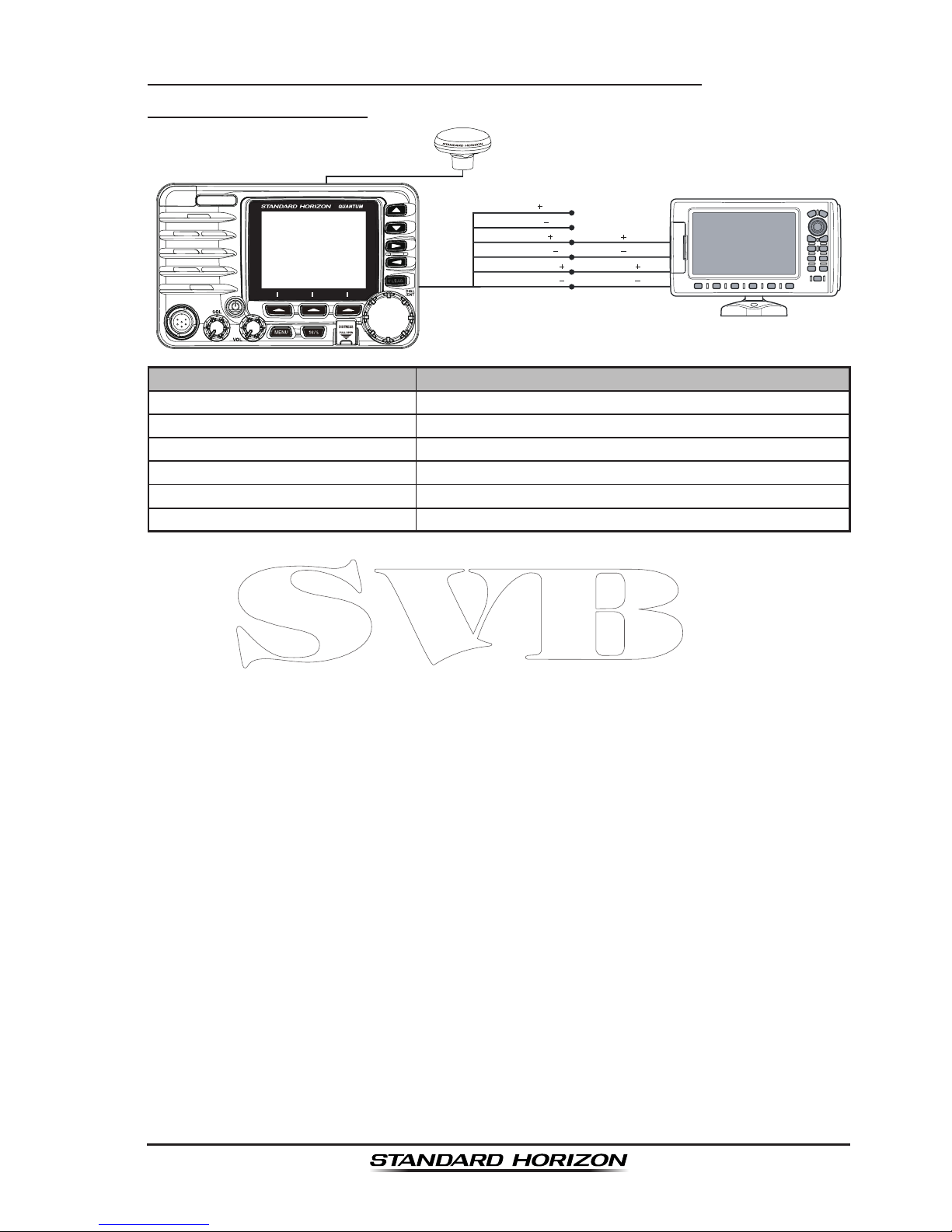
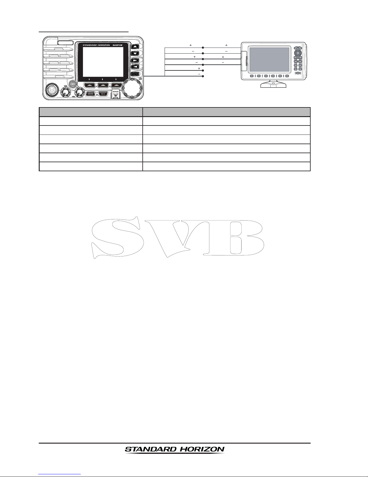
5.6.4 NMEA 0813/NMEA 0183-HS to Chart Plotter
4800 Baud Connections
GPS Chart Plotter
Plotter Connection
Radio Wires
Gray: NMEA OUT
( )
Brown: NMEA OUT
( )
Yellow: NMEA-HS OUT
( )
White: NMEA-HS OUT
( )
Blue: NMEA IN
( )
No Connection
No Connection
NMEA IN
( )
NMEA IN-HS
( )
NMEA IN
( )
NMEA IN-HS
( )
Green: NMEA IN
( )
GPS Antenna
Wire Color/Description Connection Examples
BLUE - NMEA GPS Input (+) No connection
GREEN - NMEA GPS Input (−) No connection
GRAY - NMEA DSC Output (+) NMEA (+) input of GPS*
1
BROWN - NMEA DSC Output (−) NMEA (−) input of GPS*
1
YELLOW - AIS Data Output (+) NMEA-HS (+) input of AIS receiver*
2
WHITE - AIS Data Output (−) NMEA-HS (−) input of AIS receiver*
2
*1: 4800 baud
*2: 38400 baud
Note: Some GPS chart plotters have a single wire for NMEA signal ground. In such a case connect
the NMEA input (−) to the GPS chart plotter’s single NMEA signal ground wire, and leave the NMEA
output (−) open. In case the assignment of power supply and ground of a GPS chart plotter to be
used is different from that of the radio, connect the signal ground wire of the GPS chart plotter to
the ground terminal (GND) on the rear panel of the radio.
Page 22
Page 22
GX6500E/GX6000E
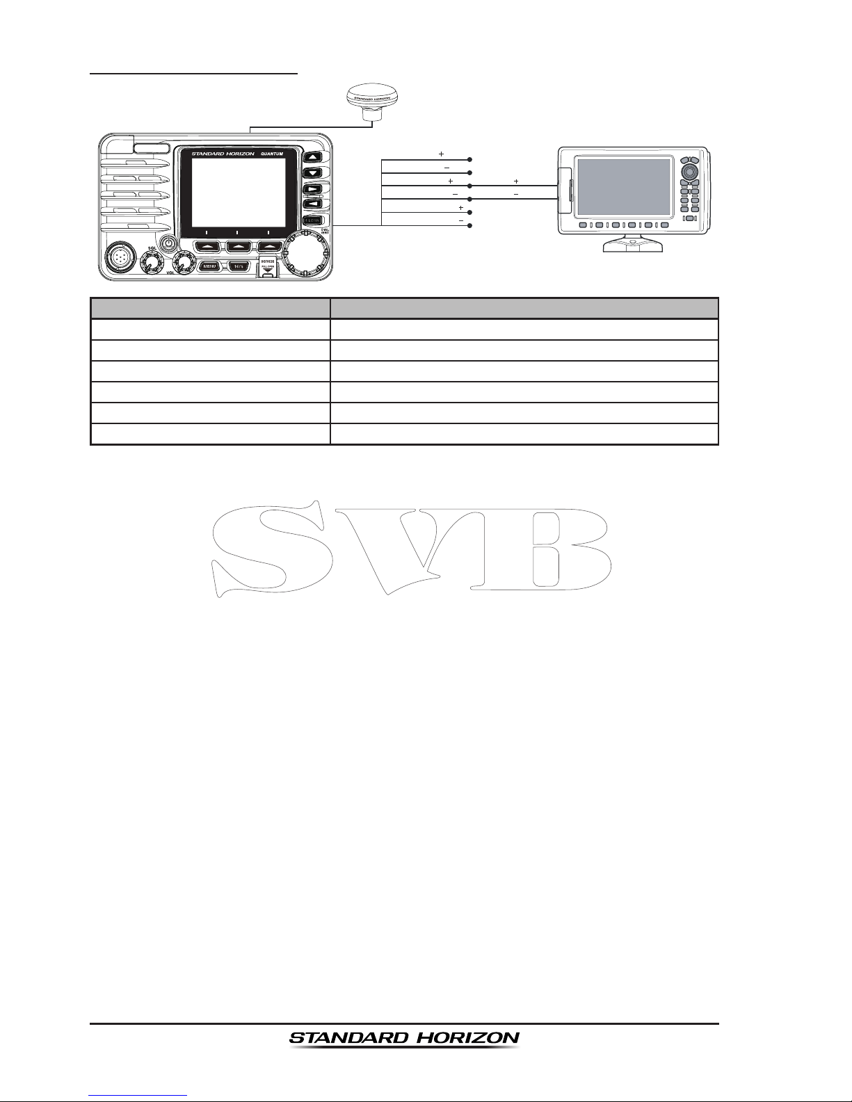
38400 Baud Connections
GPS Chart Plotter
Plotter Connection
Radio Wires
Gray: NMEA OUT
( )
Brown: NMEA OUT
( )
Yellow: NMEA-HS OUT
( )
White: NMEA-HS OUT
( )
Blue: NMEA IN
( )
NMEA IN
( )
No Connection
NMEA IN
( )
No Connection
No Connection
Green: NMEA IN
( )
No Connection
GPS Antenna
Wire Color/Description Connection Examples
BLUE - NMEA GPS Input (+) No connection
GREEN - NMEA GPS Input (−) No connection
GRAY - NMEA DSC Output (+) NMEA (+) input of GPS*
1
BROWN - NMEA DSC Output (−) NMEA (−) input of GPS*
1
YELLOW - AIS Data Output (+) No connection*
2
WHITE - AIS Data Output (−) No connection*
2
*1: The GPS chart plotter ComPort must be setup to 38400 baud (HS) to receive DSC and AIS
sentences from the GX6500E/GX6000E (Gray and Brown wires).
*2: The GX6500E/GX6000E always outputs NMEA 0183-HS VDM sentence at 38400.
Note: Some GPS chart plotters have a single wire for NMEA signal ground. In such a case connect
the NMEA input (−) to the GPS chart plotter’s single NMEA signal ground wire, and leave the NMEA
output (−) open. In case the assignment of power supply and ground of a GPS chart plotter to be
used is different from that of the radio, connect the signal ground wire of the GPS chart plotter to
the ground terminal (GND) on the rear panel of the radio.
Page 23
Page 23
GX6500E/GX6000E
5.6.5 Connection to External GPS or Chart Plotter
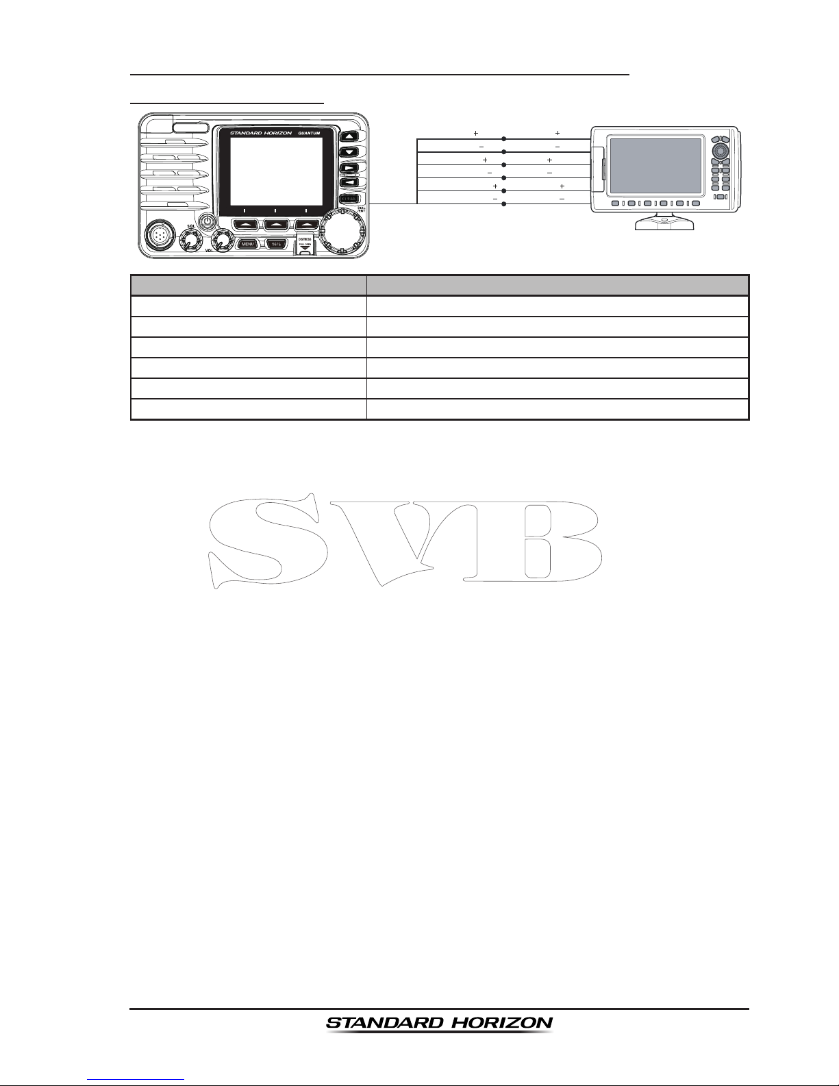
4800 Baud Connections
GPS Receiver
Plotter Connection
Radio Wires
Gray: NMEA OUT
( )
Brown: NMEA OUT
( )
Yellow: NMEA-HS OUT
( )
White: NMEA-HS OUT
( )
Blue: NMEA IN
( )
NMEA OUT
( )
NMEA OUT
( )
NMEA IN
( )
NMEA IN-HS
( )
NMEA IN
( )
NMEA IN-HS
( )
Green: NMEA IN
( )
Wire Color/Description Connection Examples
BLUE - NMEA GPS Input (+) NMEA (+) output of GPS*
1
GREEN - NMEA GPS Input (−) NMEA (−) output or common ground of GPS*
1
GRAY - NMEA DSC Output (+) NMEA (+) input of GPS*
1
BROWN - NMEA DSC Output (−) NMEA (−) input of GPS*
1
YELLOW - AIS Data Output (+) NMEA-HS (+) input of AIS receiver*
2
WHITE - AIS Data Output (−) NMEA-HS (−) input of AIS receiver*
2
*1: 4800 baud
*2: 38400 baud
Note: Some GPS chart plotters have a single wire for NMEA signal ground. In such a case connect
the NMEA input (−) to the GPS chart plotter’s single NMEA signal ground wire, and leave the NMEA
output (−) open. In case the assignment of power supply and ground of a GPS chart plotter to be
used is different from that of the radio, connect the signal ground wire of the GPS chart plotter to
the ground terminal (GND) on the rear panel of the radio.
Page 24
Page 24
GX6500E/GX6000E
38400 Baud Connections
GPS Receiver
Plotter Connection
Radio Wires
Gray: NMEA OUT
( )
Brown: NMEA OUT
( )
Yellow: NMEA-HS OUT
( )
White: NMEA-HS OUT
( )
Blue: NMEA IN
( )
NMEA OUT
( )
NMEA OUT
( )
NMEA IN
( )
No Connection
NMEA IN
( )
No Connection
Green: NMEA IN
( )
Wire Color/Description Connection Examples
BLUE - NMEA GPS Input (+) NMEA (+) output of GPS*
1
GREEN - NMEA GPS Input (−) NMEA (−) output or common ground of GPS*
1
GRAY - NMEA DSC Output (+) NMEA (+) input of GPS*
1
BROWN - NMEA DSC Output (−) NMEA (−) input of GPS*
1
YELLOW - AIS Data Output (+) No connection*
2
WHITE - AIS Data Output (−) No connection*
2
*1: The GPS chart plotter ComPort must be setup to 38400 baud (HS) to send GPS coordinates
to the GX6500E/GX6000E (Blue and Green wires) and to receive DSC and AIS sentences
from the GX6500E/GX6000E (Gray and Brown wires).
*2: The GX6500E/GX6000E always outputs NMEA 0183 VDM sentence at 38400.
Note: Some GPS chart plotters have a single wire for NMEA signal ground. In such a case connect
the NMEA input (−) to the GPS chart plotter’s single NMEA signal ground wire, and leave the NMEA
output (−) open. In case the assignment of power supply and ground of a GPS chart plotter to be
used is different from that of the radio, connect the signal ground wire of the GPS chart plotter to
the ground terminal (GND) on the rear panel of the radio.
Page 25
Page 25
GX6500E/GX6000E
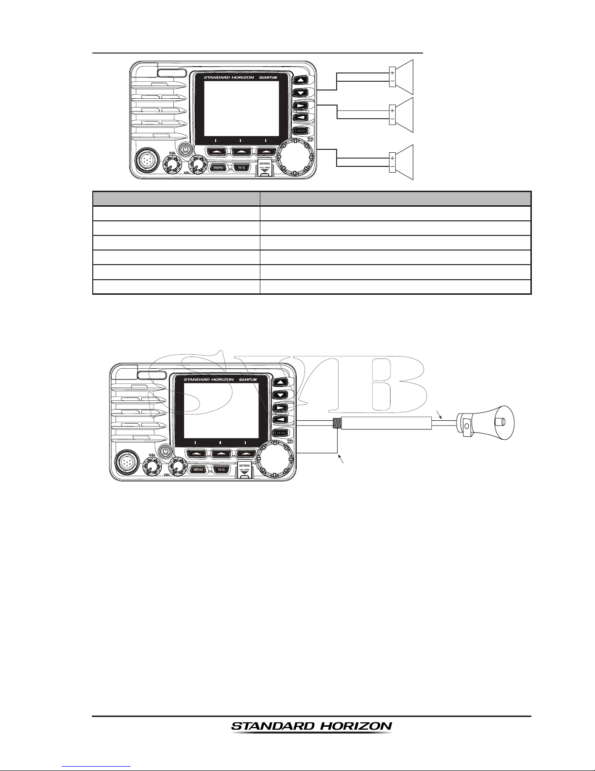
5.6.6 Connection to External PA/HAIL Speaker
PA
FWD Speaker (horn)
External Speaker
BLUE
WHITE
GREEN
RED
PA AFT Speaker (horn)
YELLOW
ORANGE
Wire Color/Description Connection Examples
RED - External Speaker (+) Positive wire of external 4 Ohm External speaker
WHITE - External Speaker (−) Negative wire of external 4 Ohm External speaker
GREEN - PA FWD Speaker (+) Positive wire of external 4 Ohm audio speaker (horn)
BLUE - PA FWD Speaker (−) Negative wire of external 4 Ohm audio speaker (horn)
ORANGE - PA AFT Speaker (+) Positive wire of external 4 Ohm audio speaker (horn)
YELLOW - PA AFT Speaker (−) Negative wire of external 4 Ohm audio speaker (horn)
In some areas powerful AM broadcast stations may be heard when in listenback mode. In this case change the speaker wire to 2-conductor shielded audio
cable. See the illustration below for connections.
Red
2 conductor shielded
Bare
Connect the shielded to GND Terminal of
the GX6500/GX6000 rear panel.
Shield of cable is not
attached on PA Sp eaker end
PA Speaker
Page 26
Page 26
GX6500E/GX6000E
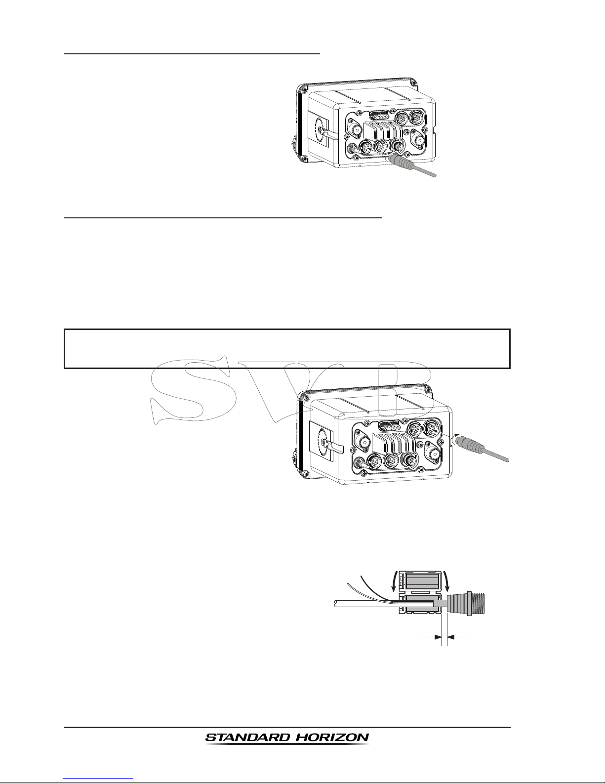
5.6.7 Rear Microphone Installation
Connect the optional MEK-4 (microphone extension kit) to the Rear MIC
(six pin) connector on the rear panel,
then tighten the cable nut (see illustration at the right).
5.6.8 Optional SSM-70H (RAM4) Installation
The GX6500E/GX6000E is capable of using two SSM-70H (RAM4) Remote
Station Microphones to remotely control the Radio, AIS, DSC and PA/Fog
functions. In addition the GX6500E/GX6000E can operate as a full function
intercom system between the SSM-70H (RAM4) and the GX6500E/GX6000E.
WARNING
Do not connect or remove the SSM-70H (RAM4) microphone while
the radio is powered on. This may result in equipment failure.
1. Connect the CT-100 extension
cable to the RAM 1 or RAM 2 (eight
pin) connector on the rear panel,
then tighten the cable nut (see
illustration at the right).
2. Install the ferrite core (supplied with the SSM-70H Remote Station Microphone) to the extension cable, then snap its two halves together, per the
illustration on the next page.
3. Attach the ferrite core as close as possible to the MIC plug, as shown below.
4. Finally, wind some plastic tape
around each ferrite core, to prevent
vibration from causing the two
halves to split apart.
As close as possible
Routing Cable or
CT-100 Extension Cable
Ferrite Core
Snap together
External Speaker
Connections
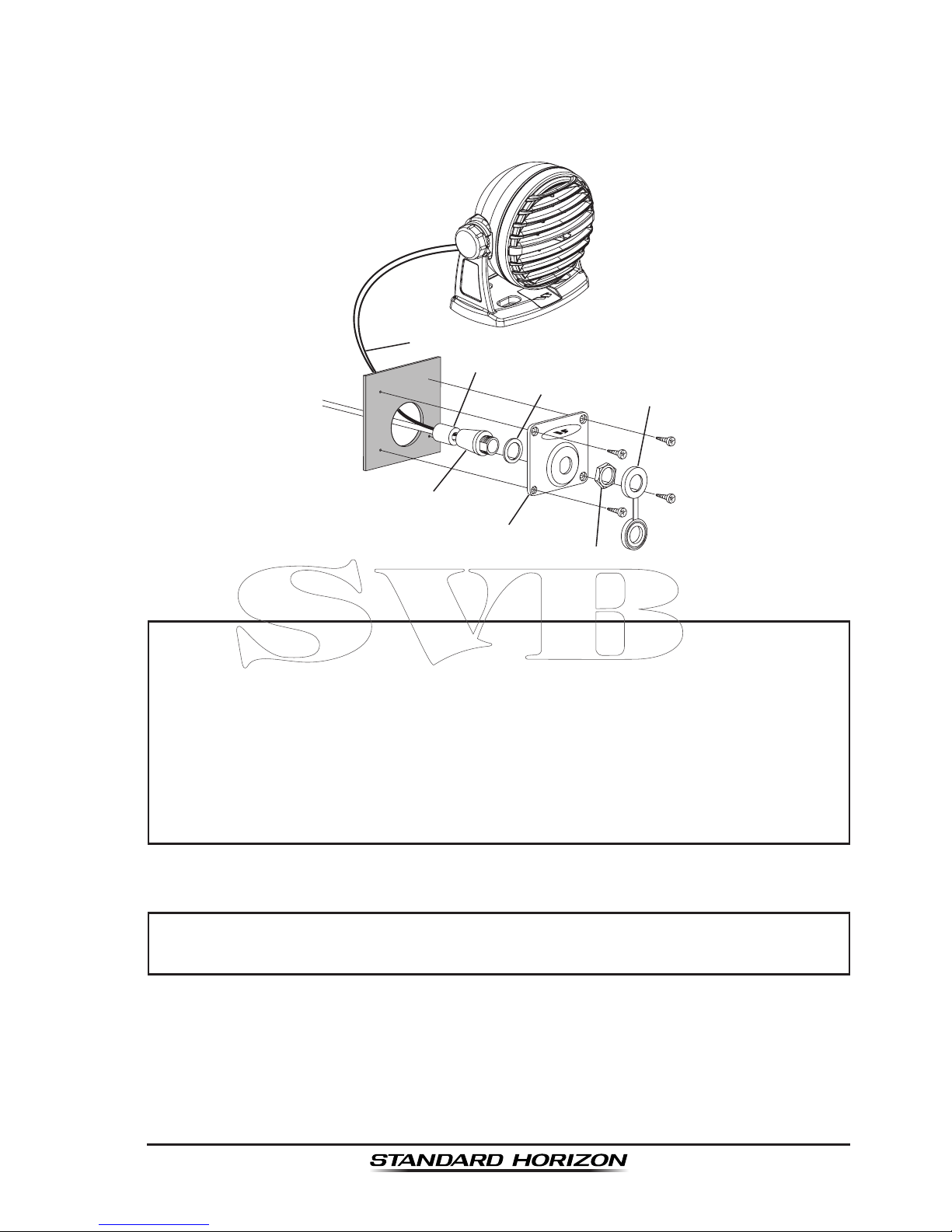
5. Referring to illustration below, make a 1.2” (30 mm) hole in the wall, then
insert the extension cable into this hole. Connect the gasket and mount
base to the extension cable connector using the nut.
Page 27
Page 27
GX6500E/GX6000E
6. Drill the four screw holes (approx. 2 mm) on the wall, then install the mounting base to the wall using four screws.
7. Put the rubber cap on to the nut. The installation is now complete.
Wall
Gasket
Mounting Bracket
Routing Cable
Cap
Nut
External Speaker Connections
Ferrite Core
NOTE
Caution!: Before cutting the cable, it must be disconnected from the rear
panel of the transceiver.
The routing cable can be cut and spliced, however care needs to be
taken when reconnecting the wires to ensure water integrity.
After cutting you will notice there are the following wires:
Yellow, White, Brown, Gray, Blue, Green, Red/White
, Shield
The red/white and shield wires are wrapped in foil. Remove the foil,
and separate the red/white and shield wires.
WARNING
It is not recommended to plug or unplug the SSM-70H (RAM4) Remote
Station Microphone into the routing cable while the radio is on.
Page 28
Page 28
GX6500E/GX6000E
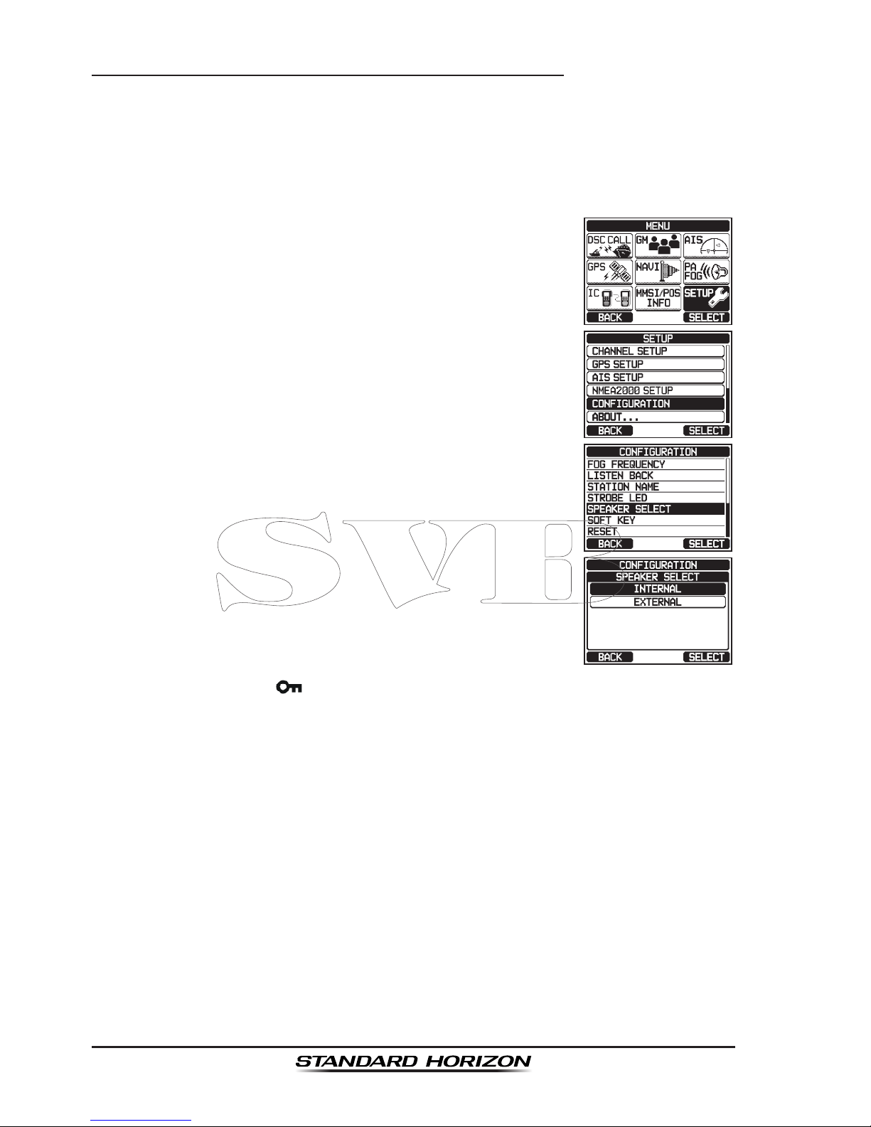
Connecting an External Speaker to the RAM4 Mic Cable
In noisy locations and optional external speaker may be connected to the white
speaker wires on the RAM4 routing cable. The RAM4 can drive the internal
speaker or the external speaker one at a time. When connecting an external
speaker, follow the procedure below to turn off the RAM4 audio and enable
the external speaker wires on the RAM4 routing cable.
1. On the RAM4 mic, press the MENU key to display
“MENU”.
c
c
2. Rotate the DIAL/ENT knob to select “SETUP”, then
press the [SELECT] soft key.
3. Rotate the DIAL/ENT knob to select “CONFIGURA-
TION”, then press the [SELECT] soft key.
4. Rotate the DIAL/ENT knob to select “SPEAKER
SELECT”, then press the [SELECT] soft key.
5. Rotate the DIAL/ENT knob to select “INTERNAL” or
“EXTERNAL”, then press the [SELECT] soft key.
6. Press the CLEAR/ key to return to radio operation.
Page 29

Page 29
GX6500E/GX6000E
5.7 INITIAL SETUP REQUIRED WHEN TURNING ON THE
POWER FOR THE FIRST TIME
5.7.1 Setting the Welcome Screen and Region
5.7.2 Maritime Mobile Service Identity (MMSI)
What is an MMSI?
An MMSI is a nine digit number used on marine transceivers capable of using
Digital Selective Calling (DSC). This number is used like a telephone number
to selectively call other vessels.
THIS NUMBER MUST BE PROGRAMMED INTO THE RADIO TO OPERATE
DSC FUNCTIONS.
How can I obtain an MMSI assignment?
In the USA, visit the following websites to register:
http://www.boatus.com/mmsi/
https://www.seatow.com/tools-and-education/mmsi
http://wireless.fcc.gov/services/index.htm?job=licensing&id=ship_stations
In Canada, visit
http://www.ic.gc.ca/epic/site/smt-gst.nsf/en/sf01032e.html
WARNING
The MMSI can be inputted only once. Therefore please be careful
not to input the incorrect MMSI number. If you need to change the
MMSI number after it has been entered, the radio will have to be returned
to Factory Service. Refer to the section “21.2 FACTORY SERVICE”.
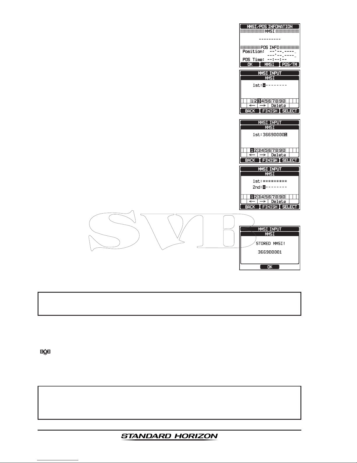
Programming the MMSI
1. Press the MENU key to display “MENU”.
2. Rotate the DIAL/ENT knob to select “MMSI/POS
INFO”, then press the [SELECT] soft key. (To cancel,
press the [BACK] soft key.)
Page 30
Page 30
GX6500E/GX6000E
3. Press the [MMSI] soft key.
4. Rotate the DIAL/ENT knob to select the rst number
of your MMSI, then press the [SELECT] soft key to
step to the next number.
5. Repeat step 4 to set your MMSI number (9 digits).
6. If a mistake was made entering in the MMSI number,
rotate the DIAL/ENT knob to select “←” or “→”, press
the [SELECT] soft key until the wrong character is
selected, then perform step 4.
7. When nished programming the MMSI number, press
the [FINISH] soft key. The radio will ask you to input
the MMSI number again. Perform steps 4 through 6
above.
8. After the second number has been input, press the
[FINISH] soft key to store the MMSI.
9. Press the [OK] soft key to return to radio operation.
NOTE
To view your MMSI after programming to ensure it is correct, perform
steps 1 to 2. Look that the MMSI number shown on the display is correct.
5.8 CHECKING GPS SIGNAL (GPS STATUS DISPLAY)
When the GX6500E/GX6000E receives the GPS signal, a small satellite icon
“ ” will appear on the display and your current location (latitude/longitude) is
shown on the display.
NOTE
If there is a problem with the NMEA connection between the radio and
the GPS, the GPS icon will blink continuously until the connection is
corrected.
Page 31

Page 31
GX6500E/GX6000E
The GX6500E/GX6000E has a GPS status display
which shows the satellites currently being received,
along with a graphical (bar-graph) representation of the
relative signal strengths from the satellites.
(gps status Display MoDe)
NOTE
For the GX6500E/GX6000E to properly show the GPS status page
when an external GPS antenna or a chart plotter is connected it must
be setup to output GSA and GSV NMEA 0183 sentences.
1. Press and hold the key to turn the radio on.
2. Press the MENU key to display “MENU”.
3. Rotate the DIAL/ENT knob to select “GPS”, then press
the [SELECT] soft key.
4. Rotate the DIAL/ENT knob to select “GPS STATUS”,
then press the [ENTER] soft key to display the GPS
status currently being received.
5. Press the CLEAR key to return to radio operation.
NOTE
When the GX6500E/GX6000E is rst turned on, it may take several
minutes to compute a x of your position. This is normal, as the
GX6500E/GX6000E is downloading “almanac” information from the
GPS satellites.
Page 32

Page 32
GX6500E/GX6000E
5.9 GPS CONFIGURATION
5.9.1 Changing the Gps Time
From the factory the GX6500E/GX6000E shows GPS satellite time or UTC
(Universal Time Coordinated) time. A time offset is needed to show the local
time in your area. The time offset must be changed in order for the radio to
display the current time in your area. See the Offset Time Table below.
offset tiMe table
1. Press the MENU key to display “MENU”.
c
c
2. Rotate the DIAL/ENT knob to select “SETUP”, then
press the [SELECT] soft key.
3. Rotate the DIAL/ENT knob to select “GPS SETUP”,
then press the [SELECT] soft key.
4. Rotate the DIAL/ENT knob to select “TIME OFFSET”,
then press the [SELECT] soft key.
5. Rotate the DIAL/ENT knob to select time offset of
your location. See illustration above to nd your offset
time. If “00:00” is assigned, the time is the same as
UTC or GPS satellite time.
6. Press the [ENTER] soft key to store the time offset.
7. Press the CLEAR key to return to radio operation.
Page 33

Page 33
GX6500E/GX6000E
5.9.2 Changing the Time Area
This menu selection allows the radio to show UTC time or local time with offset.
1. Press the MENU key to display “MENU”.
c
c
2. Rotate the DIAL/ENT knob to select “SETUP”, then
press the [SELECT] soft key.
3. Rotate the DIAL/ENT knob to select “GPS SETUP”,
then press the [SELECT] soft key.
4. Rotate the DIAL/ENT knob to select “TIME AREA”,
then press the [SELECT] soft key.
5. Rotate the DIAL/ENT knob to select “UTC” or “LOCAL”.
6. Press the [ENTER] soft key to store the selected
setting.
7. Press the CLEAR key to return to radio operation.
5.9.3 Changing the Time Format
This menu selection allows the radio to setup to show time in 12-hour or
24-hour format.
1. Press the MENU key to display “MENU”.
c
c
2. Rotate the DIAL/ENT knob to select “SETUP”, then
press the [SELECT] soft key.
3. Rotate the DIAL/ENT knob to select “GPS SETUP”,
then press the [SELECT] soft key.
4. Rotate the DIAL/ENT knob to select “TIME FORMAT”,
then press the [SELECT] soft key.
Page 34

Page 34
GX6500E/GX6000E
5. Rotate the DIAL/ENT knob to select “24hour” or
“12hour”.
6. Press the [ENTER] soft key to store the selected
setting.
7. Press the CLEAR key to return to radio operation.
5.9.4 Changing Cog to True or Magnetic
Allows the GPS COG (Course Over Ground) and the BRG from an AIS target
to be selected to show in ON or OFF. Factory default is “OFF” however by
following the steps below the COG can be changed to “ON”.
1. Press the MENU key to display “MENU”.
c
c
2. Rotate the DIAL/ENT knob to select “SETUP”, then
press the [SELECT] soft key.
3. Rotate the DIAL/ENT knob to select “GPS SETUP”,
then press the [SELECT] soft key.
4. Rotate the DIAL/ENT knob to select “MAGNETIC
VARIATION”, then press the [SELECT] soft key.
5. Rotate the DIAL/ENT knob to select “OFF” or “ON”.
6. Press the [ENTER] soft key to store the selected
setting.
7. Press the CLEAR key to return to radio operation.
NOTE
Setting to “ON” is effective only when the RMC sentences with magnetic
data are input from external devices such as a GPS receiver.
Page 35

Page 35
GX6500E/GX6000E
6 CONTROLS AND INDICATORS
This section denes each control of the transceiver. See illustration below for
location of controls. For detailed operating instructions refer to chapter 8 of
this manual.
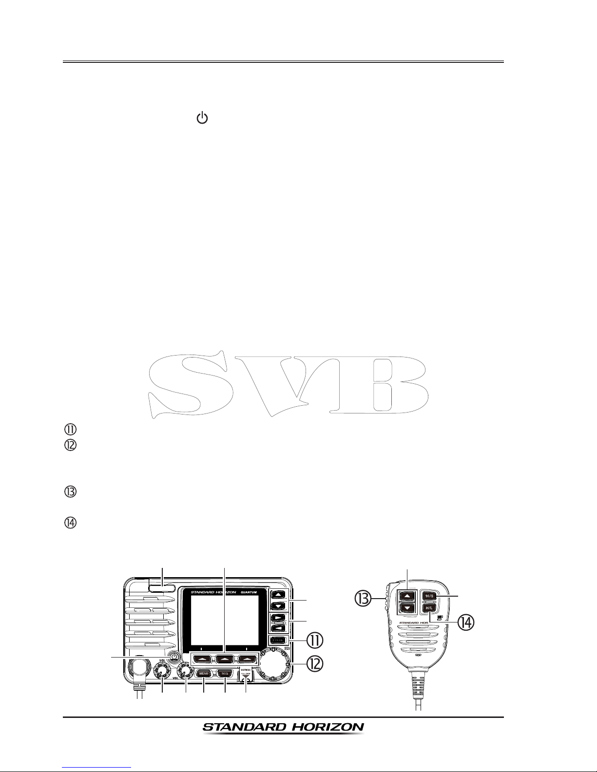
6.1 FRONT PANEL
(Power) key
Press and hold to toggle the radio on or off. When the power is turned on,
the transceiver is set to the last selected channel.
MIC Connector
Connects to the supplied speaker microphone.
SQL knob (Squelch control)
Adjusting this control clockwise, sets the point at which random noise on
the channel does not activate the audio circuits but a received signal does.
This point is called the squelch threshold. Further adjustment of the squelch
control will degrade reception of wanted transmissions.
VOL knob (Volume control)
Turns the adjusts the speaker volume.
Clockwise rotation of this knob increases the internal and speaker micro-
phone volume.
seconDary use
When in the PA or Fog mode, controls the listen-back volume.
Page 36

Page 36
GX6500E/GX6000E
MENU key
Press to access MENU. For details, refer to section “8.16 OPERATION
MENU”.
16/S key
Pressing this key immediately recalls channel 16 from any channel loca-
tion. Holding down this key recalls the SUB channel (The default setting is
channel 9). Pressing this key again reverts to the previous selected working
channel.
DISTRESS
key
Used to send a DSC Distress Call. To send the distress call, refer to section
“10.2.1 Transmitting a DSC Distress Aleart”.
Soft keys
The 3 programmable soft keys can be customized by the Setup Menu
mode described in section “15.8 SOFT KEYS”. When one of the soft keys
is pressed briey, the functions will appear above each key on the display.
▲/▼ key
These keys are used to change the operating channel. These keys on the
microphone can also be used to change the operating channel.
Press the key momentarily, the channel increases/decreases one step.
Holding the key, the channel increases/decreases continuously.
seconDary use
While the MENU screen is displayed, press the key to slide the on-screen
menu upward/downward.
When in the PA or Fog mode, press the key to change the channel.
►/◄ key
Press these keys to switch the function menu.
seconDary use
While the MENU screen is displayed, press the key to slide the on-screen
menu to the right/left side.
CLEAR key
Press this key to cancel a menu selection.
DIAL/ENT knob
While the normal screen is displayed, rotate the DIAL/ENT knob to select
your desired channel. While the MENU screen is displayed, rotate the knob
to select your desired menu item.
seconDary use
Press this knob to enter a selection in the MENU.
When in the PA or Fog mode, rotate to change the channel.
Page 37

Page 37
GX6500E/GX6000E
MODE/STATUS indicator
Indicates the radio status with the four colors on the three postions of the
mode/status indicator.
Postion Color Description
Left
Blue AIS-Board Working
Purple Receiving MSG23
Red AIS-Board Failed
Center
Red AIS Transmitting (GX6500 Only)
Orange TX Time Out (GX6500 Only)
Right
Green Data Receiving (registerd MMSI)
Orange Data Receiving (unregisterd MMSI)
Red Receive Error
DATA jack
Use the USB micro type B jack to output the NMEA data, congure the
transceiver settings and download the GPS logger data.
6.2 MICROPHONE
PTT (Push-To-Talk) switch
When in radio mode and the PTT switch is pressed, the transmitter is
enabled for voice communications to another vessel.
When PA mode is selected, pressing the PTT switch allows your voice to
be amplied and supplied to a connected PA horn.
Page 38

Page 38
GX6500E/GX6000E
When an optional RAM4 mic is connected and intercom mode is selected,
pressing the PTT switch enables voice communications from the GX6500E/
GX6000E to the RAM4 second station microphone.
Microphone speaker
Audio heard through internal radio speaker is heard through speaker inside
the microphone.
▲/▼ key
These keys on the microphone are used to select channels and to choose
menu items.
16/S key
Pressing this key immediately recalls channel 16 from any channel loca-
tion. Holding down this key recalls the SUB channel (The default setting is
channel 9). Pressing this key again reverts to the previous selected working
channel.
H/L key
Press this key to toggle between 25 W (High) and 1 W (Low) power. When
the TX output power is set to “Low” while the transceiver is on channel 13
or 67, the output power will temporarily switch from “Low” to “High” power
until the PTT switch of the microphone is released. This key is not function
on transmit inhibited and low power only channels.
Microphone
When spoken into transmits your voice with reduction of background noise,
using Clear Voice Noise Reduction Technology.
Note: Position your mouth about 1/2” (1.5 cm) away from the microphone
hole and speak in a normal voice.
Page 39

Page 39
GX6500E/GX6000E
7 BASIC OPERATION
7.1 TURNING ON AND OFF THE TRANSCEIVER
1. After the transceiver has been installed, ensure that the power supply and
antenna are properly connected.
2. Press and hold the key to turn the radio on.
3. Press and hold the key again to turn the radio off.
7.2 RECEPTION
1. Rotate the SQL knob fully counterclockwise. This state is known as “squelch
off”.
2. Turn up the VOL knob until noise or audio from the speaker is at a comfort-
able level.
3. Rotate the SQL knob, clockwise until the random noise disappears. This
state is known as the “squelch threshold”.
4. Rotate the DIAL/ENT knob to select the desired
channel. Refer to the channel chart on Pages 187
to 189 for available channels.
5. When a message is received, adjust the volume to
the desired listening level. The “[BUSY]” indicator on
the display indicates that communications are being
received.
7.3 TRANSMISSION
1. Perform steps 1 through 4 of RECEPTION.
2. Before transmitting, monitor the channel to ensure it is clear.
THIS IS AN FCC REQUIREMENT!
3. Press the microphone’s PTT (push-to-talk) switch.
The “[TX]” indicator on the LCD is displayed.
4. Speak slowly and clearly into the microphone.
5. When the transmission is nished, release the micro-
phone’s PTT switch.
NOTE
Position your mouth about 1/2” (1.5 cm) away from the microphone
hole and speak in a normal voice.
Page 40

Page 40
GX6500E/GX6000E
7.3.1 Transmit Power
The TX output power of the GX6500E/GX6000E is set to high level (25W) in
factory default, and the “[HI]” indicator is displayed on the top part of the screen.
To switch the TX output power:
1. Press the ►/◄ key repeatedly until the [HI] or [LOW]
soft key is displayed at the bottom of the screen.
2. Press the [HI] or [LOW] soft key to switch between
HI (25W) or LO (1W) output power.
When the TX output power is set to “Low” while the
transceiver is on channel 13 or 67, the output power
will temporarily switch from “Low” to “High” power until
the PTT switch of the microphone is released. This
soft key is not function on transmit inhibited and low
power only channels.
7.4 TRANSMIT TIME-OUT TIMER (TOT)
When the PTT switch on the microphone is held down, transmit time is limited
to 5 minutes. This limits unintentional transmissions due to a stuck microphone.
About 10 seconds before automatic transmitter shutdown, a warning beep will
be heard from the speaker(s). The transceiver will automatically go to receive
mode, even if the PTT switch is continually held down. Before transmitting
again, the PTT switch must rst be released and then pressed again.
NOTE
Once the transmitter is shut down by the TOT, transmission to the last
channel is only allowed 10 seconds after the shutdown.
7.5 SIMPLEX/DUPLEX CHANNEL USE
Refer to the VHF MARINE CHANNEL CHART (Pages 187 to 189) for instructions on use of simplex and duplex channels.
NOTE
All channels are factory-programmed in accordance with FCC (USA),
Industry Canada (Canada), and International regulations. Mode of
operation cannot be altered from simplex to duplex or vice-versa.
Page 41

Page 41
GX6500E/GX6000E
7.6 INTERNATIONAL, USA AND CANADA MODE
To change the channel group from International to USA or Canada:
1. Press the MENU key to display “MENU”.
c
c
2. Rotate the DIAL/ENT knob to select “SETUP”, then
press the [SELECT] soft key.
3. Rotate the DIAL/ENT knob to select “CHANNEL
SETUP”, then press the [SELECT] soft key.
4. Rotate the DIAL/ENT knob to select “CHANNEL
GROUP”, then press the [SELECT] soft key.
5. Rotate the DIAL/ENT knob to select desired channel
group “USA”, “INTL”, or “CAN”.
6. Press the [ENTER] soft key to store the selected
setting.
7. Press the CLEAR key to return to radio operation.
Page 42

Page 42
GX6500E/GX6000E
7.7 MULTI WATCH (TO PRIORITY CHANNEL)
Multi watch is used to scan two or three channels for communications.
• In Dual Watch, a normal VHF channel and the priority channel are scanned
alternately.
• In Triple Watch, a normal VHF channel, the priority channel, and the sub
channel are scanned alternately.
When a signal is received on the normal channel the radio briey switches
between the normal channel and the priority channel to look for a transmission.
If the radio receives communications on the priority channel the radio stops
and listens to priority channel until communication ends and then starts dual
or triple watch scan again.
7.7.1 Setting up the Multi Watch Operation
1. Press the MENU key to display “MENU”.
c
c
2. Rotate the DIAL/ENT knob to select “SETUP”, then
press the [SELECT] soft key.
3. Rotate the DIAL/ENT knob to select “CHANNEL
SETUP”, then press the [SELECT] soft key
4. Rotate the DIAL/ENT knob to select “MULTI WATCH”,
then press the [SELECT] soft key.
5. Rotate the DIAL/ENT knob to select “DUAL” or
“TRIPLE”.
6. Press the [ENTER] soft key to store the selected
setting.
7. Press the CLEAR key to return to radio operation.
Page 43

Page 43
GX6500E/GX6000E
7.7.2 Starting the Dual Watch
1. Adjust the SQL knob until the background noise disappears.
2. Rotate the DIAL/ENT knob to select a channel you wish to watch.
3. Press ►/◄ key repeatedly until the [DUAL WATCH]
soft key is displayed at the bottom of the screen, press
the [DUAL WATCH] soft key.
The radio will monitor the priority channel and the
channel that was selected in step 2.
If a signal is received on the channel selected in step
2, the GX6500E/GX6000E will dual watch to priority
channel.
4. To stop dual watch, press the [DUAL WATCH] soft key again.
When selecting “TRIPLE” in the SETUP menu, [TRIPLE WATCH] will be
displayed as the soft key instead of [DUAL WATCH].
NOTE
The priority channel may be changed from CH16 (default) to another
channel. Refer to section “16.7 PRIORITY CHANNEL”.
7.8 SCANNING
The GX6500E/GX6000E will automatically scan channels programmed into
the preset channel memory and also the scan channel memory, and the last
selected weather channel.
When an incoming signal is detected on one of the channels during scan, the
radio will pause on that channel, allowing you to listen to the incoming transmission. The radio will automatically start scanning again after the transmission
stops.
7.8.1 Selecting the Scan Type
1. Press the MENU key to display “MENU”.
c
c
2. Rotate the DIAL/ENT knob to select “SETUP”, then
press the [SELECT] soft key.
3. Rotate the DIAL/ENT knob to select “CHANNEL
SETUP”, then press the [SELECT] soft key
Page 44

Page 44
GX6500E/GX6000E
4. Rotate the DIAL/ENT knob to select “SCAN TYPE”,
then press the [SELECT] soft key.
5. Rotate the DIAL/ENT knob to select “PRIORITY” or
“MEMORY”.
6. Press the [ENTER] soft key to store the selected
setting.
7. Press the CLEAR key to return to radio operation.
MeMory scan (M-scan
)
CH12
CH09
CH01A
CH15
CH18
CH22A
CH61A
CH68A
CH68A
CH88A
priority scan (p-scan
)
Priority Channel
CH12
CH09
CH01A
CH15
CH18
CH22A
CH61A
CH68A
CH68A
CH88A
7.8.2 Programming Scan Memory
1. Press the MENU key to display “MENU”.
c
c
2. Rotate the DIAL/ENT knob to select “SETUP”, then
press the [SELECT] soft key.
3. Rotate the DIAL/ENT knob to select “CHANNEL
SETUP”, then press the [SELECT] soft key.
4. Rotate the DIAL/ENT knob to select “SCAN MEMORY”,
then press the [SELECT] soft key.
5. Rotate the DIAL/ENT knob to select a desired channel to be scanned, then press the [MEM] soft keys.
“ON” icon will appear at the right side of the selected
channel.
6. Repeat step 5 for all the desired channels to be
scanned.
Page 45

Page 45
GX6500E/GX6000E
7. To REMOVE a channel from the list, select the channel then press the
[MEM] soft key. “ON” icon of the selected channel will disappear.
8. When you have completed your selection, press the CLEAR key to return
to radio operation.
To check channels to be scanned, rotate the DIAL/ENT
knob. The “[MEM]” icon will appear when the memory
channel is displayed.
Note: When “SCAN MEMORY” is assigned to the soft
key, the memory function switches between on and
off every time you press the [MEM] soft key.
7.8.3 Memory Scanning (M-SCAN)
1. Set the scan type to “MEMORY” in the SETUP menu (refer to “8.9.1 Selecting
the Scan Type”).
2. Adjust the SQL knob until the background noise disappears.
3. Press the ►/◄ key repeatedly, then press the
[SCAN] soft key. “MEM SCAN” appears on the display.
Scanning will proceed from the lowest to the highest
programmed channel number and preset channel
(described in the next section) and will stop on a
channel when a transmission is received.
The channel number will blink during reception.
4. To stop scanning, press the [SCAN] soft key, 16/S or CLEAR key.
7.8.4 Priority Scanning (P-SCAN)
1. Set the scan type to “PRIORITY” in the SETUP menu (refer to “8.9.1 Selecting the Scan Type”).
2. Adjust the SQL knob until the background noise disappears.
3. Press the ►/◄ key repeatedly, then press the [SCAN]
soft key. “PRI SCAN” appears on the display. Scanning
will proceed between the memorized channels and
preset channel (described in next section) and the
priority channel.
The priority channel will be scanned after each
programmed channel.
4. To stop scanning, press the [SCAN] soft key, 16/S or CLEAR key.
Page 46

Page 46
GX6500E/GX6000E
NOTE
In the default setting, Channel 16 is set as the priority channel. You
may change the priority channel to the desired channel from Channel
16 on the SETUP menu. Refer to section “16.7 PRIORITY CHANNEL”.
7.9 PRESET CHANNELS: INSTANT ACCESS
10 preset channels can be programmed for instant access. Press the ►/◄
key repeatedly, then press the [PRESET] soft key. Pressing the [PRESET]
key activates the user assigned channel bank. If the [PRESET] soft key is
pressed and no channels have been assigned, an alert beep will be emitted
from the speaker.
Before beginning the Instant Access operation, assign the “PRESET” command
into one of the programmable keys, refer to section “15.8 SOFT KEYS”.
7.9.1 Programming
1. Rotate the DIAL/ENT knob to select the channel to
be programmed.
2. Press the ►/◄ key repeatedly to indicate the function
on the display, then press and hold the [PRESET] soft
key until the “P-SET” icon and channel number are
blinking.
3. Press the [ADD] soft key to program the channel
into the preset channel memory. “[P-SET]” icon will
appear.
4. Repeat steps 1 through 3 to program the desired
channels into the preset channels. Up to 10 channels
can be registered. If you attempt to register the 11th
channel, error beep will sound.
Page 47

Page 47
GX6500E/GX6000E
7.9.2 Operation
1. Press the ►/◄ key repeatedly, then press the
[PRESET] soft key to recall the preset channel. The
“[P-SET]” icon will appear on the display.
2. Rotate the DIAL/ENT knob to select the desired preset
channel.
3. Press the [PRESET] soft key to return to the last
selected channel. The “[P-SET]” icon will disappear
from the display.
7.9.3 Deletion
1. Press the ►/◄ key repeatedly, then press the
[PRESET] soft key to recall the preset channel.
2. Rotate the DIAL/ENT knob to select the preset channel to be deleted.
3. Press and hold the [PRESET] soft key until the
“[P-SET]” icon and channel number are blinking.
4. Press the [DELETE] soft key to delete the channel
from the preset channel memory.
5. Repeat steps 2 through 4 to delete the desired channels from preset channels.
6. To exit from deleting the preset channels, press the [QUIT] soft key.
7.10 MOB OPERATION
The GX6500E/GX6000E provides a feature to memorize the position information instantly in case of MOB (Man Over-Board).
1. Press the ►/◄ key repeatedly, then press the [MOB]
soft key.
2. Press the [TO WPT] soft key to start the navigation to
the displayed position. For details about the navigation, see section “11 NAVIGATION”.
To modify the displayed position information, press the
[POS/TM] soft key. For details about the modication,
see “Editing a Waypoint” on page 111.
Page 48

Page 48
GX6500E/GX6000E
3. To transmit a DSC distress message, lift the red spring
loaded DISTRESS cover on the right side of the
transceiver, then press and hold the DISTRESS key
(see section “10.2.1 Transmitting a DSC Distress
Aleart” for details).
The nature of the distress call is automatically set to
“MOB”.
7.11 PA/FOG OPERATION
The GX6500E/GX6000E has a 30W hailer built-in and can be used with any 4
Ohm PA horn. Standard Horizon offers two HAIL/PA horns, the 220SW (5” round
30 Watt HAIL/PA horn) and the 240SW (5” x 8” rectangular 40 Watt HAIL/PA
horn). When the GX6500E/GX6000E is in PA Hail mode the PA speaker listens
back (acts as a microphone and provides two-way communications through
the HAIL/PA horn to the main radio).
NOTE
When in the PA HAIL or FOG HORN mode, the GX6500E/GX6000E will
continue to receive DSC calls and communications on the last selected
working channel prior to entering the PA HAIL or FOG HORN mode.
Then the GX6500E/GX6000E AIS page can also be accessed when
in the PA HAIL or FOG HORN mode.
PA HAIL mode:
PA HAIL mode allows the transceiver to be used as a power hailer when
an optional STANDARD HORIZON 220SW or 240SW HAIL/PA horn is
installed. The PA Hail mode has a listen-back feature which provides two
way communication through the HAIL/PA horn.
FOG HORN mode:
Automatic signaling is transmitted through the HAIL/PA horn. When the
fog horn signal is not being outputted the GX6500E/GX6000E listens back
through the connected HAIL/PA horn.
HORN mode:
Foghorn sound or siren sound can be transmitted through the HAIL/PA horn.
When the fog horn signal is not being outputted the GX6500E/GX6000E
listens back through the connected HAIL/PA horn.
Page 49

Page 49
GX6500E/GX6000E
7.11.1 Operating the PA HAIL mode
1. Press the MENU key to display “MENU”.
c
c
2. Rotate the DIAL/ENT knob to select “PA FOG”, then
press the [SELECT] soft key.
3. Rotate the DIAL/ENT knob to select “PUBLIC
ADDRESS”, then press the [SELECT] soft key.
4. Press the microphone’s PTT switch to speak through
the HAIL/PA speaker.
Press the [PA VOL] soft key, then rotate the DIAL/
ENT knob to control the AF output level. The AF output
level can be set from 0 to 30 watts.
5. To listen back, rotate the VOL knob.
6. Press the CLEAR key to return to radio operation.
Page 50

Page 50
GX6500E/GX6000E
7.11.2 Operating the FOG HORN mode
The user can select the type of horn from “Underway”, “Stop”, “Sail”, “Towing”,
“Aground” and “Anchor”.
1. Press the MENU key to display “MENU”.
c
c
2. Rotate the DIAL/ENT knob to select “PA FOG”, then
press the [SELECT] soft key.
3. Rotate the DIAL/ENT knob to select “FOG HORN”, then
press the [SELECT] soft key.
4. Rotate the DIAL/ENT knob to select one of the six
functions described above, then press the [SELECT]
soft key.
5. On the “FOG HORN” mode, press the [FOG VOL]
soft key, then rotate the DIAL/ENT knob to control
the AF output level.
Press the [ENTER] soft key. The AF output level can
be set from 0 to 30 watts.
6. To listen back, rotate the VOL knob.
7. Press the CLEAR key to return to radio operation.
Page 51

Page 51
GX6500E/GX6000E
7.11.3 Fog Signal Timing Chart
TYPE PATTERN USAGE
UNDERWAY One 5-second blasts every 120 seconds.
5s 5s
120s
Listen Back
Motor vessel underway and
making way.
STOP Two 5-second blasts (separated by 2 seconds)
every 120 seconds.
5s 5s5s 5s
2s 2s
120s
Listen Back
Motor vessel underway but
stopped (not making way).
SAIL One 5-second blasts followed by two 1-second
blasts (separated by 2 seconds) every 120
seconds.
1s 1s1s 1s5s 5s
2s 2s2s 2s
120s
Listen Back
Sailing vessel underway, shing
vessel (underway or anchored),
vessel not under command, a
vessel restricted in her ability
to maneuver (underway or at
anchor), or a vessel towing or
pushing another ahead.
TOWING One 5-second blasts followed by three 1-second
blasts (separated by 2 seconds) every 120
seconds.
1s 1s1s 1s1s 1s5s 5s
2s 2s2s 2s2s 2s
120s
Listen Back
Vessel under tow (manned).
AGROUND One 11-second rings every 60 seconds.
1s 1s
1s
11s
1s1s1s 5s
250ms
60s
Listen Back
Vessel is aground.
ANCHOR One 5-second rings every 60 seconds.
5.25s
5s
250ms
60s
Listen Back
Vessel is at anchor.
Page 52

Page 52
GX6500E/GX6000E
7.11.4 Operating the HORN mode
The user can select the type of horn from “Horn” and “Siren”.
1. Press the MENU key to display “MENU”.
c
c
2. Rotate the DIAL/ENT knob to select “PA FOG”, then
press the [SELECT] soft key.
3. Rotate the DIAL/ENT knob to select “HORN”, then
press the [SELECT] soft key.
4. Rotate the DIAL/ENT knob to select “HORN” or “SIREN”,
then press the [SELECT] soft key.
5. On the “Horn” and “Siren” modes, press the [HORN]
soft key to activate the tone through the HAIL/PA
speaker.
Press the [FOG VOL] soft key, then rotate the DIAL/
ENT knob to control the AF output level. Press the
[ENTER] soft key. The AF output level can be set from
0 to 30 watts.
6. To listen back, rotate the VOL knob.
7. Press the CLEAR key to return to radio operation.
7.12 INTERCOM OPERATION
In addition an optional RAM4 remote station microphone must be connected to
perform intercom functions between the GX6500E/GX6000E and the RAM4.
NOTE
When using the intercom function, connect two RAM4 Remote Station
Microphones to the GX6500E/GX6000E.
7.12.1 Communication
1. Press the MENU key to display “MENU”.
c
c
2. Rotate the DIAL/ENT knob to select “IC”, then press
the [SELECT] soft key.
Page 53

Page 53
GX6500E/GX6000E
3. Rotate the DIAL/ENT knob to select the device to
which you want to communicate, then press the
[SELECT] soft key. The “” icon will appear at the
left side of the selected station.
4. Repeat step 3 for all the desired devices.
5. Press the [ENTER] soft key.
6. When the intercom mode is enabled, “INTERCOM”
is displayed on the radio and RAM4.
7. Press the microphone’s PTT switch on the radio.
“Talk” will be shown on the display.
Note: A warning beep will be heard when the radio’s
PTT and RAM4’s PTT switches are pushed at the
same time.
8. Speak slowly and clearly into the microphone, hold the microphone about
1/2” (1.5 cm) away from your mouth.
9. When nished, release the PTT switch.
10. Press the CLEAR key to return to radio operation.
7.12.2 Calling
Pressing the [BELL] soft key when in intercom mode on either the radio or
RAM4 microphone will produce a calling beep to the other station.
7.13 VOICE SCRAMBLER
The voice scrambler function for the 4-code type (CVS2500A compatible) or
the 32-code type (FVP-42 compatible for Furuno Electric FM-4721) is avail-
able by conguring optional settings (For details, consult your dealer). Refer
to the section “16.13 SCRAMBLER SETUP” to program the voice scrambler.
1. Select a channel that was programmed for scrambler
mode (the “
” icon will appear on the display).
2. Monitor the channel before transmitting.
3. Transmit the voice message. The signal sent will be
scrambled.
Page 54

Page 54
GX6500E/GX6000E
7.14 DEMO MODE
This mode is used by Standard Horizon sales persons and dealers to demonstrate radio, DSC and AIS functions. Demo mode allows latitude, longitude and
time to be entered to simulate radio displays. When the demo mode is enabled,
the radio display will automatically switch from the NORMAL, COMPASS,
WAYPOINT, AIS and GM displays.
NOTE
When demo mode is enabled and the radio is turned off and back on
the radio will still be in the demo mode.
1. Press the MENU key to display “MENU”.
c
c
2. Rotate the DIAL/ENT knob to select “SETUP”, then
press the [SELECT] soft key.
3. Rotate the DIAL/ENT knob to select “ABOUT…”, then
press the [SELECT] soft key
4. Rotate the DIAL/ENT knob to select “DEMO OPERA-
TION”, then press the [SELECT] soft key.
5. Rotate the DIAL/ENT knob to select “DEMO POSITION
INPUT”, then press the [SELECT] soft key.
6. Enter the latitude/longitude of your vessel and your
local UTC time in the 24-hour notation by the DIAL/
ENT knob. Rotate the DIAL/ENT knob to select the
number and press the [SELECT] soft key to move
the cursor to the next character.
7. If a mistake was made entering in the latitude/longitude of your vessel and
your local UTC time, rotate the DIAL/ENT knob to select “←” or “→”, press
the [SELECT] soft key until the wrong character is selected, then perform
step 6.
8. To store the data entered, press the [FINISH] soft key.
Page 55

Page 55
GX6500E/GX6000E
9. Rotate the DIAL/ENT knob to select “DEMO START”,
then press the [SELECT] soft key.
10. Rotate the DIAL/ENT knob to select “START”, then
press the [SELECT] soft key.
NOTE
To stop the demo mode, select “STOP” in step 10 above.
7.15 OPERATION MENU
The GX6500E/GX6000E provides advanced features
below, via the “MENU” screen displayed by pressing the
MENU key on the front panel.
Rotate the DIAL/ENT knob to select the desired function,
then press the [SELECT] soft key.
DSC CALL
The following seven types of DSC (Digital Selective Calling) are available:
Individual, Group, All Ships, Position Request, Position Report, Polling, and
Auto Position Polling.
This menu also provides convenient functions for DSC.
For details, refer to section “10 DIGITAL SELECTIVE CALLING (DSC)”.
GM
The GM (Group Monitor) feature performs group polling and position display
of the group members at the same time.
For details, refer to section “12 GM OPERATION”.
AIS
The ships with the AIS (Automatic Identication System) function can be
displayed using a radar chart.
For details, refer to section “13 AUTOMATIC IDENTERIFICATION SYSTEM
(AIS)”.
Page 56

Page 56
GX6500E/GX6000E
GPS
Your current location, course, and speed can be displayed in a numerical or
compass style. You can also check the position and signal strength of captured
GPS satellites.
For details, refer to section “9 GPS OPERATION”.
NAVI
You can start navigation to a memorized or temporarily input waypoint.
For details, refer to section “11 NAVIGATION”.
PA/FOG
By connecting the optional HAIL/PA speaker to the transceiver, you can output
sound such as microphone speech and foghorn sound through the HAIL/PA
speaker.
For details, refer to section “8.12 PA/FOG OPERATION”.
IC
By connecting two optional RAM4 Remote Station Microphones to the transceiver, the intercom function will become available, enabling you to talk with your
fellow passengers using the connected RAM4 Remote Station Microphones
and the supplied microphone.
For details, refer to section “8.13 INTERCOM OPERATION”.
MMSI/POS INFO
Input your MMSI (Maritime Mobile Service Identity) before you use DSC.
For details, refer to section “6.7.2 Maritime Mobile Service Identity (MMSI)”.
SETUP
This menu allows certain aspects of your transceiver’s conguration to be
customized for your personal operating conditions.
For details, refer to section “15 CONFIGURATION SETUP”.
Page 57

Page 57
GX6500E/GX6000E
8 GPS OPERATION
The GX6500E/GX6000E has the SCU-31 external GPS antenna (option) to
receive and display the position information. Your position information as well
as recieved positions can be memorized and utilized later for navigation.
8.1 DISPLAYING POSITION INFORMATION
8.1.1 GPS Information Numerical Display
1. Press the MENU key to display “MENU”.
2. Rotate the DIAL/ENT knob to select “GPS”, then press
the [SELECT] soft key.
3. Rotate the DIAL/ENT knob to select “GPS INFO”.
4. Press the [ENTER] soft key to display the numerical
display.
5. Press the CLEAR key to return to radio operation.
8.1.2 GPS Information Compass Display
1. Press the MENU key to display “MENU”.
2. Rotate the DIAL/ENT knob to select “GPS”, then press
the [SELECT] soft key.
3. Rotate the DIAL/ENT knob to select “COMPASS”.
4. Press the [ENTER] soft key to display the compass
display.
5. Press the CLEAR key to return to radio operation.
Note: Depending on the assignment of the soft keys
you may switch the screen immediately from the
basic display to the compass display by pressing the
[COMP] soft key.
Page 58

Page 58
GX6500E/GX6000E
8.2 CHECKING GPS STATUS
1. Press the MENU key to display “MENU”.
2. Rotate the DIAL/ENT knob to select “GPS”, then press
the [SELECT] soft key.
3. Rotate the DIAL/ENT knob to select “GPS STATUS”.
4. Press the [ENTER] soft key to display the GPS status
currently being received.
5. Press the CLEAR key to return to radio operation.
Page 59

Page 59
GX6500E/GX6000E
8.3 GPS LOGGER OPERATION
The GX6500E/GX6000E* includes a logger for position information that allows
you to record your location at regular intervals. (* The GX6000 requires optional
SCU-31 GPS Receiver.)
1. Press the [LOGGER] soft key to turn the function on
or off.
The recording starts and the display returns to the
previous screen with the “
” icon on the top of the
display.
• You may change the log interval time of recording
via the SETUP menu.
Note: To utilize the records, connect the GX6500E/
GX6000E to a PC and download the log data from
the radio by using the PC Programming Software.
Refer to section “20 CONNECTING A USB DATA
TERMINAL TO THE PC”.
Logger operation alert:
• When the memory for log data becomes full, three beeps will sound and a
warning message will be displayed. Afterwards the logger does not operate
until the log data in the memory are erased.
• When the logger cannot record for some reason, three beeps will sound
and a warning message will be displayed. Afterwards the logger does not
operate anymore.
• An error message will be displayed when the radio cannot erase the log data
in the memory during the operation following the alert of memory full (see
above) or in the SETUP menu (Refer to section “18.10.6 Log Erase”).
Page 60

Page 60
GX6500E/GX6000E
9 DIGITAL SELECTIVE CALLING (DSC)
9.1 GENERAL
WARNING
This GX6500E/GX6000E is designed to generate a digital maritime
distress and safety call to facilitate search and rescue. To be effective
as a safety device, this equipment must be used only within communication range of a shore-based VHF marine channel 70 distress and
safety watch system. The range of signal may vary but under normal
conditions should be approximately 20 nautical miles.
NOTE
A DSC Warning sticker is included with
the GX6500E/GX6000E. To comply with
FCC regulations this sticker must be
mounted in a location that can be easily
viewed from the location of the GX6500E/
GX6000E.
WARNING
STICKER
Digital Selective Calling (DSC) is a semi-automated method of establishing a
radio call, it has been designated by the International Maritime Organization
(IMO) as an international standard for establishing VHF, MF and HF radio
calls. It has also been designated as part of the Global Maritime Distress and
Safety System (GMDSS). It is planned that DSC will eventually replace aural
watches on distress frequencies and will be used to announce routine and
urgent maritime safety information broadcasts.
This system allows mariners to instantly send a distress call with GPS position
(when connected to the transceiver) to the Coast Guard and other vessels
within range of the transmission. DSC will also allow mariners to initiate or
receive Distress, Urgency, Safety, Routine, Position Request, and Position
Report, Automatic Position Polling, and Group calls to or from another vessel
equipped with a DSC transceiver.
Page 61

Page 61
GX6500E/GX6000E
9.2 DSC DISTRESS ALEART
The GX6500E/GX6000E is capable of transmitting and receiving DSC distress
messages to all DSC radios. Distress calls from the GX6500E/GX6000E include
the latitude and longitude of the vessel when the external GPS unit is activated.
9.2.1 Transmitting a DSC Distress Aleart
NOTE
To be able to transmit a DSC distress call an MMSI number must be
programmed, refer to section “6.7.2 Maritime Mobile Service Identity
(MMSI)”.
In order for your ships location to be transmitted, the external GPS
must be able to receive a x or a optional GPS antenna or chart plotter
must be connected. Refer to section “6.6.3 Accessory Cables and
NMEA 0183 Cables”
Basic Operation
1. Lift the red spring loaded DISTRESS cover, and press
then press and hold the DISTRESS key for 3 seconds.
The radio display will count down (3-2-1) and then
transmit the distress call. The backlight of the display
and keypad ashes while the radios display is counting down.
2. When the distress signal is sent, the transceiver
watches for a transmission on CH70 until an acknowledgment signal is received.
3. If no acknowledgment is received, the distress call is
repeated in 4 minute intervals until a DSC acknowledgment is received.
4. When a DSC distress acknowledgment is received,
a distress alarm sounds and Channel 16 is automatically selected. The display shows the MMSI of the
ship responding to your distress.
5. Press the microphone’s PTT switch and state your name, vessel name,
number of persons on board and the distress situation, then say “over” and
wait for a reply from the acknowledging ship.
Page 62

Page 62
GX6500E/GX6000E
6. To turn off the distress alarm before the radio retransmits the distress aleart,
press the 16/S key or the [QUIT] soft key.
Transmitting a DSC Distress Alert with Nature of Distress
The GX6500E/GX6000E is capable of transmitting a DSC distress alert with
the following “Nature of Distress” categories:
Undesignated, Fire/Explosion, Flooding, Collision, Grounding, Capsizing,
Sinking, Adrift, Abandoning, Piracy, MOB.
1. Press the MENU key to display “MENU”.
2. Rotate the DIAL/ENT knob to select “DSC CALL”, then
press the [SELECT] soft key.
3. Rotate the DIAL/ENT knob to select “DIST ALERT
MSG”, then press the [SELECT] soft key. (To cancel,
press the [BACK] soft key.)
4. Press the [NATURE] soft key. The “NATURE OF” menu
will appear on the display.
5. Rotate the DIAL/ENT knob to select the desired nature of distress category,
then press the [SELECT] soft key.
6. Press and hold the DISTRESS key until a distress alert is transmitted.
Transmitting a DSC Distress Alert by Manually Inputting Location and Time
In case the GX6500E/GX6000E fails to get a GPS position x, you may input
your latitude and longitude, and time to transmit the distress alert.
1. Press the MENU key to display “MENU”.
2. Rotate the DIAL/ENT knob to select “DSC CALL”, then
press the [SELECT] soft key.
3. Rotate the DIAL/ENT knob to select “DIST ALERT
MSG”, then press the [SELECT] soft key. (To cancel,
press the [BACK] soft key.)
Page 63

Page 63
GX6500E/GX6000E
4. Press the [POS/TM] soft key.
5. Rotate the DIAL/ENT knob to select the rst number
of latitude, then press the [SELECT] soft key to step
to the next number.
6. Repeat step 5 to set the position and time.
If a mistake was made, rotate the DIAL/ENT knob to
select “←” or “→”, press the [SELECT] soft key until
the wrong character is selected, then perform step 5.
7. When nished programming the position and time, press the [FINISH] soft
key. The display will return to the previous screen.
8. Press and hold the DISTRESS key until a distress alert is transmitted.
Pausing a DSC Distress Aleart
After a DSC distress call is transmitted, the DSC distress call is repeated every
4 minutes until the call is canceled by the user or until the radio is turned off
and on again. The GX6500E/GX6000E has the capability to suspend (pause)
the retransmitting of the distress call by the procedure below.
1. After the distress call is transmitted, the radio will show
the display as on the right.
Looking at this display you will notice “TX IN: 02:10”,
this is the time when the radio will re-transmit the DSC
distress call.
2. To suspend re-transmitting the DSC call, press the [PAUSE] soft key.
3. To resume counting down to transmit the DSC
Distress call, press the [RESUME] soft key.
Page 64

Page 64
GX6500E/GX6000E
Canceling a DSC Distress Aleart
If a DSC distress aleart was sent by error the GX6500E/GX6000E allows you
to send a message to other vessels to cancel the distress call that was made.
1. Press the [CANCEL] soft key, then press the [YES]
soft key.
2. After the message for cancelling has been transmitted,
press the [OK] soft key.
3. Press the [FINISH] soft key.
4. Press the [QUIT] soft key to return to radio operation.
9.2.2 Receiving a DSC Distress Aleart
1. When a DSC distress call is received, an emergency
alarm sounds.
2. Press any key to stop the alarm.
3. Rotate the DIAL/ENT knob several times to show
information on the vessel in distress.
On the display you will notice 3 soft key selections.
These selections are described below:
[ACCEPT]: Press this key to accept the DSC distress
call and to switch to Channel 16.
Note: If a key is not pressed for 30 seconds or longer the radio will auto-
matically select Channel 16. (Timer setting time is set in “AUTO CHANNEL
CHANGE” from “DSC SETUP”. The default setting is 30 sec.)
Page 65

Page 65
GX6500E/GX6000E
[PAUSE]: Press this key to temporarily disable automatic switching to
Channel 16.
[QUIT]: Press this key to quit the automatic Channel 16 switching and revert
to the last selected working channel.
4. After accepting the call, press the [TO WPT] soft
key to set the vessel in distress as a destination for
navigation.
Note: You may change the waypoint name.
5. Rotate the DIAL/ENT knob key to select “SAVE &
GOTO”, then press the [SELECT] soft key to replace
the display to the waypoint screen. The display indicates the distance and direction of the distressed
vessel, and also the compass indicates the distressed
vessel by dot ().
6. To stop navigating to a waypoint, press one of the
soft keys, then press the [STOP] soft key. The radio
is switched to the normal mode.
NOTE
• You must continue monitoring Channel 16 as a coast station may
require assistance in the rescue attempt.
• When there is an unread distress alert, “
” icon will appear on the
display. You may review the unread distress alert from the DSC log, refer
to the section “10.11.2 Reviewing a Logged DSC RX Distress Call”.
• Not all DSC radios can receive a DSC distress relay call.
Page 66

Page 66
GX6500E/GX6000E
9.3 ALL SHIPS CALL
The all ships call function allows contact to be established with DSC equipped
vessels without having their MMSI in the individual calling directory. Also, priority
for the call can be designated as “Safety” or “Urgency”.
SAFETY Call: This type of call is used to transmit boating safety information
to other vessels. This message usually contains information
about an overdue boat, debris in the water, loss of a navigation aid or an important meteorological message. This call is
the same as saying “Securite, Securite, Securite”.
URGENCY Call: This type of call is used when a vessel may not truly be in
distress, but have a potential problem that may lead to a
distress situation. This call is the same as saying “PAN PAN,
PAN PAN, PAN PAN” on Channel 16.
9.3.1 Transmitting an All Ships Call
1. Press the MENU key to display “MENU”.
2. Rotate the DIAL/ENT knob to select “DSC CALL”, then
press the [SELECT] soft key.
3. Rotate the DIAL/ENT knob to select “All SHIPS
CALL”, then press the [SELECT] soft key. (To cancel,
press the [BACK] soft key.)
4. Rotate the DIAL/ENT knob to select the nature of call
(“SAFETY” or “URGENCY”), then press the [SELECT]
soft key.
5. In the INTERSHIP CH list, rotate the DIAL/ENT knob
to select the operating channel on which you want to
communicate, then press the [SELECT] soft key. To
select operating channels from all voice channels,
press the [MANUAL] soft key.
6. Press the [YES] soft key to transmit the selected type
of all ships call.
Page 67

Page 67
GX6500E/GX6000E
7. After the all ships call is transmitted, the transceiver
will switch to the selected channel.
8. Listen to the channel to make sure it is not busy, then
key the microphone and say “PAN PAN, PAN PAN,
PAN PAN” or “Securite, Securite, Securite” depending
on the priority of the call.
9. Press the [QUIT] soft key to exit the all ships call
menu.
9.3.2 Receiving an All Ships Call
1. When an all ships call is received, an emergency
alarm will sound.
The display shows the MMSI of the vessel transmit-
ting the all ships call and the radio will change to
the requested channel after 30 seconds (the default
setting of “AUTO CHANNEL CHANGE”).
2. Press any key to stop the alarm.
3. Monitor the requested channel until the all ships voice
communication is completed.
On the display you will notice 3 soft key selections.
These selections are described below:
[ACCEPT]: Press this key to accept the DSC all ships
call and to switch to requested channel.
Note: If a key is not pressed for 30 seconds or longer the radio will auto-
matically change to the requested channel (the default setting of “AUTO
CHANNEL CHANGE”).
[PAUSE]: Press this key to temporarily disable automatic switching to the
requested channel.
Note: In some cases automatically switching to a requested channel might
disrupt important ongoing communications. This feature allows commercial users to suspend channel switching and stay on the working channel
selected before the all ships call was received.
[QUIT]: Press this key to quit the automatic channel switching and revert
to the last selected working channel.
Page 68

Page 68
GX6500E/GX6000E
4. Press the [QUIT] key to return to the channel display.
NOTE
When there is an unread all ships call, “
” icon will appear on the
display. You may review the unread all ships call from the DSC log, refer
to the section “10.11.2 Reviewing a Logged DSC RX Distress Call”.
9.4 INDIVIDUAL CALL
This feature allows the GX6500E/GX6000E to contact another vessel with
a DSC VHF radio and automatically switch the receiving radio to a desired
communications channel. This feature is similar to calling a vessel on CH16
and requesting to go to another channel (switching to the channel is private
between the two vessels). Up to 100 individual contacts may be programmed.
9.4.1 Setting up the Individual / Position Call Directory
The GX6500E/GX6000E has a DSC directory that allows you to store a vessel
or person’s name and the associated MMSI number you wish to contact via
individual calls, auto polling, position request, position report, and polling
transmissions.
To transmit an individual call you must program this directory with information
of the persons you wish to call, similar to a cellular phones telephone directory.
1. Press the MENU key to display “MENU”.
c
c
2. Rotate the DIAL/ENT knob to select “SETUP”, then
press the [SELECT] soft key.
3. Rotate the DIAL/ENT knob to select “DSC SETUP”,
then press the [SELECT] soft key.
4. Rotate the DIAL/ENT knob to select “INDIVIDUAL
DIRECTORY”, then press the [SELECT] soft key.
Page 69

Page 69
GX6500E/GX6000E
5. Rotate the DIAL/ENT knob to select “ADD”, then press
the [SELECT] soft key.
6. Rotate the DIAL/ENT knob to select “NAME:”, then
press the [SELECT] soft key.
7. Rotate the DIAL/ENT knob to scroll through the rst
letter of the name of the vessel or person you want
to reference in the directory.
8. Press the [SELECT] soft key to store the rst letter
in the name and step to the next letter to the right.
9. Repeat steps 7 and 8 until the name is complete. The name can consist of
up to fteen characters, and if you do not use all fteen characters, select
“→” to move to the next space. This method can also be used to enter a
blank space in the name.
If a mistake was made entering in the name, rotate the DIAL/ENT knob to
select “←” or “→”, press the [SELECT] soft key until the wrong character
is selected, then perform steps 7 and 8.
10. When nished entering the name (using fteen characters or less), press
the [FINISH] soft key to advance to the MMSI number entry.
11. Rotate the DIAL/ENT knob to select “MMSI:”, then press the [SELECT]
soft key.
12. Rotate the DIAL/ENT knob to scroll through numbers, 0-9. To enter the
desired number and move one space to the right by pressing the [SELECT]
soft key. Repeat this procedure until all nine space of the MMSI number are
entered.
If a mistake was made entering in the MMSI number, rotate the DIAL/ENT
knob to select “←” or “→”, press the [SELECT] soft key until the wrong
character is selected, then perform step 12.
13. When nished entering the MMSI number, press the [FINISH] soft key.
14. To store the entered data, rotate the DIAL/ENT knob
to select “SAVE”, then press the [SELECT] soft key.
15. To enter another individual address, repeat steps 5
through 14.
16. Press the CLEAR key to return to radio operation.
Page 70

Page 70
GX6500E/GX6000E
9.4.2 Setting up the Individual Call Reply
This menu item sets up the radio to automatically (default setting) or manually
respond to a DSC individual call requesting you to switch to a working channel
for voice communications. When “Manual” is selected the MMSI of the calling
vessel is shown allowing you to see who is calling. This function is similar to
caller id on a cellular phone.
1. Press the MENU key to display “MENU”.
c
c
2. Rotate the DIAL/ENT knob to select “SETUP”, then
press the [SELECT] soft key.
3. Rotate the DIAL/ENT knob to select “DSC SETUP”,
then press the [SELECT] soft key.
4. Rotate the DIAL/ENT knob to select “INDIVIDUAL
REPLY”, then press the [SELECT] soft key.
5. Rotate the DIAL/ENT knob to select “AUTO” or “MANU-
AL”.
6. Press the [ENTER] soft key to store the selected
setting.
7. Press the CLEAR key to return to radio operation.
9.4.3 Enabling the Individual Call Acknowledgment
The radio can select either reply message “Able” (default) or “Unable” when
the individual reply setting (described in the previous section) is set to “AUTOMATIC”.
1. Press the MENU key to display “MENU”.
c
c
2. Rotate the DIAL/ENT knob to select “SETUP”, then
press the [SELECT] soft key.
3. Rotate the DIAL/ENT knob to select “DSC SETUP”,
then press the [SELECT] soft key.
Page 71

Page 71
GX6500E/GX6000E
4. Rotate the DIAL/ENT knob to select “INDIVIDUAL
ACK.”, then press the [SELECT] soft key.
5. Rotate the DIAL/ENT knob to select “ABLE” or
“UNABLE”.
6. Press the [ENTER] soft key to store the selected
setting.
7. Press the CLEAR key to return to radio operation.
9.4.4 Transmitting an Individual Call
This feature allows the user to contact another vessel with a DSC radio. This
feature is similar to calling a vessel on CH16 and requesting to go to another
channel.
Individual Call using the Individual/Position Directory
1. Press the MENU key to display “MENU”.
2. Rotate the DIAL/ENT knob to select “DSC CALL”, then
press the [SELECT] soft key.
3. Rotate the DIAL/ENT knob to select “INDIVIDUAL
CALL”, then press the [SELECT] soft key. (To cancel,
press the [BACK] soft key.)
4. Rotate the DIAL/ENT knob to select “HISTORY” or
“MEMORY”, then press the [SELECT] soft key.
5. Rotate the DIAL/ENT knob to select an individual you
want to contact, press the [SELECT] soft key.
6. In the INTERSHIP CH list, rotate the DIAL/ENT knob
to select the operating channel on which you want to
communicate, then press the [SELECT] soft key. To
select operating channels from all voice channels,
press the [MANUAL] soft key.
Page 72

Page 72
GX6500E/GX6000E
7. Press the [YES] soft key to transmit the individual
DSC signal.
8. When an individual call acknowledgment is received,
the established channel is automatically changed to
the channel which is selected on step 6 above and a
ringing tone sounds.
9. Press the [QUIT] soft key to listen to the channel to
make sure it is not busy, then press the microphone’s
PTT switch and talk into the microphone to the other
vessel.
Individual Call by Manually Entering a MMSI
You may enter an MMSI number manually to contact without storing it in the
individual directory.
1. Press the MENU key to display “MENU”.
2. Rotate the DIAL/ENT knob to select “DSC CALL”, then
press the [SELECT] soft key.
3. Rotate the DIAL/ENT knob to select “INDIVIDUAL
CALL”, then press the [SELECT] soft key. (To cancel,
press the [BACK] soft key.)
4. Rotate the DIAL/ENT knob to select “MANUAL”, then
press the [SELECT] soft key.
5. Rotate the DIAL/ENT knob to select the rst number
of the MMSI which you want to contact, then press
the [SELECT] soft key to step to the next number.
6. Repeat step 5 to set the MMSI number (nine digits).
If a mistake was made entering in the MMSI number,
rotate the DIAL/ENT knob to select “←” or “→”, press
the [SELECT] soft key until the wrong character is
selected, then perform step 5.
Page 73

Page 73
GX6500E/GX6000E
7. When nished entering the MMSI number, press the [FINISH] soft key.
8. In the INTERSHIP CH list, rotate the DIAL/ENT knob
to select the operating channel on which you want to
communicate, then press the [SELECT] soft key. To
select operating channels from all voice channels,
press the [MANUAL] soft key.
9. Press the [YES] soft key to transmit the individual
DSC signal.
10. When an individual call acknowledgment is received,
the established channel is automatically changed to
the channel which is selected on step 8 above and a
ringing tone sounds.
11. Press the [QUIT] soft key to listen to the channel to
make sure it is not busy, then press the microphone’s
PTT switch and talk into the microphone to the other
vessel.
9.4.5 Receiving an Individual Call
When an individual DSC call is received, the radio will automatically respond
(default setting) to the calling ship, and switch to the requested channel for
voice communications. Refer to section “10.4.2 Setting up the Individual Call
Reply” to change the reply to manual if you want to see who is calling before
replying to the call.
Automatic reply:
1. When an individual call is received, an individual call
ringing alarm sounds.
The radio automatically switches to the requested
channel. The display shows the MMSI of the vessel
calling.
2. Press any key to stop the alarm.
3. Monitor the requested channel until the message is completed.
Press the microphone’s PTT switch and talk into the microphone to the
called vessel.
Page 74

Page 74
GX6500E/GX6000E
4. Press the [QUIT] soft key to return to radio operation.
Manual reply:
1. When an individual call is received, an individual call
ringing alarm sounds.
The display shows the MMSI of the vessel transmitting
the individual call.
2. Press any key to stop the alarm.
3. On the display you will notice 3 soft key selections.
These selections are described below:
[ACCEPT]: Press this key to accept the DSC indi-
vidual call and to switch to requested channel.
[PAUSE]: Press this key to temporarily disable auto-
matic switching to the requested channel.
Note: In some cases automatically switching to a requested channel might
disrupt important ongoing communications. This feature allows commercial users to suspend channel switching and stay on the working channel
selected before the individual call was received.
[QUIT]: Press this key to quit the automatic channel switching and revert
to the last selected working channel.
Note: If a key is not pressed for 30 seconds or longer the radio will auto-
matically change to radio operation.
4. After accepting the call, press the [ABLE] soft key to
switch to the requested channel. (To inform that you
cannot respond, press the [UNABLE] soft key.)
5. Press the [YES] soft key to send an acknowledgement.
Press the [CHG CH] soft key to change the channel
for communication from the requested one.
6. Monitor the requested or specied channel until the
message is completed.
Press the microphone’s PTT switch and talk into the microphone to the
called vessel.
Page 75

Page 75
GX6500E/GX6000E
7. Press the [QUIT] soft key to return to the channel
display.
NOTE
When there is an unread individual call, “
” icon will appear on the
display. You may review the unread individual call from the DSC log,
refer to the section “10.11.2 Reviewing a Logged DSC RX Distress
Call”.
9.4.6 Setting up the Individual Call Ringer
When an individual call is received the radio’s default setting will produce a
ringing sound for 2 minutes. This selection allows the individual call ringer time
to be changed.
1. Press the MENU key to display “MENU”.
c
c
2. Rotate the DIAL/ENT knob to select “SETUP”, then
press the [SELECT] soft key.
3. Rotate the DIAL/ENT knob to select “DSC SETUP”,
then press the [SELECT] soft key.
4. Rotate the DIAL/ENT knob to select “INDIVIDUAL
RING”, then press the [SELECT] soft key.
5. Rotate the DIAL/ENT knob to select ringing time of
individual calls.
6. Press the [ENTER] soft key to store the selected
setting.
7. Press the CLEAR key to return to radio operation.
Page 76

Page 76
GX6500E/GX6000E
The GX6500E/GX6000E has the capability to turn off the individual call ringer.
1. Press the MENU key to display “MENU”.
c
c
2. Rotate the DIAL/ENT knob to select “SETUP”, then
press the [SELECT] soft key.
3. Rotate the DIAL/ENT knob to select “DSC SETUP”,
then press the [SELECT] soft key.
4. Rotate the DIAL/ENT knob to select “DSC BEEP”, then
press the [SELECT] soft key.
5. Rotate the DIAL/ENT knob to select “INDIVIDUAL
CALL”, then press the [SELECT] soft key.
6. Rotate the DIAL/ENT knob to select “OFF”.
7. Press the [ENTER] soft key to store the selected
setting.
8. Press the CLEAR key to return to radio operation.
To re-enable the ringer tone, repeat the above procedure, rotating the DIAL/
ENT knob to select “ON” in step 6 above.
Page 77

Page 77
GX6500E/GX6000E
9.5 GROUP CALL
This feature allows the user to contact a group of specic vessels (e.g. members
of a yacht club) using DSC radios with the group call function to automatically
switch to a desired channel for voice communications. This function is very
useful for yacht clubs and vessels traveling together that want to collectively
make announcements on a predetermined channel. Up to 32 group MMSIs
may be programmed.
9.5.1 Setting up a Group Call
For this function to operate, the same group MMSI (Maritime Mobile Service
Identity Number) must be programmed into all the DSC VHF radios within the
group of vessels that will be using this feature. To understand Group MMSI
programming, rst a ship MMSI has to be understood.
Ship MMSI: The rst three digits called MID (Mobile Identity Group) of a ship
MMSI denote the country where the ship’s MMSI is registered. The last 6 digits
are specic to the ships ID.
Ship MMSI Example: If your MMSI is “366123456”, “366” is MID which denote
the country and “123456” is your ships MMSI.
Group MMSI:
Group MMSI numbers are not assigned by the FCC or other organizations
licensed to assign ship MMSI numbers.
The rst digit of a group MMSI is always set to “0” by International rules. All
Standard Horizon radios are preset so when programming a group MMSI
the rst digit is set to “0”.
The USCG recommends programming the MID of a ship MMSI into the
Second, Third and Fourth digits of the group MMSI as it denotes the area
the ship is located in.
The last 5 digits are decided upon by persons in the group. This is an impor-
tant step as all radios in the group must contain the same group MMSI so
they can be contacted by each other. There is a chance that another group
of vessels may program in the same group MMSI. If this happens, simply
change one or more of the last 5 digits of the group MMSI.
1. Press the MENU key to display “MENU”.
c
c
2. Rotate the DIAL/ENT knob to select “SETUP”, then
press the [SELECT] soft key.
Page 78

Page 78
GX6500E/GX6000E
3. Rotate the DIAL/ENT knob to select “DSC SETUP”,
then press the [SELECT] soft key.
4. Rotate the DIAL/ENT knob to select “GROUP DIREC-
TORY”, then press the [SELECT] soft key.
5. Rotate the DIAL/ENT knob to select “ADD”, then press
the [SELECT] soft key.
6. Rotate the DIAL/ENT knob to select “GROUP NAME:”,
then press the [SELECT] soft key.
7. Rotate the DIAL/ENT knob to scroll through the rst
letter of the name of the group you want to reference
in the directory.
8. Press the [SELECT] soft key to store the rst letter
in the name and step to the next letter to the right.
9. Repeat steps 7 and 8 until the name is complete. The name can consist of
up to fteen characters, if you do not use all eleven characters, select “→”
to move to the next space. This method can also be used to enter a blank
space in the name.
If a mistake was made entering in the name, rotate the DIAL/ENT knob to
select “←” or “→”, press the [SELECT] soft key until the wrong character
is selected, then perform steps 7 and 8.
10. When nished entering the group name (using fteen characters or less),
press the [FINISH] soft key to advance to the group MMSI number entry.
Page 79

Page 79
GX6500E/GX6000E
11. Rotate the DIAL/ENT knob to select “MMSI:”, then
press the [SELECT] soft key.
12. Rotate the DIAL/ENT knob to select the second
number of the MMSI (nine digits: rst digit permanently set to “0”) which you want to contact, then press
the [SELECT] soft key to step to the next number.
Repeat this procedure until all eight spaces of the
MMSI number are entered.
If a mistake was made entering in the MMSI number, rotate the DIAL/ENT
knob to select “←” or “→”, press the [SELECT] soft key until the wrong
character is selected, then perform step 12.
13. When nished entering the MMSI number, press the [FINISH] soft key to
conrm.
14. To store the data, select “SAVE”, then press the [SELECT] soft key.
15. To enter another group address, repeat steps 5 through 14.
16. Press the CLEAR key to return to radio operation.
9.5.2 Transmitting a Group Call
Group Call using the Group Directory
1. Press the MENU key to display “MENU”.
2. Rotate the DIAL/ENT knob to select “DSC CALL”, then
press the [SELECT] soft key.
3. Rotate the DIAL/ENT knob to select “GROUP CALL”,
then press the [SELECT] soft key. (To cancel, press
the [BACK] soft key.)
4. Rotate the DIAL/ENT knob to select “HISTORY” or
“MEMORY”, then press the [SELECT] soft key.
5. Rotate the DIAL/ENT knob to select a group you want
to contact, then press the [SELECT] soft key
Page 80

Page 80
GX6500E/GX6000E
6. In the INTERSHIP CH list, rotate the DIAL/ENT knob
to select the operating channel on which you want to
communicate, then press the [SELECT] soft key. To
select operating channels from all voice channels,
press the [MANUAL] soft key.
7. Press the [YES] soft key to transmit the group call
signal.
8. When the group call signal is sent, the display will be
as shown in the illustration at the right.
9. After the group call is transmitted, all the radios in the
group will switch to the designated channel.
10. Listen to the channel to make sure it is not busy, then
press the microphone’s PTT switch and call the other
vessel you desire to communicate with.
Group Call by Manually Entering an MMSI
This feature allows you to contact a group of vessels by entering in their group
MMSI manually.
1. Press the MENU key to display “MENU”.
2. Rotate the DIAL/ENT knob to select “DSC CALL”, then
press the [SELECT] soft key.
3. Rotate the DIAL/ENT knob to select “GROUP CALL”,
then press the [SELECT] soft key. (To cancel, press
the [BACK] soft key.)
4. Rotate the DIAL/ENT knob to select “MANUAL”, then
press the [SELECT] soft key.
Page 81

Page 81
GX6500E/GX6000E
5. Rotate the DIAL/ENT knob to select the rst number of
the MMSI (nine digits: rst digit permanently set to “0”)
which you want to contact, then press the [SELECT]
soft key to step to the next number.
6. Repeat step 5 to set the MMSI number.
If a mistake was made entering in the MMSI number, rotate the DIAL/ENT
knob to select “←” or “→”, press the [SELECT] soft key until the wrong
character is selected, then perform step 5.
7. When nished entering the MMSI number, press the [FINISH] soft key.
8. In the INTERSHIP CH list, rotate the DIAL/ENT knob
to select the operating channel on which you want to
communicate, then press the [SELECT] soft key. To
select operating channels from all voice channels,
press the [MANUAL] soft key.
9. Press the [YES] soft key to transmit the group call
signal.
10. After the group call is transmitted, all the radios in the
group will switch to the designated channel.
11. Listen to the channel to make sure it is not busy, then
press the microphone’s PTT switch and talk into the
microphone to the group of vessels.
Page 82

Page 82
GX6500E/GX6000E
9.5.3 Receiving a Group Call
1. When a group call is received, the GX6500E/
GX6000E will produce a ringing alarm sound.
2. The display shows the group MMSI number.
3. Press any key to stop the alarm.
4. Monitor the channel for the person calling the group
for a message.
On the display you will notice 3 soft key selections.
These selections are described below:
[ACCEPT]: Press this key to accept the group call
and to switch to requested channel.
[PAUSE]: Press this key to temporarily disable auto-
matic switching to the requested channel.
[QUIT]: Press this key to quit the automatic channel switching and revert
to the last selected working channel.
5. If you want to respond, monitor the channel to make sure it is clear, then
press the microphone’s PTT switch and talk into the microphone to the
group of vessels.
6. Press the [QUIT] soft key to return to radio operation.
Note: If a key is not pressed for 30 seconds or longer
the radio will automatically change to radio operation.
NOTE
When there is an unread group call, “
” icon will appear on the display.
You may review the unread group call from the DSC log, refer to the
section “10.11.3 Reviewing Other Logged Calls”.
Page 83

Page 83
GX6500E/GX6000E
9.5.4 Setting up the Group Call Ringer
The GX6500E/GX6000E has the capability to turn off the group call ringer.
1. Press the MENU key to display “MENU”.
c
c
2. Rotate the DIAL/ENT knob to select “SETUP”, then
press the [SELECT] soft key.
3. Rotate the DIAL/ENT knob to select “DSC SETUP”,
then press the [SELECT] soft key.
4. Rotate the DIAL/ENT knob to select “DSC BEEP”, then
press the [SELECT] soft key.
5. Rotate the DIAL/ENT knob to select “GROUP CALL”,
then press the [SELECT] soft key.
6. Rotate the DIAL/ENT knob to select “OFF”.
7. Press the [ENTER] soft key to store the selected
setting.
8. Press the CLEAR key to return to radio operation.
To re-enable the ringer tone, repeat the above procedure, rotating the DIAL/
ENT knob to select “ON” in step 6 above.
Page 84

Page 84
GX6500E/GX6000E
9.6 POSITION REQUEST
Advancements in DSC have made it possible to poll the location of another
vessel and show the position of that vessel on the display of the GX6500E/
GX6000E. Standard Horizon has taken this feature one step further, if any
compatible GPS chart plotter is connected to the GX6500E/GX6000E, the polled
position of the vessel is shown on the display of the GPS chart plotter making it
easy to navigate to the location of the polled vessel. This is a great feature for
anyone wanting to know the position of another vessel. For example your buddy
that is catching sh, or nding the location of a person you are cruising with.
NOTE
The other vessel must have an operating GPS receiver connected to its
DSC radio and must not have its radio set not to deny position requests.
(Refer the section “10.4 INDIVIDUAL CALL” to enter information into
the individual directory).
9.6.1 Setting up a Position Request Reply
The GX6500E/GX6000E can be set up to automatically (default setting) or
manually send your position when requested by another vessel. This selection
is important if you are concerned about someone polling the position of your
vessel that you may not want to. In the manual mode you will see the MMSI
(Maritime Mobile Service Identity Number) or persons name shown on the
display allowing you to choose to send your position to the requesting vessel.
1. Press the MENU key to display “MENU”.
c
c
2. Rotate the DIAL/ENT knob to select “SETUP”, then
press the [SELECT] soft key.
3. Rotate the DIAL/ENT knob to select “DSC SETUP”,
then press the [SELECT] soft key.
4. Rotate the DIAL/ENT knob to select “POSITION
REPLY”, then press the [SELECT] soft key.
Page 85

Page 85
GX6500E/GX6000E
5. Rotate the DIAL/ENT knob to select “AUTO” or
“MANUAL”. In “AUTO” mode, after a DSC POS request
is received, the radio will automatically transmit your
vessel’s position. In “MANUAL” mode, the display of
the GX6500E/GX6000E will show who is requesting
the position and the [YES] soft key on radio has to
be pressed to send your position to the requesting
vessel.
6. Press the [ENTER] soft key to store the selected setting.
7. Press the CLEAR key to return to radio operation.
9.6.2 Transmitting a Position Request to Another Vessel
Position Request using the Individual/Position Directory
Refer to section “10.4 INDIVIDUAL CALL” to enter information into the individual directory.
1. Press the MENU key to display “MENU”.
2. Rotate the DIAL/ENT knob to select “DSC CALL”, then
press the [SELECT] soft key.
3. Rotate the DIAL/ENT knob to select “POS REQUEST
CALL”, then press the [SELECT] soft key.
4. Rotate the DIAL/ENT knob to select “HISTORY” or
“MEMORY”, then press the [SELECT] soft key.
5. Rotate the DIAL/ENT knob to select a name that was
stored in the individual/position directory.
6. Press the [SELECT] soft key, then press the [YES]
soft key to transmit the position request DSC call.
7. When the GX6500E/GX6000E receives the position
from the polled vessel it is shown on the radio display.
Page 86

Page 86
GX6500E/GX6000E
8. Press the [QUIT] soft key to return to radio operation.
NOTE
If the GX6500E/GX6000E does not receive position data from the polled
vessel, the display will show “NO POSITION DATA”.
Position Request by Manually Entering an MMSI
This feature allows you to request the position of a vessel by manually entering the MMSI.
1. Press the MENU key to display “MENU”.
2. Rotate the DIAL/ENT knob to select “DSC CALL”, then
press the [SELECT] soft key
3. Rotate the DIAL/ENT knob to select “POS REQUEST
CALL”, then press the [SELECT] soft key.
4. Rotate the DIAL/ENT knob to select “MANUAL”, then
press the [SELECT] soft key.
5. Rotate the DIAL/ENT knob to select the rst number
of the MMSI (nine digits) which you want to contact,
then press the [SELECT] soft key to step to the next
number.
6. Repeat step 5 to set the MMSI number.
If a mistake was made entering in the MMSI number, rotate the DIAL/ENT
knob to select “←” or “→”, press the [SELECT] soft key until the wrong
character is selected, then perform step 5.
7. When nished entering the MMSI number, press the [FINISH] soft key.
Page 87

Page 87
GX6500E/GX6000E
8. Press the [YES] soft key to transmit the position
request DSC call.
9. When the GX6500E/GX6000E receives the position
from the polled vessel it is shown on the radio display.
10. Press the [QUIT] soft key to return to radio operation.
NOTE
The received position from the polled vessel can be transferred to a
GPS chart plotter via NMEA DSC and DSE sentences.
9.6.3 Receiving a Position Request
1. When a position request call is received from another
vessel, a ringing sound will be produced, and the
display will be as shown in the illustration at the right.
2. Press any key to stop the alarm.
3. To send your vessel’s position to the requesting
vessel, press the [REPLY] soft key.
Or to exit from position request display, press the
[QUIT] soft key.
4. Press the [QUIT] soft key to return to the channel
display.
NOTE
When there is an unread position request call, “
” icon will appear on
the display. You may review the unread individual call from the DSC
log, refer to the section “10.11.3 Reviewing Other Logged Calls”.
Page 88

Page 88
GX6500E/GX6000E
9.6.4 Manual Input of Position Information
If the GX6500E/GX6000E is located in an area where GPS reception is limited
when you are going to reply to the received position request, you may manually
input your location (latitude and longitude) and time to be sent.
1. Press the MENU key to display “MENU”.
2. Rotate the DIAL/ENT knob to select “MMSI/POS
INFO”, then press the [SELECT] soft key.
3. Press the [POS/TM] soft key.
4. Rotate the DIAL/ENT knob to select the rst number
of latitude, then press the [SELECT] soft key to step
to the next number.
5. Repeat step 4 to set the position and time.
If a mistake was made, rotate the DIAL/ENT knob to
select “←” or “→”, press the [SELECT] soft key until
the wrong character is selected, then perform step 4.
6. When nished programming the position and time, press the [FINISH] soft
key. The display will return to the previous screen.
7. Press the [OK] soft key.
8. Press the CLEAR key to return to radio operation.
Page 89

Page 89
GX6500E/GX6000E
9.6.5 Setting up a Position Request Ringer
The GX6500E/GX6000E has the capability to turn off the position request ringer.
1. Press the MENU key to display “MENU”.
c
c
2. Rotate the DIAL/ENT knob to select “SETUP”, then
press the [SELECT] soft key.
3. Rotate the DIAL/ENT knob to select “DSC SETUP”,
then press the [SELECT] soft key.
4. Rotate the DIAL/ENT knob “DSC BEEP”, then press
the [SELECT] soft key.
5. Rotate the DIAL/ENT knob to select “POS REQUEST”,
then press the [SELECT] soft key.
6. Rotate the DIAL/ENT knob to select “OFF”.
7. Press the [ENTER] soft key to store the selected
setting.
8. Press the CLEAR key to return to radio operation.
To re-enable the ringer tone, repeat the above procedure, rotating the DIAL/
ENT knob to select “ON” in step 6 above.
Page 90

Page 90
GX6500E/GX6000E
9.7 POSITION REPORT
The feature is similar to position request, however instead of requesting a
position of another vessel this function allows you to send your position to
another vessel.
9.7.1 Transmitting a DSC Position Report Call
DSC Position Report Call using the Individual/Position Directory
Refer to section “10.4 INDIVIDUAL CALL” to enter information into the individual directory.
1. Press the MENU key to display “MENU”.
2. Rotate the DIAL/ENT knob to select “DSC CALL”, then
press the [SELECT] soft key.
3. Rotate the DIAL/ENT knob to select “POS REPORT CALL”,
then press the [SELECT] soft key. (To cancel, press
the [BACK] soft key.)
4. Rotate the DIAL/ENT knob to select “HISTORY” or
“MEMORY”, then press the [SELECT] soft key.
5. Rotate the DIAL/ENT knob to select the name in the
directory, then press the [SELECT] soft key.
6. If you want to change the position displayed, press the
[POS/TM] soft key to go to the position information
input screen. After inputting new position information,
press the [FINISH] soft key to conrm.
7. Press the [YES] soft key to send your position to the selected vessel.
8. Press the [QUIT] soft key to return to radio operation.
Page 91

Page 91
GX6500E/GX6000E
DSC Position Report Call by Manually Entering an MMSI
This feature allows you to send your position to another vessel by manually
entering the MMSI of the ship you want to send your position to.
1. Press the MENU key to display “MENU”.
2. Rotate the DIAL/ENT knob to select “DSC CALL”, then
press the [SELECT] soft key.
3. Rotate the DIAL/ENT knob to select “POS REPORT
CALL”, then press the [SELECT] soft key. (To cancel,
press the [BACK] soft key.)
4. Rotate the DIAL/ENT knob to select “MANUAL”, then
press the [SELECT] soft key.
5. Rotate the DIAL/ENT knob to select the rst number
of the MMSI which you want to contact, then press
the [SELECT] soft key to step to the next number.
6. Repeat step 5 to set the MMSI number.
If a mistake was made entering in the MMSI number,
rotate the DIAL/ENT knob to select “←” or “→”, press
the [SELECT] soft key until the wrong character is
selected, then perform step 5.
7. When nished entering the MMSI number, press the [FINISH] soft key.
8. If you want to change the position displayed, press the [POS/TM] soft key
to go to the position information input screen. After inputting new position
information, press the [FINISH] soft key to conrm.
9. Press the [YES] soft key to send your position to the
selected vessel.
10. Press the [QUIT] soft key to return to radio operation.
Page 92

Page 92
GX6500E/GX6000E
9.7.2 Receiving a DSC Position Report Call
When another vessel transmits their vessels location to the GX6500E/GX6000E
the following will happen:
1. When a position report call is received from another
vessel, a ringing sound will be produced.
2. Press any key to stop ringing.
3. Press the [INFO] soft key to see more detailed position information of the station.
4. To exit to radio mode, press the [QUIT] soft key.
9.7.3 Navigating to the Reported Position
The GX6500E/GX6000E has a feature that allows you to navigate to a received
position report call by using the compass display. Navigating to the position of
a position report call may be enabled by the procedure below.
1. After the position report call has been received, press
the [INFO] soft key.
2. Press the [WPT] soft key.
3. The display indicates the distance and direction of the
received vessel, and also the compass indicates the
received vessel with a dot ().
Page 93

Page 93
GX6500E/GX6000E
Stopping Navigation to the Reported Position
1. Press one of the soft keys to show the key selections.
2. Press the [STOP] soft key. The radio will stop navigating to the waypoint and the normal VHF display will
be shown.
9.7.4 Saving the Reported Position as a Waypoint
The GX6500E/GX6000E can save a position report call in the radio’s memory
as a waypoint.
1. After the position report call has been received, press
the [SAVE] soft key.
2. If you want to change the name of the waypoint, rotate
the DIAL/ENT knob to select “NAME”, then press the
[SELECT] soft key.
3. Enter the name of the waypoint you want to reference
in the directory. For details, refer to “10.4.1 Setting
up the Individual / Position Call Directory”.
4. Rotate the DIAL/ENT knob to select “SAVE”, then
press the [SELECT] soft key to save the waypoint
into memory.
5. Press the [OK] soft key to return to the position report
display.
Navigating to a Saved Waypoint
Refer to section “11.1.1 Starting and Stopping Navigation” for details.
Page 94

Page 94
GX6500E/GX6000E
9.7.5 Setting up a Position Report Ringer
The GX6500E/GX6000E has the capability to turn off the position report ringer.
1. Press the MENU key to display “MENU”.
c
c
2. Rotate the DIAL/ENT knob to select “SETUP”, then
press the [SELECT] soft key.
3. Rotate the DIAL/ENT knob to select “DSC SETUP”,
then press the [SELECT] soft key.
4. Rotate the DIAL/ENT knob to select “DSC BEEP”, then
press the [SELECT] soft key.
5. Rotate the DIAL/ENT knob to select “POS REPORT”,
then press the [SELECT] soft key.
6. Rotate the DIAL/ENT knob to select “OFF”.
7. Press the [ENTER] soft key to store the selected
setting.
8. Press the CLEAR key to return to radio operation.
To re-enable the ringer tone, repeat the above procedure, rotating the DIAL/
ENT knob to select “ON” in the step 6 above.
Page 95

Page 95
GX6500E/GX6000E
9.8 POLLING CALL
The GX6500E/GX6000E has the capability to track another vessel.
9.8.1 Transmitting a Polling Call to a Vessel
Polling Call using the Individual/Position Call Directory
1. Press the MENU key to display “MENU”.
2. Rotate the DIAL/ENT knob to select “DSC CALL”, then
press the [SELECT] soft key.
3. Rotate the DIAL/ENT knob to select “POLLING CALL”,
then press the [SELECT] soft key.
4. Rotate the DIAL/ENT knob to select “HISTORY” or
“MEMORY”, then press the [SELECT] soft key.
5. Rotate the DIAL/ENT knob to select a name that was
stored in the individual/position call directory, then
press the [SELECT] soft key.
6. Press the [YES] soft key to transmit the polling call.
7. After a polling call is transmitted, if the reply signal
is not received, “Waiting for ACK” is shown on
the display which means the GX6500E/GX6000E is
waiting for the vessel you called to send an acknowledgement.
8. To transmit the call again, press the [RESEND] soft
key.
9. Press the [QUIT] soft key to return to radio operation.
Page 96

Page 96
GX6500E/GX6000E
Polling Call by Manually Entering an MMSI
This feature allows you to contact a vessel by manually entering the MMSI of
the ship you want to track.
1. Press the MENU key to display “MENU”.
2. Rotate the DIAL/ENT knob to select “DSC CALL”, then
press the [SELECT] soft key.
3. Rotate the DIAL/ENT knob to select “POLLING CALL”,
then press the [SELECT] soft key.
4. Rotate the DIAL/ENT knob to select “MANUAL”, then
press the [SELECT] soft key.
5. Rotate the DIAL/ENT knob to select the rst number
in the MMSI and press the [SELECT] soft key.
6. Repeat step 5 until all the digits of the MMSI are shown
on the display.
7. If a mistake was made entering in the MMSI number,
rotate the DIAL/ENT knob to select “←” or “→”, press
the [SELECT] soft key until the wrong character is
selected, then perform step 5.
8. When nished entering the MMSI number, press the [FINISH] soft key.
9. Press the [YES] soft key to transmit the polling call.
10. Press the [QUIT] soft key to return to radio operation.
Page 97

Page 97
GX6500E/GX6000E
9.8.2 Receiving a Polling Call
When another vessel transmits a polling call to the GX6500E/GX6000E the
following will happen:
1. When a polling call is received, the radio will automatically respond to the calling vessel.
2. To exit from the polling call display, press the [QUIT]
soft key.
9.9 AUTO POSITION POLLING
The GX6500E/GX6000E has the capability to automatically track seven vessels
programmed into the individual directory, or to automatically send your position
information to the programmed stations.
9.9.1 Setting up the Polling Operation
1. Press the MENU key to display “MENU”.
c
c
2. Rotate the DIAL/ENT knob to select “SETUP”, then
press the [SELECT] soft key.
3. Rotate the DIAL/ENT knob to select “DSC SETUP”,
then press the [SELECT] soft key.
4. Rotate the DIAL/ENT knob to select “AUTO POSITION
POLLING”, then press the [SELECT] soft key.
5. Rotate the DIAL/ENT knob to select the desired
operation (AUTO POS REQUEST and AUTO POS
REPORT), and press the [ENTER] soft key.
6. Press the CLEAR key to return to radio operation.
Page 98

Page 98
GX6500E/GX6000E
9.9.2 Setting up the Polling Time Interval
1. Press the MENU key to display “MENU”.
c
c
2. Rotate the DIAL/ENT knob to select “SETUP”, then
press the [SELECT] soft key.
3. Rotate the DIAL/ENT knob to select “DSC SETUP”,
then press the [SELECT] soft key.
4. Rotate the DIAL/ENT knob to select “AUTO POS
INTERUAL”, then press the [SELECT] soft key.
5. Rotate the DIAL/ENT knob to select the desired
interval time (30 second, 1, 2, 3, and 5 minutes) and
press the [ENTER] soft key.
6. Press the CLEAR key to return to radio operation.
9.9.3 Selecting Vessels to be Automatically Polled
NOTE
The radio uses the individual directory to select vessels to be automatically polled. Refer to section “10.4.1 Setting up the Individual /
Position Call Directory” and to enter MMSI of vessels you want to
poll before proceeding.
1. Press the MENU key to display “MENU”.
2. Rotate the DIAL/ENT knob to select “DSC CALL”, then
press the [SELECT] soft key.
3. Rotate the DIAL/ENT knob to select “AUTO POS POLL-
ING”, then press the [SELECT] soft key.
Page 99

Page 99
GX6500E/GX6000E
4. Rotate the DIAL/ENT knob to select “SELECTED ID”,
then press the [SELECT] soft key.
5. The radio will show a blank row highlighted when you
select the vessel for the rst time. Press the [SELECT]
soft key.
6. The radio will show the vessels programmed in the
individual directory. Rotate the DIAL/ENT knob to
select the desired vessel, then press the [ENTER]
soft key.
7. For more entries, rotate the DIAL/ENT knob to select a
blank row, press the [SELECT] soft key, then perform
step 6.
8. When nished, press the CLEAR key to exit to the
radio mode.
9.9.4 Enabling/Disabling Auto POS Polling
1. Press the MENU key to display “MENU”.
2. Rotate the DIAL/ENT knob to select “DSC CALL”, then
press the [SELECT] soft key.
3. Rotate the DIAL/ENT knob to select “AUTO POS POLL-
ING”, then press the [SELECT] soft key.
4. Rotate the DIAL/ENT knob to select the “ACTIVA-
TION”, then press the [SELECT] soft key.
5. Rotate the DIAL/ENT knob to select “START” to enable
transmissions or “STOP” to disable, then press the
[ENTER] soft key.
6. Press the CLEAR key to return to radio operation.
Page 100

Page 100
GX6500E/GX6000E
7. Auto POS Polling starts and “[A]” icon will light up on
the screen.
9.10 DSC TEST
This function is used to contact another DSC equipped vessel to ensure the
DSC functions of the radio are operating.
NOTE
To use this feature, the radio that will receive the test call also needs
to have the DSC Test feature.
To perform the DSC test you will need to enter a MMSI of another vessel into the
individual directory or manually enter in the MMSI using the procedure below.
9.10.1 Programming MMSI into Individual Directory
Refer to section “10.4.1 Setting up the Individual / Position Call Directory”.
9.10.2 Transmitting a DSC Test to Another Vessel
DSC Test call by using Individual/Position Directory
1. Press the MENU key to display “MENU”.
2. Rotate the DIAL/ENT knob to select “DSC CALL”, then
press the [SELECT] soft key.
3. Rotate the DIAL/ENT knob to select “DSC TEST CALL”,
then press the [SELECT] soft key.
4. Rotate the DIAL/ENT knob to select “HISTORY” or
“MEMORY”, then press the [SELECT] soft key.
5. Rotate the DIAL/ENT knob to select the ship name,
then press the [SELECT] soft key.
 Loading...