

Page 1
MST70
Marine AM/FM Cassette
Stereo System
With NOAA Weather
Owner's Manual
Marine Division of Yaesu U.S.A.
Page 2

TABLE OF CONTENTS
FEATURES............................................................................................1
REPLACEMENT PARTS.......................................................................2
LISTENING TO FM ON YOUR BOAT...................................................2
CASSETTE CARE AND MAINTENANCE.............................................2
REMOVING AND FITTING THE FRONT PANEL.................................3
INSTALLATION.....................................................................................4
Mounting..........................................................................................4
Upright or Overhead Mounting........................................................4
Flush Mounting...................................................
Electrical Wiring.........................................
Speaker Connections.......................................................................8
Antenna Connections....................................................
Fuse Replacement............................................................................9
CONTROLS...........................................................................................9
OPERATION........................................................................................10
General Functions..........................................................................10
Radio..............................................................................
Reset..............................................................................................13
Cassette Player..............................
SPECIFICATIONS...............................................................................15
ACCESSORIES...................................................................................16
LIMITED WARRANTY.........................................................................17
..................................................14
..............................5
......................................7
...................9
.................11
Page 3

FEATURES
• Detachable Face Panel: Guards against theft by allowing you to remove
the face panel, rendering the player unusable. A carry case for the
detachable face panel is included.
• All Electronic Controls: The Bass, Treble, Volume, Balance and Fader
functions are all controlled by touch buttons for greater long term reliability.
• 30 Pre-set Memories: Store up to 18 FM and 12 AM stations in memory
for easy recall.
• Auto Pre-set Memory System: Automatically locates and stores local
stations into memory for you.
• Seek and Manual Tuning: Select stations yourself or let your radio find
them for you.
• Local/DX Switch: Adjusts your radio's sensitivity for distant or local
reception when seeking or scanning.
• Backlighting: Special 'night vision' orange back lighting of the display
and all controls.
• Built in Clock: Automatically displays the time when the unit is switched
off, and at the press of a button when using the radio or cassette player.
• FM Stereo/Mono Switch: Lets you manually disable stereo operation for
improved FM reception in weak signal areas.
• RCA Outputs: Provides a separate low level output for connection to
external equalizer/booster-amplifier systems.
• Water Resistant Housing: Built into a special water resistant marine
housing made from corrosion proof materials with a transparent splashresistant front cover.
• Hi Output Power: 25 Watts peak to peak output power per channel.
• Large easy to read LCD: Displays station memories, frequency, time and
selected functions.
• NOAA Weather Channels: Fitted with 10 weather channels for instant
access to local weather reports.
MST70 Owner’s Manual Page 1
Page 4

REPLACEMENT PARTS
PART STANDARD HORIZON PART NUMBER
Dust Cover.......................................................................................053002027A
Flush Mount Escutcheon.................................................................063002002A
Mounting Bracket............................................................................160004023A
Mounting Bracket Knobs.................................................................154011017A
Power Wire Harness........................................................................156007001A
Rear Case Assembly......................................................................M32649001A
Speaker Wire Harness.....................................................................156008001A
LISTENING TO FM ON YOUR BOAT
The majority of FM broadcasts are music programs. Compared with AM
signals, FM signals have a wider dynamic range, are relatively immune to noise
and provide virtually distortion free music reproduction. However, because of
the nature of FM signals and the fact that FM stations are usually positioned for
shore base reception, receiving them in a moving boat may be accompanied
by problems.
• FM programs are broadcast for local reception and cannot be heard at
distant locations. To enjoy FM programs at their best, it is important that
you tune to a station that is broadcasting locally.
• FM signals can reflect from solid objects such as buildings or hills. If these
reflected signals are received along with signals arriving directly from the
transmitter, they may mix together to produce what is known as 'multipath
distortion'. This distortion is heard as noise. Often moving as little as 3 feet
from your position will correct this problem.
• FM signals travel in straight lines. Because the signals are reflected from or
absorbed by large solid objects, a signal 'shadow' may be present behind
the object which may result in poor reception in that area.
CASSETTE CARE AND MAINTENANCE
1. Tapes no longer than C-90 (90 minutes playing time) are recommended.
Avoid using C-120 tapes because they are extremely thin and may jam
your cassette player mechanism.
2. The most common cause of poor sound reproduction is a contaminated
tape head. Signs of contamination include low volume on one or both
channels and failure to produce high frequency notes. The head can be
cleaned using a cotton applicator soaked in alcohol. If the cassette unit is
used for more than one hour each day, the head should be cleaned once
or twice a month.
Page 4 Owner’s Manual MST70Page 2 Owner’s Manual MST70
Page 5
3. To extend the life of your cassettes, keep them away from:
S
E
K
• areas exposed to the sun
• top of instrument panels
• the engine
• areas exposed to heat and moisture
• magnetic fields (such as speakers)
4. Replace tapes in their plastic cases when not in use.
5. Do not oil revolving parts.
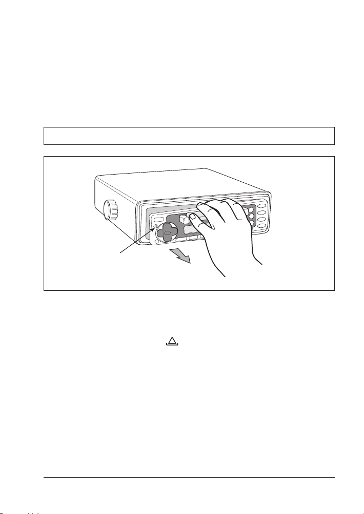
REMOVAL AND FITTING THE FACE PANEL
Release
Button
Removal
Before removing the face panel, turn the unit OFF by pressing the POWER
button.
1. Press the release button to release the left-hand end of the
face panel.
2. Lift the front panel out towards you.
After removing the face panel, place it inside the supplied case to protect
it from damage. Do not leave it in a position where it could be exposed to
direct sunlight.
MST70 Owner’s Manual Page1
MST70 Owner’s Manual Page 3
Page 6
Refitting
1. Make sure the face panel is the right way up as it cannot be attached
upside down.
2. Fit the right-hand end of the face panel into the tabs inside the right-hand
end of the unit.
3. Gently press the left-hand end of the face panel into place until it clicks.
Only light pressure is required.
INSTALLATION
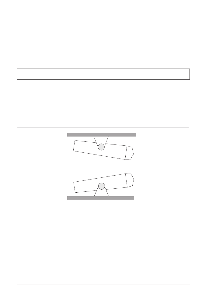
Mounting
The MST70 is designed to be mounted in several different ways so that it can
be installed in the most convenient position. Although the MST70 is water
resistant when the front cover is closed, care should be taken to locate
it where it will not be subjected to spray or rain. The diagrams below show
the various methods of bracket mounting available.
Overhead Mount
Upright Mount
Upright or Overhead Mounting
1. Attach the two gimbal knobs and self-adhesive rubber washers to the
MST70 and slide the unit into the mounting bracket. Ensure the rubber
washers are between the bracket and the radio. Tighten the knobs firmly.
2. Temporarily position the MST70 in the desired location, tilting the radio
in the bracket to ensure you are able to get the required adjustments for
viewing angle etc.
3. Roughly mark the location of the bracket edges, then seperate the radio
from the bracket and reposition the bracket to mark the mounting hole
positions. A range of mounting holes are provided to suit most installations.
Page 4 Owner’s Manual MST70
Page 7

4. Screw or bolt the bracket into position. The mounting method will depend
IMPORTANT DRAW
AROUND THIS EDGE
70 mm
200 mm
on the material to which the bracket is being attached.
5. Slide the MST70 back into the bracket slots and adjust to the required
position before tightening the gimbal knobs.
6. Connect the antenna lead and electrical wiring as described later.
Flush Mounting
The MST70 can be neatly flush mounted into a panel or bulkhead so that just
the controls and the protective cover are visible. There are two flush mounting
options available. The best option for you will depend on your particular
situation.
• If the space behind the bulkhead or panel you have selected has a suitable
support shelf and the area is fully accessible, you can use the supplied
escutcheon panel as described later.
• If the space behind the bulkhead or panel is largely inaccessible or there is
no additional support shelf, we recommend you use the optional CMB60
flush mounting kit (available as an accessory). This kit is more robust, is fully
self supporting and allows the MST70 to be installed from the front.
Escutcheon
Using the optional
Flush Mounting Kit
Installation using the supplied Escutcheon Panel.
1. Select a suitable location on a panel or bulkhead. Examine behind the
bulkhead to determine the best method of support for the unit.
2. Place the escutcheon on the panel or bulkhead in the required position and
mark around the outside edge of the escutcheon slot wall.
7.87"
MST70 Owner’s Manual Page 5
2.76"
Page 8
3. Remove the escutcheon and measure the marks. They should measure
OR
approximately 7.87'' wide and 2.76'' high. If not, check the diagram above
to ensure that you measured the correct edge.
4. If your measurements are correct, carefully cut the slot around the marked
lines, ensuring that you maintain the curves in each corner. Mark and drill
the four 0.08'' holes in the bulkhead to accept the locating pins at each
corner of the escutcheon.
5. Trial fit the escutcheon to ensure it fits securely against the panel. If all
is well, place a small dab of glue on each locating pin and press the
escutcheon into place. Temporarily hold with tape if necessary.
6. With the escutcheon firmly glued in place, slide the MST70 through the slot
from the front and push it all the way in, while leaving a clearance for the
front cover to hang in the open position. Open the cover if necessary to
ensure the correct clearance .
7. Holding everything in position, mark the location of the internal support
bracket(s). Drill the required holes and fit the bracket(s) as required to hold
the MST70 firmly in place.
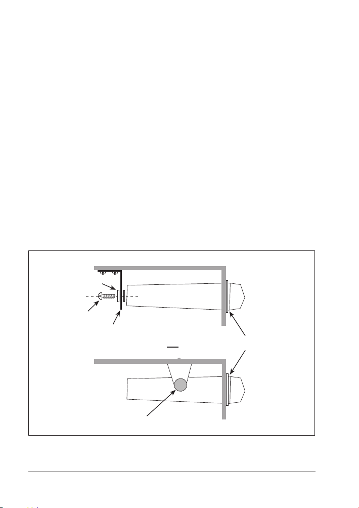
Note: If using the perforated metal support strip, mount it to the rear of the
MST70 as shown in the diagram below.
8. Complete the antenna lead, speaker and power wiring as described later.
Washers
Bolt
Peforated Strip
Escutcheon
Mounting Bracket
Page 6 Owner’s Manual MST70
Page 9

GND
S
E
K
ELECTRICAL WIRING
DC Connections
Caution: The MST70 is designed for vessels with a 12 Volt negative ground
electrical system only!
Referring to the wiring diagram:
1. Connect the Red wire directly to the positive terminal of the vessel’s battery,
or to a point which has +12 Volts available at all times. This lead maintains
the memories within the MST70 and is the main power source for the unit.
2. Connect the Orange wire to the vessel’s +12V supply via an appropriate
isolating switch or circuit breaker. This lead turns the radio ON and OFF.
Alternatively, this wire can be connected directly to the battery’s positive
terminal and the MST70 switched ON and OFF using it’s own controls.
3. Connect the Black lead labelled ‘GROUND’ to the battery’s negative
terminal or to the common negative bus in the electrical system.
External Aux. Switch
(Optional)
Optional Master
Switch
RED
ORANGE
10 AMP
1 AMP
BLACK
Antenna
MST70
Important: Your MST70 is able to maintain it’s memories when it is switched
off by drawing power directly from your battery via the Red lead. Although the
memory backup current is very small (about 7 mA) it may eventually discharge
your battery if left connected indefinitely. The time taken to completely discharge
MST70 Owner’s Manual Page 7
Page 10
your battery could vary depending on it’s Amp-hour rating and condition.
+
–
+
–
+
–
+
–
S
E
K
If you do not run your boat’s motor regularly or your battery is not kept charged
between outings (e.g. Solar or wind charger), we recommend you disconnect
the Red lead each time you secure your boat. This is easily done by connecting
the Red lead via a Master switch which can be switched off after each outing.
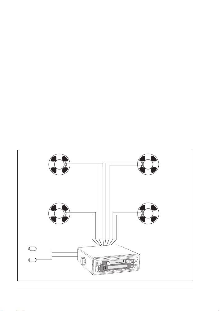
Speaker Connections
When connecting the speakers, observe the correct polarity as shown in the
diagram. Incorrect polarity will result in a reduction of Bass response and stereo
effect. The use of speakers with an impedance of less that 4 Ohms is not
recommended, as they will cause excessive loading of the MST70’s output
circuit.
Caution: The MST70 is a four speaker system that requires 2 separate wires
for each speaker.
• DO NOT connect the negative (-ve) terminals of the speaker wires together
or ground them to any part of the negative electrical Bus.
• DO NOT short the +ve and –ve speaker wires together.
Damage caused by the above will not be covered under warranty.
Connect all four speakers as shown in the diagram. Adjust the Fader control
for the required front/rear balance. If you wish to connect only two speakers,
Left
Front
Left
White
Left Low Level Output
Rear
Red
Grey
Grey/
Black
Green
Green/
Black
Brown
Brown/
Black
Violet
Violet/
Black
Right
Front
Right
Rear
MST70
Right Low Level Output
Page 8 Owner’s Manual MST70
Page 11

connect these to the Rear speaker wires. The remaining speaker wires should
SEL
POWER
LOC
M/S
LOU
MUT
100 WATTS
W.B
AMS
DSP
REL
MAN
SEK
VOL
VOL
MAN
SEK
1 2 3 4 5
6
BND
CONTROL
18
1 2 3 4 5 6 7 8 91110
12
13 14 15 16
17
19 20 21
be insulated to ensure they cannot short circuit together or to ground. If using
only two speakers, adjust the Fader control to the Rear speakers.
Antenna Connections
Connect an AM/FM marine antenna to the antenna socket, which extends from
the rear of the MST70.
FUSE REPLACEMENT
If any of the fuses blow, replace them with the following:
Red lead: 10 Amp, 3AG.
Orange lead: 1 Amp, 3AG.
CONTROLS
1. Panel Release
2. Power
3. Volume Up
4. Eject Cassette
5. Display
6. Cassette Door
MST70 Owner’s Manual Page 9
7. Rewind
8. Fast Forward
9. Display Clock
10. AMS-Auto
Memory Store
11. Local/Distant
12.Mono/Stereo
13. Tune Downwards
14. Function Select
15. Volume Down
16. Tune Upwards
17. Band Selector
18. Station Memories
19. Weather Channels
20. Mute
21. Loudness
Page 12
OPERATION
GENERAL FUNCTIONS
Power ON/OFF
To turn the unit ON, press the POWER button. The unit will resume the mode
that was selected when it was last turned off.
To turn the unit off, press the POWER button again. Note that when the unit is
turned OFF, the clock is displayed.
Controls
The Volume, Bass, Treble, Balance and Fader controls are selected electronically.
The default selection is the Volume control. To select another control, press the
SEL button repeatedly until the name of the control you require is displayed
on the LCD. Each press cycles to the next control in sequence and the display
shows the current setting for that control. If no button is pressed for 3 seconds,
the display returns to normal and the control defaults back to the Volume
control.
• Volume: To adjust the Volume, simply press the VOL or VOL
buttons. 'VOL' will appear on the display along with a number indicating
the current setting. Press VOL to increase the volume level or VOL
to decrease the volume level. A level of 63 on the display indicates
maximum volume.
• Bass: Press the SEL button repeatedly until ‘BAS’ is displayed. Press VOL
to increase the Bass level or VOL to decrease the Bass level. A
level of 0 on the display indicates a flat Bass response.
• Treble: Press the SEL button repeatedly until ‘TRE’ is displayed. Press VOL
to increase the Treble or VOL to decrease the Treble. A level of 0 on
the display indicates a flat Treble response.
• Balance: Press the SEL button repeatedly until ‘BL’ is displayed. Press VOL
to increase the volume in the right speakers. 'BL R' is displayed along
with a number representing the volume level of that channel. Press VOL
to increase the volume in the left speakers ('BL L' is displayed).
To set the Balance to the center position, press VOL or VOL to
reduce the front or rear setting until ‘BL C0’ is displayed, indicating the
centre position.
• Fader: Press the SEL button repeatedly until ‘FA’ is displayed.
Press VOL
the volume in the Rear speakers). ‘FA F’ is displayed along with a number
to show the level of the Rear speaker setting.
Press VOL to fade the sound to the Rear speakers (and reduce the
volume in the front speakers). ‘FA R’ is displayed along with a number to
show the level of the Rear speaker setting.
To set the fader to the centre position, press VOL or VOL to reduce
to fade the sound toward the Front speakers (and reduce
Page 10 Owner’s Manual MST70
Page 13

the front or rear setting until ‘FA C0’ is displayed, indicating the centre
position.
Liquid Crystal Display (LCD)
The LCD indicates the station frequency and the selected band along with
any other selected functions. The display is permanently back lit for low light
viewing.
Loudness LOU
Press the LOU button to increase the bass level at low volume settings. This
feature compensates for the ear's inability to pick up low frequency sounds
when the volume is turned down. When the LOU button is pressed, 'LOUD'
appears on the display.
Mute MUT
Press the MUT button to temporarily silence the sound in the speakers. 'MUTE'
flashes on the display. You can use this feature when talking on your marine
radio. Press MUT again (or the VOL or VOL buttons) to restore the
sound.
RADIO
Band BND
The MST70 has 5 selectable frequency bands labelled FM1, FM2, FM3, MW1
and MW2. Bands FM1 - FM3 are identical and cover the FM band from 87.5
MHz to 107.9 MHz. The MW bands cover the AM frequencies from 530 kHz
to 1710 kHz.
Up to 6 channels in each band can be stored in memory, making 18 FM and
12 AM channels available.
The 3 FM and 2 AM bands allow stations from different areas to be stored and
kept seperate. e.g. Hometown FM stations can be stored using FM1. When
traveling to new areas, new local stations can be located and stored using FM2
or FM3, leaving the hometown stations in FM1 for when you return home.
To change bands, press BND. Each press will advance to the next band i.e.
FM1 - FM2 - FM3 - AM1 - AM2 - etc.
Tuning
Manual Seek ( )
To manually change the frequency in steps, press the TUN or button
repeatedly.
Automatic Seek
To automatically tune the radio to a station, press and hold the TUN or
buttons for more than 1 second. The radio will automatically seek through the
selected band until a station is found, tuning then stops on that station. To tune
MST70 Owner’s Manual Page 11
Page 14

to the next station, press and hold the TUN or buttons again.
Manual Station Preset
To manually store stations in the station memories:
1. Select the required station frequency using the TUN or buttons.
2. When the station is tuned, press and hold the required station preset
number 1 - 6 for more than 2 seconds. The selected station will be stored
in that preset memory and the preset number will be displayed.
To recall station memories, briefly press the required station preset number 1 - 6.
Auto Memory Store AMS
Use the Auto Memory Store AMS function to automatically locate stations
and store them in memory. In FM mode, stations are stored in order of signal
strength with the strongest signals being stored first. In AM mode, stations are
stored in the sequence in which they are found.
To automatically store stations in memory, press and hold the AMS button
for more than 1 second. 'ATP' will be displayed when Auto Memory Store is
functioning.
• In FM mode, the radio will begin tuning upwards through the entire selected
band (FM1, FM2 or FM3), starting at the currently selected frequency and
returning to that frequency when finished. The memories for that band will
then contain the six strongest FM stations in your area.
• In the AM mode the radio will begin tuning upwards (from the currently
selected frequency) and will store the first six stations found. Tuning will
then stop.
Note: If the AM stations you wish to store were not included because
the memories were filled up by other unwanted stations, select a frequency to
start from that which is just below the stations you wish to store (using the TUN
or buttons, then press the AMS button. Stations will be then located and
stored starting from the selected frequency. Alternatively, if the memories were
filled by weak unwanted stations, select the Local mode (by pressing the LOC
button) so that only the stronger local stations are located and stored - see
Local/Distant operation described below.
Mono/Stereo M/S
The M/S button can be used to select either Mono or Stereo reception when
in FM mode.
• Mono: Selecting Mono improves reception when FM signals are weak or
noisy, by disabling stereo detection. When selected, there is no indication
on the display. Note: MONO selection is only available on the FM, FM2 or
FM3 bands.
• Stereo: Select stereo for normal stereo listening on the FM radio bands. When
stereo is selected and a stereo signal is being received, ST is displayed.
Page 12 Owner’s Manual MST70
Page 15

Local/Distant LOC
Press the LOC button to reduce the radio's sensitivity to weaker, distant
signals. 'LOC' is displayed. This is particularly useful when seeking or autostoring local stations as it reduces the weaker signals so that only the stronger
local signals are found and stored.
To intentionally receive weak or distant signals, press the LOC button again
to return to Distant mode.
Clock DSP
To display the clock on the LCD, press the DSP (display) button. To return to
the previous mode, press the DSP button again.
To set the clock:
1. Press the DSP button to display the clock.
2. Now press and hold the DPS button while pressing the button to adjust
the hours or the button to adjust the minutes.
RESET
Your MST70's functions are controlled by a microprocessor. If after installation,
you find that some of the functions do not appear to work correctly, you can
reset the microprocessor to restore the radio to its default settings. Note that
after the reset, you will need to reprogram your station memories.
The reset button is located beneath the removable front panel. To reset the
radio:
1. Press the release button to remove the front panel (see 'Detachable Front
Panel' on page 3).
2. Locate the reset switch using the diagram below.
3. Press the switch using a ball point pen or similar.
Reset Switch
MST70 Owner’s Manual Page 13
Page 16

CASSETTE PLAYER
Insert a cassette tape into the cassette door with the side you wish to play
facing upwards and the exposed tape facing to the right. TAPE will appear
on the LCD display along with an arrow indicating the direction the cassette
is playing.
To fastforward or rewind the cassette, press the fastforward >> or rewind
<< buttons. Press >> for fastforward and << for rewind regardless of which
direction the tape is playing. To stop fastforward or rewind, press the opposite
button. i.e. press << to cancel >> etc.
When the tape reaches the end, the unit will automatically reverse the play
direction and play the other side of the tape.
To change the play direction manually, press << and >> simultaneously. The
direction indicator on the display will change to indicate the new direction.
To stop the tape and eject the cassette, press the eject button ^.
Page 14 Owner’s Manual MST70
Page 17

SPECIFICATIONS
General
DC Supply Input...................................................................................... 11 - 16V
Current:
Standby ..................................................................................................7 mA
Typical ................................................................................................700 mA
Maximum ...............................................................................................2.5 A
Antenna Input Static & RF Protection................................. Back to Back Diodes
Dimentions (approx)............................................7.7(W) x 3.15(H) x 9.3(D) inches
Maximum Height with Bracket.............................................................4.7 inches
FM Radio
Frequency Range......................................................................87.5 - 107.9 MHz
Intermediate Frequency.........................................................................10.7 MHz
Sensitivity (30 dB S/N).............................................................................18 dBµV
Selectivity (±200 kHz).................................................................................-30 dB
Station Memories....................................................................18, FM1/FM2/FM3
AM Radio
Frequency Range......................................................................... 530 - 1710 kHz
Intermediate Frequency...........................................................................450 kHz
Sensitivity (30 dB S/N).............................................................................20 dBµV
Selectivity (±9 kHz)......................................................................................30 dB
Station Memories..........................................................................12 MW1, MW2
Audio Amplifier
Audio Output (10% Dist.)............................60 Watts Total, 15 Watts RMS x 4CH
Output Impedance......................................................................4 ohms/channel
Bass Control................................................................................±8 dB @ 100 Hz
Treble Control..............................................................................±8 dB @ 10 kHz
Stereo Cassette Deck
Deck type................................................................................4 track, 2 program
Cross Talk....................................................................................................40 dB
Wow & Flutter..............................................................................................0.35%
NOAA Weather Channels
Sensitivity (12 dB SINAD)............................................................................0.7 µV
Frequency Range ...............................................................CH:1 162.550 MHz
CH:2 162.400 MHz
CH:3 162.475 MHz
CH:4 162.425 MHz
CH:5 162.450 MHz
CH:6 162.500 MHz
CH:7 162.525 MHz
CH:8 161.650 MHz
CH:9 161.775 MHz
CH:10 163.275 MHz
MST70 Owner’s Manual Page 15
Page 18

ACCESSORIES
AS101....................................................................6-inch Flush-Mount Speakers
(available in black or white)
AS201....................................................................7-inch Flush-Mount Speakers
(white only)
CMB60........................................................................................ Flush-Mount Kit
(white only)
CMB60
AS101
Page 16 Owner’s Manual MST70
AS201
Page 19

STANDARD HORIZON MARINE DIVISION OF YAESU U.S.A. warrants to the original
purchase r only that each new Marine Product manufactured and/or supplied by
STANDARD HORIZON will be free from defects in materials and workmanship under
conditions of normal use and service for a period of one (1) year from the date of
delivery to the Purchaser. STANDARD HORIZON’s liability under this warranty shall
be limited to the repair or re placement of the defective product, at STANDAR D
HORIZON’s option, under no circumstances shall STANDARD HORIZON be made
liable for consequential, incidental, or other damages arising out of or in any way
connected with a failure of the product to perform as set forth herein.
In the event of a defect, malfunction, or failure of the product to conform to specifications
during the one-year warranty period, STANDARD HORIZON will repair or replace, at its
option and without charge to the Purchaser, the product which upon examination by
STANDARD HORIZON shall appear to be defective or not up to factory specifications.
To obtain warranty service, the defective product must be returned to STANDARD
HORIZON together with proof of the date of purchase. The Purchaser must pay any
transportation expenses in returning the product to STANDARD HORIZON. STANDARD
HORIZON will examine the product and respond to the Purchaser within approximately
four (4) weeks from the date of receipt of the product claimed to be defective.
This limited warranty does not extend to any Product which has been subjected to
misuse, neglect, accident, improper installation, or subject to use in violation of the
maintenance of operating instructions, if any, furnished by STANDARD HORIZON, nor
does this warranty extend to products on which the serial number has been removed,
defaced, or changed. STANDARD HORIZON reserves the right to make changes or
improvements to its products without notice during subsequent production without
incurr ing the oblig ation to install such changes or improvement s on pre viously
manufactured or sold products.
To receive warranty service, the Purchaser must deliver the product, transportation
and insurance prepaid, to STANDARD HORIZON Marine Division of Yaesu U.S.A.,
115 North Wright Brothers Dr. Salt Lake City, Utah 84116-2838. Include proof of
purchase indicating model, serial number and date of purchase. STANDARD HORIZON
will return the Product to the Purchaser freight prepaid.
Some states do not allow limitations on the duration of the warranty or exclusions or
limitations of incidental or consequential damages so these limitations or exclusions
may not apply to you. This warranty gives you specific legal rights, which may vary
from state to state.
Lifetime Flat Rate Service Program: For the original Purchaser only, for the lifetime of
the unit, STANDARD HORIZON will repair the unit to original specifications.
Note: The flat rate amount is payable by the Purchaser only if STANDARD HORIZON
determines that a repair is needed. After the repair, a 90-day warranty will be in effect
from the date of return of the unit to the Purchaser.
Owner’s Records
Model Serial number
Purchase date Dealer
MST70 Owner’s Manual Page 17
Page 20

Marine Division of Yaesu U.S.A.
17210 EDWARDS ROAD,
CERRITOS, CA 90703
Telephone 562/404-2700
STANDARD HORIZON 1999
ALL RIGHTS RESERVED
PRINTED IN CHINA
January 2000
 Loading...