

Page 1
MST65
Deluxe AM/FM
Stereo System
Owner's Manual
Page 2

TABLE OF CONTENTS
FEATURES..........................................................................................1
ACCESSORIES...................................................................................1
REPLACEMENT PARTS....................................................................1
LISTENING TO FM ON YOUR BOAT................................................2
CASSETTE CARE AND MAINTENANCE..........................................2
INSTALLATION.................................................................................. 3
MOUNTING.........................................................................................3
Upright or Overhead Mounting......................................................3
Flush Mounting..............................................................................4
Installation using the Supplied Escutcheon Panel.........................5
ELECTRICAL CONNECTION...............................................................6
FUSE REPLACEMENT........................................................................6
SPEAKER INSTALLATION.................................................................. 7
CONTROLS........................................................................................ 8
Volume ON/OFF.............................................................................8
Balance..........................................................................................8
Fader..............................................................................................8
Bass and Treble.............................................................................9
Loudness (LD)................................................................................9
Liquid Crystal Display (LCD).......................................................... 9
Band (BND)....................................................................................9
Tuning............................................................................................9
Manual Station Preset..................................................................10
Auto Memory Store (AS)..............................................................10
Preset Scan (PS)..........................................................................10
Clock (CLK)..................................................................................11
CASSETTE PLAYER..........................................................................11
Noise Reduction (NR).................................................................. 11
Metal Oxide Tapes (MT)...............................................................11
SPECIFICATIONS............................................................................ 12
GENERAL..........................................................................................12
FM RADIO......................................................................................... 12
AM RADIO.........................................................................................12
AUDIO AMPLIFIER............................................................................12
STEREO CASSETTE DECK...............................................................12
TROUBLESHOOTING......................................................................13
MAINTENANCE................................................................................13
LIMITED WARRANTY......................................................................14
Page 3

MST65 Owner’s Manual Page 1
FEATURES
●
Sealed water resistant marine housing using corrosion proof materials.
●
Large easy-to-read LCD display of station memories, frequency, selected
function and time.
●
Automatic tune and store feature to locate and memorize stations.
●
Special "night vision" orange back lighting of the display and all controls.
●
Extended station memories - 18 FM and 6 AM.
●
Built-in protection against damage from static or high power radio
transmissions.
●
Provisions for four speakers with Fader control.
●
60 watts, total power.
●
Separate Base and Treble controls.
●
Built-in clock automatically displays the time while the cassette is playing
or the unit is switched off, and at a press of a key when using the radio.
●
Automatic Stereo/Mono switching and soft muting control.
●
Metal tape and tape noise reduction controls.
●
Reverse polarity protection of the DC input.
ACCESSORIES
AS101....................................................................7-inch Flush Mount Speakers
(available in black or white)
AS301.......................................... Bookshelf-Style High Fidelity Audio Speakers
(available in black or white)
CMB60.........................................................................................Flush Mount Kit
REPLACEMENT PARTS
PART SCC PART NUMBER
Dust Cover........................................................................................053002027A
Flush Mount Escutcheon..................................................................063002002A
Mounting Bracket.............................................................................160004023A
Mounting Bracket Knobs..................................................................154011017A
Power Wire Harness.........................................................................156007001A
Rear Case Assembly.......................................................................M32649001A
Speaker Wire Harness......................................................................156008001A
Page 4

Page 2 Owner’s Manual MST65
LISTENING TO FM ON YOUR BOAT
The majority of FM broadcasts are music programs. Compared with AM
signals, FM signals have a wider dynamic range, are relatively immune to noise
and provide virtually distortion-free music reproduction. However, because of
the nature of FM signals and the fact that FM stations are usually positioned
for shore-based reception, receiving them in a moving boat may be
accompanied by problems.
●
FM programs are broadcast for local reception and cannot be heard
satisfactorily at distant locations. To enjoy FM programs at their best, it is
important that you tune to a station that is broadcasting in your locality.
●
FM signals can reflect from solid objects such as buildings or hills. If these
reflected signals are received along with signals arriving directly from the
transmitter, they may mix together to produce what is known as "multipath
distortion". This distortion is heard as noise. Often moving as little as 3 feet
from your position will correct this problem.
●
FM signals travel in straight lines. Because the signals are reflected from
or absorbed by large solid objects, a signal shadow may be present
behind the object which may result in poor reception in that area.
CASSETTE CARE AND MAINTENANCE
1. Tapes no longer than C-90 (90 minutes playing time) are recommended.
Avoid using C-120 tapes because they are extremely thin and may jam
your cassette player mechanism.
2. The most common cause of poor sound reproduction is a contaminated
tape head. Signs of contamination include low volume on one or both
channels and failure to reproduce high frequency notes. The head can be
cleaned using a cotton applicator soaked in alcohol. If the cassette unit is
used for more than one hour each day, the head should be cleaned once
or twice a month.
3. To extend the life of your cassettes, keep them away from:
●
areas exposed to the sun
●
top of instrument panels
●
the engine
●
areas exposed to heat and moisture
●
magnetic fields (such as speakers)
4. Replace tapes in their plastic cases when not in use.
5. Do not oil revolving parts.
Page 5
MST65 Owner’s Manual Page 3
INSTALLATION
MOUNTING
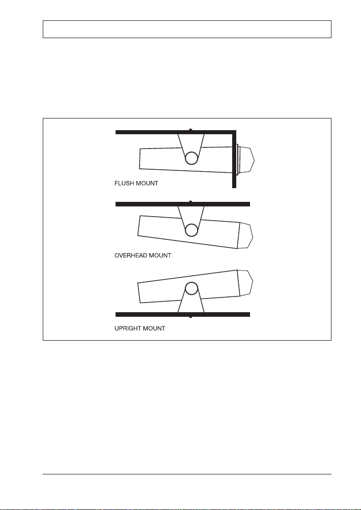
The MST65 is designed to be mounted in several different ways so that it can
be installed in the most convenient position. Although the MST65 is water
resistant when the front cover is closed, care should be taken to locate it
where it will not be subjected to spray or rain. Figure 1 shows the various
methods of mounting available.
Figure 1. Upright or Overhead Mounting
Upright or Overhead Mounting
1. Attach the two gimbal knobs and self-adhesive rubber washers to the
MST65 and slide the unit into the mounting bracket. Ensure the rubber
washers are between the bracket and the radio. Tighten the knobs firmly.
2. Temporarily position the MST65 in the desired location, tilting the radio in
the bracket to ensure you are able to get the required adjustments for
viewing angle etc.
2808
Page 6
3. Roughly mark the location of the bracket edges, then separate the radio
from the bracket and reposition the bracket to mark the mounting hole
positions. A range of mounting holes is provided to suit most installations.
4. Screw or bolt the bracket into position. The mounting method will depend
on the material to which the bracket is being attached.
5. Slide the MST65 back into the bracket slots and adjust to the required
position before tightening the gimbal knobs.
6. Connect the antenna lead and electrical wiring as described later.
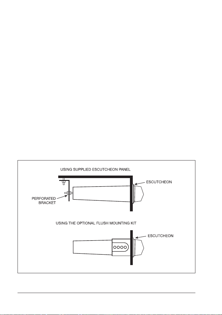
Flush Mounting
The MST65 can be neatly flush mounted into a panel or bulkhead so that just
the controls and the protective cover are visible. There are two flush mounting
options available. The best option for you will depend on your particular
situation.
●
If the space behind the bulkhead or panel you have selected has a suitable
support shelf and the area is fully accessible, you can use the supplied
escutcheon panel as described later.
●
If the space behind the bulkhead or panel is largely inaccessible or there is
no additional support shelf, we recommend you use the optional flush
mounting kit (available as an accessory). This kit is more robust, is fully self
supporting and allows the MST65 to be installed from the front.
Figure 2. Flush Mounting
Page 4 Owner’s Manual MST65
2809
Page 7

Installation using the Supplied Escutcheon Panel
1. Select a suitable location on a panel or bulkhead.
2. Examine behind the bulkhead to determine the best method of support for
the radio. Examples of internal support methods are shown in Figure 2.
3. Place the escutcheon on the bulkhead or panel in the required position and
pencil around the outside edge of the escutcheon slot wall (see Figure 3).
4. Remove the escutcheon and measure your marks. They should measure
approximately 7 7/8 inches wide by 2 3/4 inches high. If not, check Figure
3 to ensure you measured the correct edge.
5. If your measurements are correct, carefully cut the slot around the marked
lines, ensuring that you maintain the curves in each corner.
6. Mark and drill four 1/8-inch holes in the bulkhead to accept the
escutcheon locating pins at each corner of the escutcheon.
7. Trial fit the escutcheon to ensure it fits securely against the panel. If all fits
well, put a small dab of glue on each locating pin and press the
escutcheon firmly into place. Temporarily hold in place with tape if
necessary.
8. With the escutcheon in place, slide the MST65 through the slot from the
front and push it almost as far as it will go. The radio should not be pushed
all the way in, to ensure there is adequate clearance for the front cover to
hang in the open position. Open the cover if necessary to check for the
correct clearance.
9. Holding everything in position, mark the location of the internal support
bracket(s). Drill the required holes and fit the bracket(s) as required to
firmly hold the MST65 in place.
10. Connect the antenna lead and electrical wiring as described later.
NOTE: Installation Instructions for the optional Flush Mount Kit are supplied
with the kit.
Figure 3. Escutcheon Dimensions
MST65 Owner’s Manual Page 5
2810
Page 8

ELECTRICAL CONNECTION
FOR NEGATIVE GROUND ELECTRICAL SYSTEMS ONLY. See Figure 4.
The MST65 is intended for use in vessels with a 12 volt negative ground
electrical system. The Positive RED fused lead must be connected to the
positive (+) side of the electrical system and the Negative BLACK lead must be
connected to the ground negative (-) side. Reversal of these connections will
cause the fuse to blow and may seriously damage the unit, voiding the
warranty.
On smaller vessels, the negative BLACK lead can be connected directly to the
negative (-) terminal of the battery. The positive RED lead can go directly to the
battery positive (+) terminal, or if more convenient, to an accessory post on the
ignition switch.
On larger vessels with a switchboard, the negative lead should go to the
common negative bus and the positive lead to the switched and fused radio
(or spare) power circuit.
The orange fused lead is used to maintain the memories inside the radio and
must be connected to a continuous +12 Volt point such as the positive (+)
terminal of the battery.
NOTE: It is possible to use the MST65 on vessels with a 12 volt positive
ground electrical system, but special precautions are required when installing
the stereo system antenna and any accessories. If in doubt, consult a qualified
marine electronics technician.
FUSE REPLACEMENT
If any of the fuses blow, replace them as follows:
RED supply lead fuse: 7 Amp 3 AG type (1 3/16 inches)
ORANGE memory lead fuse: 1 Amp 3AG type (1 3/16 inches)
Figure 4. Electrical Connections
Page 6 Owner’s Manual MST65
2811
-
+
1
Page 9

SPEAKER INSTALLATION
To obtain the best possible sound, flush-mount speakers should be mounted
in a bulkhead or panel to provide adequate isolation between the front and
rear of the speaker. A baffle area of approximately 2ft x 2ft is desirable when
bulkhead mounting. If mounting on a shelf or panel, the speaker can be
enclosed in a box, preferably with a volume area of 1 cubic foot.
Speakers which are fully enclosed in their own speaker boxes and incorporate
a gimbal mounting bracket can be mounted in any convenient location.
Although these speakers have water resistant cones, they should be mounted
in a sheltered position away from direct spray.
See Figure 5 for speaker connections.
WARNING
●
Do not allow the speaker leads (even the common lead) to come into
contact with grounded metal on the vessel or the negative (-) supply. If any
speaker lead is connected to chassis ground, the amplifier in the MST65
will be damaged.
●
Do not allow the speaker leads to "short" together as this will also cause
damage to the MST65 amplifier. Damage caused by the above may not be
covered by warranty.
Figure 5. Speaker Installation
MST65 Owner’s Manual Page 7
1
-
+
2812
Page 10

CONTROLS
Refer to Figure 6 for location of controls.
Figure 6. Controls
Volume ON/OFF
Rotate the Volume knob clockwise to turn the unit on. Rotate the control
further to increase the volume.
Balance
Grasp the Volume knob and pull it outwards while rotating it left or right to
adjust the speaker left-right balance. The center balance point is indented for
easy location.
Fader
Rotate the concentric Fader knob to adjust the balance between the front and
rear speakers. Rotate clockwise to increase the front speaker volume and
counterclockwise to increase the rear speaker volume.
Page 8 Owner’s Manual MST65
2813
Page 11

Bass and Treble
Slide the Bass or Treble controls to the right to increase the Bass or Treble
response. The center "flat response" position is indented for easy location.
Loudness (LD)
The LD key is used to increase the low frequency response at low to medium
volume levels. This provides compensation for the human ear which does not
respond well to low frequencies at lower volumes. When selected, "LD" is
displayed.
Liquid Crystal Display (LCD)
The LCD indicates the station frequency and the selected band along with any
other selected functions. The display is permanently backlighted for low light
viewing.
Band (BND)
The MST65 has 4 selectable frequency bands labeled FM1, FM2, FM3 and
MW. Bands FM1 - FM3 are identical and cover the FM band from 87.5 MHz to
108 MHz. The MW band covers the AM frequencies from 531 kHz to 1620
kHz. The separate FM bands allow stations from different areas to be stored
and kept separate. Up to 6 channels in each band can be stored in memory,
making 18 FM and 6 AM channels available.
e.g. Hometown FM stations can be stored using FM1. When traveling to new
areas, new local stations can be located and stored using FM2 or FM3, leaving
the hometown stations in FM1 for when you return home.
To change bands, press BND. Each press will advance to the next band i.e.
FM1 - FM2 - FM3 - MW - FM1 etc.
Tuning
Manual Tuning (< >)
To manually tune the radio, press the < or > keys. Press > to tune to a higher
frequency and < to tune to a lower frequency. Release the key when the
desired frequency is displayed. The sound is muted while tuning.
Seek Tuning (>>)
To automatically tune the radio to a station, press the >> Seek key. The radio
will automatically seek upwards through the selected band until a station is
found. Tuning then stops on that station. To tune to another station, press the
>> key again.
MST65 Owner’s Manual Page 9
Page 12

Manual Station Preset
To manually store stations in the station memories:
1. Select the required station frequency using either the < or > manual tune
keys or the >> seek key.
2. Press the ME key. "ME" will flash on the display for 5 seconds. During this
time, press the required station preset number 1 - 6. The selected station
will be stored in that preset memory and the preset number will be
displayed
To recall station memories, press the required station preset number 1- 6.
Auto Memory Store (AS)
Use the Auto Memory Store AS function to automatically locate and store
stations in memory. In FM mode (bands FM1, FM2 and FM3), stations are
stored in order of signal strength with the strongest signals being stored first.
In AM mode (MW band), stations are stored in the sequence in which they are
found.
To automatically store stations in memory, press the AS key. "8" will flash in
the top right corner of the LCD while the Auto Memory Store is functioning.
In FM mode, the radio will begin scanning upwards through the entire selected
band (FM1, FM2 or FM3), starting at the currently selected frequency and
returning to that frequency when finished. The memories for that band will then
contain the six strongest FM stations in your area.
In the AM mode, the radio will begin scanning upwards (from the currently
selected frequency) and will store the first six stations found. Scanning will
then stop.
Note: If the AM stations you wish to store were not included because the
memories were filled up too soon by other unwanted stations, select a
frequency to start from that is just below the stations you wish to store (using
the < > manual tune keys or the >> seek key), then press the AS key.
Stations will be then located and stored starting from the selected frequency.
Preset Scan (PS)
The Preset Scan function automatically steps through all preset stations in
sequence, pausing to play each station for 5 seconds.
To start the Preset Scan, press the PS key. The radio will begin stepping
through and playing each station preset in memory and the current station
memory number will flash in the top right of the display.
Note: In FM mode, the preset scan will step through all 18 channels of the
three FM bands (FM1, FM2 and FM3).
Page 10 Owner’s Manual MST65
Page 13

To cancel the Preset Scan and remain on the current station, press the PS key
again.
Clock (CLK)
To display the clock on the LCD, press the CLK key. The display will return to
normal after 5 seconds.
To set the clock:
1. Press CLK to display the clock.
2. Press and hold ME while pressing 1 to adjust the hours.
3. Press and hold ME while pressing 2 to adjust the minutes.
Note: When playing cassettes, the clock is displayed automatically. During this
time the clock can be set without the need to press the CLK key.
CASSETTE PLAYER
Insert a cassette tape into the cassette door with the side you wish to play
facing upwards and the exposed tape facing to the right. The LCD will indicate
the direction the cassette is playing and the clock will be displayed.
To fastforward or rewind the cassette, press and lock the fastforward or
rewind keys. Press for fastforward and for rewind regardless of
which direction the tape is playing. To stop fastforward or rewind, press the
opposite key. i.e. press to cancel , etc.
When the tape reaches the end, the unit will automatically reverse the play
direction and play the other side of the tape.
To change the play direction manually, press and simultaneously.
The direction indicator on the display will change to indicate the new direction.
To stop the tape and eject the cassette, press the eject key .
Noise Reduction (NR)
To reduce any annoying background hiss when playing tapes, press the NR
noise reduction key. "NR" will be displayed.
Metal Oxide Tapes (MT)
Metal oxide tapes are often used as an alternative to standard tapes because
of their better frequency response and lower background hiss. The MST65 is
fitted with a metal tape key MT to ensure the best performance is obtained
when using these tapes. When MT is pressed, "MTL" will be displayed.
MST65 Owner’s Manual Page 11
Page 14

SPECIFICATIONS
General
DC Supply Input.....................................................................................11 - 16 V
Current:
Standby..................................................................................................5 mA
Typical................................................................................................700 mA
Maximum................................................................................................2.5 A
Antenna Input Static & RF Protection.................................Back to Back Diodes
Dimensions (approx.)..........................................7.7(W) x 3.15(H) x 9.3(D) inches
Maximum Height with bracket..............................................................4.7 inches
FM Radio
Frequency Range......................................................................87.5 - 108.1 MHz
Intermediate Frequency.........................................................................10.7 MHz
Sensitivity (30dB S/N)...................................................................................4 mV
Selectivity (± 200 kHz)............................................................................... -30 dB
Station Memories....................................................................18, FM1/FM2/FM3
AM Radio
Frequency Range.........................................................................530 - 1620 kHz
Intermediate Frequency...........................................................................450 kHz
Sensitivity (20 dB S/N).................................................................................30 µV
Selectivity (±9 kHz)......................................................................................30 dB
Station Memories....................................................................................... 6, MW
Audio Amplifier
Audio Output (10% Dist.).......................... 60 Watts Total, 15 Watts RMS x 4CH
Output Impedance......................................................................4 ohms/channel
Bass Control............................................................................... ±8 dB @ 100 Hz
Treble Control............................................................................. ±8 dB @ 10 kHz
Stereo Cassette Deck
Deck type................................................................................4 track, 2 program
Cross Talk................................................................................................... 40 dB
Wow & Flutter.............................................................................................0.35%
Page 12 Owner’s Manual MST65
Page 15

TROUBLESHOOTING
The following checks will assist you in solving most of the problems you are
likely to encounter after installing your MST65. Should any problem persist
after you have tried these ideas, consult your dealer.
MAINTENANCE
Your stereo is designed for years of trouble-free operation assuming proper
installation and care of the unit are provided. Following the installation and
operation guidelines in this manual should ensure optimum performance of the
stereo.
In the unlikely event that the stereo shall fail to perform or shall need servicing,
please contact the following:
Factory Service Facility
SCC-Standard Communications Corp.
115 North Wright Brothers Drive
Salt Lake City, Utah 84116-2838
Telephone Number: 1-800-366-4566
FAX Number: 1-801-359-4122
MST65 Owner’s Manual Page 13
CAUSE
The boat's ignition is not turned
on or is not in the accessory
position.
The Fuse has blown.
The Volume or Fader controls
are not set correctly.
The speakers are not
connected correctly.
The antenna is not connected.
The antenna cable is not
connected correctly.
The station is not properly
tuned in.
The station you are tuned to
has a very weak signal.
Loose positive 12V
connections or blown fuse.
SYMPTOM
No Power.
No Sound.
The radio does not work.
The radio reception is noisy.
Blank display.
SOLUTION
Turn the ignition key to the
ACC or ON position.
Replace the fuse with one of
the same rating.
Adjust the Volume and Fader
controls.
Recheck the speaker wiring.
Ensure no speaker wires are
shorting together or to ground.
Connect the antenna to the
antenna socket.
Check the antenna connection.
Retune the radio.
Select a stronger station.
Check red and orange wires
and 2 fuses.
Page 16

LIMITED WARRANTY
STANDARD COMMUNICATIONS CORP. ("SCC") warrants, to the original purchaser only, each new
Marine Communications Product ("Product") manufactured and/or supplied by SCC against defects in
material and workmanship under normal use and service for a period of time from the date of purchase
as follows:
MST65 Marine AM/FM Stereo System - 1 year
To receive warranty service, the purchaser must deliver the Product, transportation and insurance
prepaid, to SCC Standard Communications Corp.,115 North Wright Brothers Drive, Salt Lake City, Utah
84116-2838. Include proof of purchase indicating model, serial number, and date of purchase. SCC will
return the Product to the purchaser freight prepaid. Products purchased prior to January 1, 1991 will
bear the SCC warranty terms in effect prior to that date.
In the event of a defect, malfunction or failure of a Product during the warranty period, SCC's liability for
any breach of contract or any breach of express or implied warranties in connection with the sale of
Products shall be limited solely to repair or replacement, at its option, of the Product or part(s) therein
which, upon examination by SCC, shall appear to be defective or not up to factory specifications. SCC
may, at its option, repair or replace parts of subassemblies with new or reconditioned parts and
subassemblies. Parts thus repaired or replaced are warranted for the balance of the original applicable
warranty.
SCC will not warrant installation, maintenance or service of the Products. In all instances, SCC's liability
for damages shall not exceed in purchase price of the defective Product. This warranty only extends to
Products sold within the 50 States of the United States of America and District of Columbia.
SCC will pay all labor and replacement parts charges incurred in providing the warranty service except
where purchaser abuse or other qualifying exceptions exist. The purchaser must pay any transportation
expenses incurred in returning the Product to SCC for service.
This limited warranty does not extend to any Product which has been subjected to misuse, neglect,
accident, incorrect wiring by anyone other than SCC, improper installation, or subjected to use in
violation of instructions furnished by SCC, nor does this warranty extend to Products on which the serial
number has been removed, defaced, or changed. SCC cannot be responsible in any way for ancillary
equipment not furnished by SCC which is attached to or used in connection with SCC's Products, or the
operation of the Product with any ancillary equipment and all such equipment is expressly excluded from
this warranty. SCC disclaims liability for range, coverage, or operation of the Product and ancillary
equipment as a whole under this warranty. SCC reserves the right to make changes or improvements in
Products, during subsequent production, without incurring the obligation to install such changes or
improvements on previously manufactured Products.
The implied warranties which the law imposes on the sale of this Product are expressly LIMITED in
duration, to the time period specified above. SCC shall not be liable under any circumstances for
consequential damages resulting from the use and operation of this Product, or from the breach of this
LIMITED WARRANTY, any implied warranties, or any contract with SCC. IN CONNECTION WITH THE
SALE OF ITS PRODUCTS, SCC MAKES NO WARRANTIES, EXPRESS OR IMPLIED AS TO THE
MERCHANTABILITY OR FITNESS FOR A PARTICULAR PURPOSE, OR OTHERWISE, EXCEPT AS
EXPRESSLY SET FORTH HEREIN.
Some states do not allow the exclusion or limitation of incidental or consequential damages, or limitation
on how long an implied warranty lasts, so the above limitations or exclusions may not apply. This
warranty gives specific legal rights, and there may be other rights which may vary from state to state.
ONLY PRODUCTS SOLD ON OR AFTER JANUARY 1, 1991 WILL BE COVERED UNDER THE TERMS
OF THIS LIMITED WARRANTY.
Page 14 Owner’s Manual MST65
Page 17

WARRANTY INFORMATION CARD
Model Serial Number Purchase Date
Please give us your opinion about our product
1. What is your overall evaluation of the product?
❏
Excellent ❏Good ❏ Poor
2. What do you like most about it?
3. What do you like least about it?
4. Does the Owner’s Manual provide adequate information to install and operate the equipment?
❏
Yes ❏No Comments
About your boat: About your purchase decision:
5. Type of boat: 9. Where was the equipment purchased?
❏
Sail
❏
Boat/Motor Dealer
❏
Power
❏
Marine Electronics Dealer
❏
Commercial
❏
Mail Order
❏
Other
6. Length of boat: ft
10. Why did you choose Standard Horizon?
7. Where do you use your boat?
❏
Features
❏
Salt Water
❏
Price
❏
Fresh Water
❏
Recommendation of Dealer
❏
Other
8. Equipment on board
Now Own Plan to Buy 11. If you hadn’t chosen Standard, what was
❏ ❏
Autopilot your next choice? (indicate brand):
❏ ❏
Desalinator
❏ ❏
Digital Depth Sounder
❏ ❏
GPS 12. How did you learn about Standard Horizon?
❏ ❏
EPIRB
❏
Advertisement
❏ ❏
Loran
❏
Dealer
❏ ❏
Radar
❏
Friend
❏ ❏
Single Sideband
❏
Magazine article
❏ ❏
VHF Radio - Fixed
❏
Previously owned
❏ ❏
VHF Radio - Handheld
❏
Other
❏ ❏
Video Fishfinder
❏ ❏
Windspeed/Point 13. What boating magazines do you read?
❏ ❏
Speed Log
✂
Page 18

Standard Communications Corp.
Attn: Advertising Department
P.O. Box 92151
Los Angeles, CA 90009-2151
PLACE
STAMP
HERE
Owner’s name and address (please type or print)
Page 19

WARRANTY INFORMATION CARD INSTRUCTIONS
Please complete the Warranty Information Card on the previous page, detach
it and mail it to SCC. Then complete the Owner’s Record below for your
records. Should you ever return the equipment to your SCC Dealer or SCC for
in-warranty repair, the Owner’s record, or other proof of purchase, must be
included with the unit to provide warranty information.
THANK YOU for buying Standard Communications products! We are
confident your new radio will serve your needs for many years!
OWNER’S RECORD
Model Serial Number
Purchase Date Dealer
Owner’s Name and Address
IMPORTANT
Be sure to put this same name and address on the reverse side of this Warranty Information Card
before you mail it to SCC!
Page 20

Standard Communications Corp.
P.O. Box 92151
Los Angeles, CA 90009-2151
Telephone 310/532-5300
© Standard Communications Corp. 1997
All Rights Reserved
Printed in Australia
September 1997 M32685102A
 Loading...