

Page 1
MLS-300i
Intercom Speaker
The MLS-300i is a high performance intercom speaker with Push To Alert button (PTA) designed to operate with the Standard
Horizon VLH-3000 Loud Hailer.
INSTALLATION
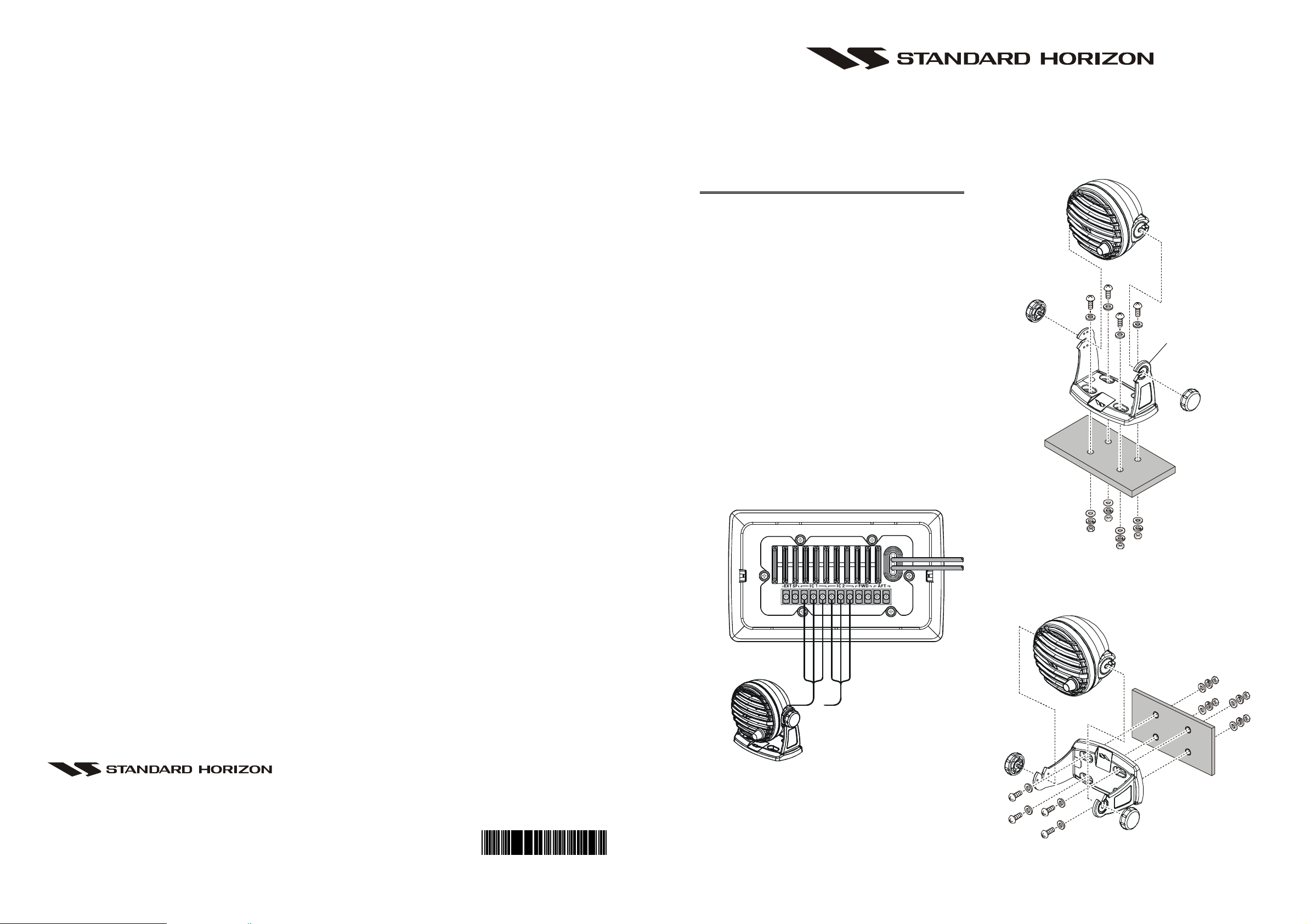
1) MOUNTING BRACKET INSTALLATION
1. Remove the MLS-300i from the bracket by removing the
two Mounting Bracket Knobs.
2. Choose a place to mount the MLS-300i.
3. Use the bracket as a template to mark the locations of the
mounting holes.
4. Use a 5.2-mm (17/64”) bit to drill the holes, and secure
the bracket with the supplied screws, spring washers, flat
washers, and nuts (Figure 1 & 2).
5. Insert the MLS-300i into the bracket with the Mounting
Bracket Knobs which were removed in step 1.
6. Set the MLS-300i to the preferred angle, then tighten the
Mounting Bracket Knobs to fasten the MLS-300i to the
bracket.
7. Route and secure the connection cable from the MLS-300i
to the VLH-3000 Loud Hailer. Connect the WHITE wire
of the connection cable to the “positive (+) intercom
speaker output,” the shield of the connection cable to the
“negative (–) intercom speaker,” and the YELLOW wire
of the connection cable to the “push to alert” terminal (Figure 3).
You may reverse
the position of the
bracket.
Marine Division of VERTEX STANDARD
US Headquarters
10900 Walker Street, Cypress, CA 90630, U.S.A.
www.standardhorizon.com
EAE31X200
YELLOW
WHITE
BLACK
BLACK
or
Figure 3
Figure 1 (Desktop Mount)
YELLOW
WHITE
Figure 2 (Wall Mount)
Page 2
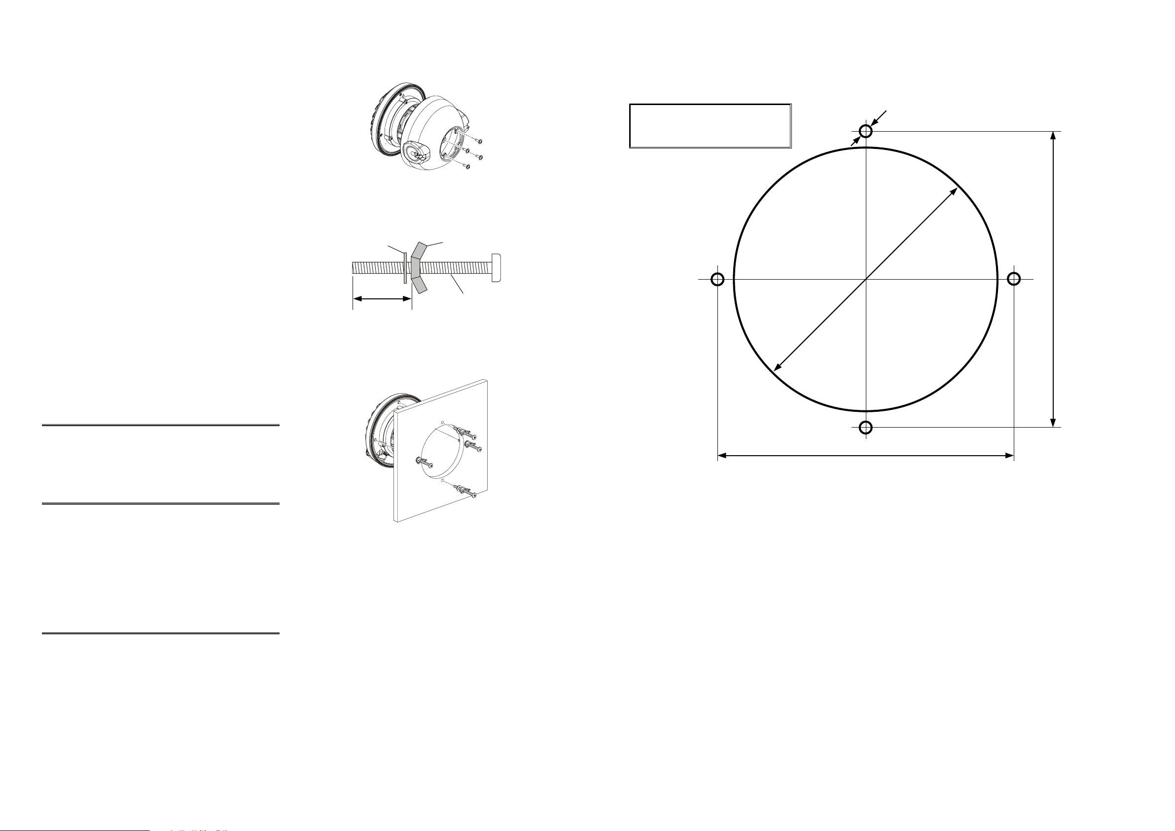
2) FLUSH MOUNT INSTALLATION
1. Remove the MLS-300i from the bracket by removing the
two Mounting Bracket Knobs, then remove the rear case
of the MLS-300i from the main body by removing the
four screws (Figure 4).
2. Assemble the supplied M4x50 Screw, Nut, and Washer as
the Figure 5.
3. Use the supplied template to mark the location where the
round hole is to be cut. Confirm the space behind the dash
or panel is deep enough to accommodate the MLS-300i
(at least 2.8 inch (70 mm) deep).
4. Cut out the round hole (one large hole and four small
mounting holes) and inset the MLS-300i from the front
side.
5. Referring to Figure 6, pass through the four M4x50 Screws
(with Nut and Washer) into the mounting holes on the panel
from the back side and turn the M4x50 Screws five times.
6. Turn the four Nuts to adjust the tension so that the MLS-
300i is tight against the mounting surface.
7. Route and secure the connection cable from the MLS-300i
to the VLH-3000 Loud Hailer. Connect the WHITE wire
of the connection cable to the “positive (+) intercom
speaker output,” the shield of the connection cable to the
“negative (–) intercom speaker,” and the YELLOW wire
of the connection cable to the “push to alert” terminal (Figure 3).
Figure 4
Washer
Wall thickness + 1 inch
Figure 5
Nut
M4x50 Screw
Use this template to mark the location
where the round hole for the flush
mount is to be cut.
TEMPLATE for the MLS-300i
φ
5
φ
95
106 mm
OPERATION (PTA FEATURE
To call the VLH-3000, press the PTA button. A calling beep
will be heard on the VLH-3000 with an indication of the intercom station (IC1 or IC2).
)
REPLACEMENT PARTS
PTA (Push To Alert) Button (Black): RA0831900
PTA (Push To Alert) Button (White): RA0815300
Mounting Bracket (Black): RA0653900
Mounting Bracket (White): RA0653800
Mounting Bracket Knobs (Black): RA045910A
Mounting Bracket Knobs (White): RA043770A
Mounting Bracket mounting hardware: U9900147
SPECIFICATIONS
Speaker Impedance:4 Ω
Maximum Power Input: 10 W
Connection Cable Length: 6.5 feet (2 m)
106 mm
Figure 6
 Loading...