

Page 1
CPN700i/CPN1010i
Multimedia Chart Plotters
Owner's Manual
Page 2

Electronic charts displayed by the CPN Series Chart Plotter are believed to be accurate and
reliable, but are not intended to be a substitute for the official charts, which should remain
your main reference for all matters related to the execution of safe navigation.
For this reason you should always keep the official published and approved nautical charts
on board.
This device complies with Part 15 of the FCC limits for Class A digital devices. This
equipment generates, uses and can radiate radio frequency energy and, if not installed or
used in accordance with the instructions may cause harmful interference with radio
communications.
There is no guarantee that interference will not occur in a particular instance. If this
equipment does cause harmful interference to other equipment, try to correct the problem
by relocating the equipment.
Consult an authorized STANDARD HORIZON dealer or other qualified service technician
if the problem cannot be corrected. Operation is subject to the following conditions: (1) This
device cannot cause harmful interference, and (2) this device must accept any interference
received, including interference that may cause undesired operation.
· The CPN Series Chart Plotter is designed for maritime use. To avoid water intrusion,
ensure the C-MAP
BY JEPPESEN SD CARD door is completely closed.
· Extensive exposure to heat may result in damage to the CPN Series Chart Plotter.
· The CPN Series Chart Plotter contains dangerous high-voltage circuits which only
experienced technicians can handle.
· STANDARD HORIZON will not be liable for errors contained herein, or for incidental
or consequential damages in connection with the performance or use of this material.
The Bluetooth® word mark and logos are owned by the Bluetooth SIG Inc., Wi-Fi® is a
registered trademark of the Wi-Fi Alliance and any use of such name by Standard Horizon
Marine Division of Vertex Standard is under license. Windows®, Windows CE®, Microsoft
Internet Explorer® and Microsoft Multimedia Player® are registered trademarks of Microsoft Corporation in the United States and/ or other countries. MicroSD™ is a trademark of
SanDisk or it subsidiaries.
Copyright 2011. VERTEX STANDARD CO., LTD. All rights reserved. Printed in Italy.
No portion of this manual may be reproduced without the permission of VERTEX STANDARD CO., LTD.
OM CODE: SH-CPN-07-X51-CE 1.00b86A & SH-CPN-10-X51-CE 1.00b87A - 211211
Page 4 Owner’s Manual
Page 3

TABLE OF CONTENTS
INTRODUCTION............................................................................................................................. 10
PACKING LIST ........................................................................................................................ 11
OPTIONAL ACCESSORIES .........................................................................................12
GENERAL OPERATION .......................................................................................................... 13
MANUAL CONVENTIONS ............................................................................................ 13
POWER UP SEQUENCE.............................................................................................. 13
POWERING OFF .......................................................................................................... 13
BRIGHTNESS CONTROL............................................................................................. 14
CHART PLOTTER FRONT PANEL............................................................................... 14
TOUCHSCREEN ........................................................................................................... 15
Touchscreen Keys ........................................................................................... 16
Touchscreen Keyboard .................................................................................... 1 6
Touchscreen Keyboard for Chart Plotter Mode ............................................... 16
Touchscreen Keyboard for other applications ................................................. 17
MENU DESCRIPTION .................................................................................................. 17
Warning Window .............................................................................................. 18
Information Window ......................................................................................... 18
SELECTING A ITEM ..................................................................................................... 18
CHART PLOTTER CONTROLS............................................................................................... 19
KEYS ............................................................................................................................. 19
PLAYING MUSIC IN BACKGROUND (for Chart Plotter Mode only) ............................ 21
Starting to play in background ......................................................................... 21
Stopping to play ............................................................................................... 22
SOFT KEYS (for Chart Plotter Mode only).................................................................... 22
MEMORY DEVICES SAFELY REMOVAL ............................................................................... 23
CHART PLOTTER .......................................................................................................................... 24
GETTING STARTED................................................................................................................ 24
CARTOGRAPHY OVERVIEW ................................................................................................. 37
Closing Soft Keys ............................................................................................ 23
SWITCHING BETWEEN MODES ................................................................................. 25
Default Mode ................................................................................................... 25
Home vs Cursor Mode..................................................................................... 25
Cursor Mode .................................................................................................... 25
Switching between 2D and 3D modes ............................................................. 26
MENU SYSTEM ............................................................................................................ 27
INITIAL SETUP .............................................................................................................28
Cursor and Menu selection speed ................................................................... 28
Changing the Ship Icon ................................................................................... 28
Selecting Course Up/North Up ........................................................................ 29
Pages Selection ............................................................................................... 29
Assigning Page Soft Keys ............................................................................... 31
Time Setup ....................................................................................................... 31
Selecting Coordinate System .......................................................................... 33
Loran TD .......................................................................................................... 33
Changing the Display Color ............................................................................. 33
Selecting Language ......................................................................................... 34
Chart Control Icon............................................................................................ 35
SETTINGS IN GENERAL SETUP MENU ..................................................................... 36
BUILT-IN CHARTS --- AVAILABLE ONLY FOR USA ................................................... 37
Updating Built-In Charts................................................................................... 38
C-MAP 4D .....................................................................................................................40
CPN700i and CPN1010i Multimedia Chart Plotters Page 5
Page 4

C-MAP 4D: MAX Content ................................................................................ 41
C-MAP 4D: FULL 4D Content .......................................................................... 41
C-MAP 4D: Value Added Data ........................................................................ 42
VALUE ADDED DATA MENU ....................................................................................... 42
REMOVING A SD CARD ......................................................................................................... 42
USING FIND SERVICES ......................................................................................................... 43
PORT SERVICES .........................................................................................................43
PORT............................................................................................................................. 44
TIDE STATIONS ........................................................................................................... 45
Changing the day ............................................................................................. 45
Changing Tide Station ..................................................................................... 45
WRECKS....................................................................................................................... 46
OBSTRUCTIONS .......................................................................................................... 46
LAKES INFORMATIONS ..............................................................................................47
QUICK AND FULL INFO ON LAKES ............................................................................ 48
LAKES BY NAME.......................................................................................................... 48
POINTS OF INTEREST ................................................................................................ 49
USER POINTS .............................................................................................................. 49
COORDINATES ............................................................................................................ 50
INFORMATIONS ........................................................................................................... 50
CHART DISPLAY FUNCTIONS ............................................................................................... 51
4D FUNCTIONS ............................................................................................................ 51
Chart Window .................................................................................................. 51
Display Mode ................................................................................................... 51
Overlay............................................................................................................. 52
Overlay Mode .................................................................................................. 52
Transparency ................................................................................................... 53
3D Exaggeration Factor ................................................................................... 53
GENERAL CHART DISPLAY FUNCTIONS .................................................................. 53
Icon Size .......................................................................................................... 53
Place Name Size ............................................................................................. 54
Safety Status Bar (DSI - Data Safety Indicator) .............................................. 54
Currents Prediction .......................................................................................... 55
Chart Language ............................................................................................... 56
Course Up/North Up ........................................................................................ 56
Nav-Aids Presentation ..................................................................................... 57
Ship Icon .......................................................................................................... 57
Course Time Line............................................................................................. 5 7
Compass Indicator ........................................................................................... 58
Ship Icon Position ............................................................................................ 58
PICTURES & DIAGRAMS............................................................................................. 58
CREATING MARKS ................................................................................................................. 60
ROUTES ..................................................................................................................................64
How to show the Pictures or Diagrams of a Object ......................................... 59
CREATING A NEW MARK USING THE CHART PAGE............................................... 60
EDITING A MARK OR WAYPOINT ..............................................................................60
DELETING A MARK OR WAYPOINT ........................................................................... 6 1
MOVING A MARK OR WAYPOINT .............................................................................. 61
MARKS/WAYPOINTS (USER POINTS) LIST............................................................... 62
CREATING/MODIFY A NEW MARK IN THE USER POINTS LIST.............................. 63
CREATING A ROUTE USING WAYPOINTS ................................................................ 65
CHANGING THE NAME OF A ROUTE......................................................................... 6 5
CREATING AN OLYMPIC ROUTE OR BOUNDARY ................................................... 66
MAKING ADDITIONAL ROUTES.................................................................................. 66
CREATING A ROUTE USING MARKS ON THE CHART PAGE .................................. 67
INSERTING A WAYPOINT INTO A ROUTE................................................................. 6 7
Page 6 Owner’s Manual
Page 5

DELETING A ROUTE.................................................................................................... 6 8
OTHER SETTINGS IN ROUTE MENU ......................................................................... 68
ROUTE CHECK ............................................................................................................ 68
EASY ROUTING (ER) ................................................................................................... 70
GOTO KEY OPERATION ........................................................................................................ 7 3
MAN OVER BOARD (MOB) FUNCTION ................................................................................. 76
TRACKS................................................................................................................................... 77
TRIP LOG ................................................................................................................................ 78
USER SD CARD ......................................................................................................................79
MAIN MENU............................................................................................................................. 82
Warning Messages .......................................................................................... 72
GOTO CURSOR ........................................................................................................... 73
GOTO A ROUTE ........................................................................................................... 7 4
Using GOTO to select Route ........................................................................... 74
Using the ShuttlePoint Knob............................................................................ 75
GOTO MARK ................................................................................................................ 7 5
PLACING A MOB POINT .............................................................................................. 76
DELETING A MOB POINT ............................................................................................ 76
SAVING AND STARTING A NEW TRACK ................................................................... 78
DELETING A TRACK .................................................................................................... 78
OTHER SETTINGS IN THE TRACK MENU ................................................................. 7 8
TRIP LOG SELECTION IN DATA WINDOW ................................................................ 78
SETUP / RESET ........................................................................................................... 79
FORMATTING THE SD CARD ..................................................................................... 8 0
TRANSFERRING FILES TO THE SD CARD ................................................................ 8 0
LOADING A FILE FROM THE SD CARD ..................................................................... 81
DELETING A FILE FROM THE SD CARD.................................................................... 8 1
REFRESHING THE SD CARD...................................................................................... 81
SELECTING A PAGE OR MENU.................................................................................. 82
CUSTOMIZING A PAGE ICON ..................................................................................... 83
CHART PAGE ............................................................................................................... 83
Single ............................................................................................................... 84
Dual.................................................................................................................. 84
Data Window Selections .................................................................................. 84
Customizing Data Windows ............................................................................. 85
Collapsing Data Windows ................................................................................ 86
Additional Functions on Chart Page: Information on Objects.......................... 87
Display Mode ................................................................................................... 88
Marine Settings ................................................................................................ 89
Depth Settings .................................................................................................89
Chart Settings .................................................................................................. 90
Underwater Objects Settings ........................................................................... 91
NAVIGATION PAGES ................................................................................................... 91
Highway Page .................................................................................................. 91
Chart/Highway Page ........................................................................................ 92
Compass Page ................................................................................................92
GPS Status Page............................................................................................. 93
Setup Menu ..................................................................................................... 93
WAAS/EGNOS Setting .................................................................................... 94
NMEA DATA PAGES .................................................................................................... 94
NMEA Display Page ........................................................................................ 94
Customizing data box in the NMEA Display Page ........................................... 95
NMEA Data Page............................................................................................. 95
FISH FINDER (optional FF525 required) ...................................................................... 96
TIDE PAGE ...................................................................................................................96
Tides ................................................................................................................ 96
CPN700i and CPN1010i Multimedia Chart Plotters Page 7
Page 6

VHF DIGITAL SELECTIVE CALLING ........................................................................... 97
NMEA 0183 Interfacing.................................................................................... 98
Distress Call..................................................................................................... 98
Position Request .............................................................................................. 98
DSC Directory .................................................................................................. 99
VIDEO INPUT ............................................................................................................... 99
Video Input menu............................................................................................. 99
Video adjustment mode ................................................................................. 100
ADVANCED SETTINGS ........................................................................................................ 101
AIS ......................................................................................................................................... 107
CONNECTION MANAGER .......................................................................................................... 111
GETTING STARTED.............................................................................................................. 111
STARTING THE CONNECTION MANAGER......................................................................... 111
CONNECTION MANAGER OVERVIEW ............................................................................... 112
HOW TO CONNECT.............................................................................................................. 113
NETWORKING CONNECTION: C-MAP 4D CHARTS,NMEA & FISH FINDER DATA SHARING 115
INTERNET BROWSER ................................................................................................................121
GETTING STARTED.............................................................................................................. 121
STARTING THE INTERNET BROWSER .............................................................................. 121
BROWSER OVERVIEW ........................................................................................................ 122
HOW TO NAVIGATE ............................................................................................................. 124
THE FAVORITE PAGES AND HISTORY LIST...................................................................... 125
THE DOWNLOAD MANAGER............................................................................................... 126
MEDIA PLAYER ........................................................................................................................... 129
GETTING STARTED.............................................................................................................. 129
STARTING MEDIA PLAYER ................................................................................................. 129
MEDIA PLAYER CONTROLS................................................................................................ 130
SAVING FILES ON A USB THUMB DRIVE........................................................................... 132
Restore Defaults ............................................................................................ 100
NAVIGATE MENU....................................................................................................... 101
Loran TD ........................................................................................................ 101
COMPASS (COG) SETUP .......................................................................................... 102
INPUT/OUTPUT (NMEA) CONNECTIONS................................................................. 102
Input/Output ................................................................................................... 102
NMEA 0183 output sentences ....................................................................... 103
ALARMS...................................................................................................................... 103
SIMULATION .............................................................................................................. 104
Navigating a Route in Simulation mode ........................................................ 104
DSC POLLING ............................................................................................................105
ABOUT PAGE ............................................................................................................. 105
DAM Report Page.......................................................................................... 106
SYSTEM DEFINITIONS .............................................................................................. 107
MENU .......................................................................................................................... 108
QUICK INFO ON AIS TARGET................................................................................... 108
LIST ............................................................................................................................. 109
AIS TARGET COLORS ............................................................................................... 109
Wi-Fi® CONNECTION ................................................................................................ 112
CONNECTION MANAGER CONTROLS ....................................................................113
AUTHENTICATION/ENCRYPTION PROTOCOLS ..................................................... 114
CPN SERIES CHART PLOTTER SETUP ................................................................... 115
Chart Plotter 1 Setup (with C-MAP 4D CARD inserted) ................................ 116
Chart Plotter 2 Setup (no chart inserted) ....................................................... 118
Custom Setup ................................................................................................ 120
INTERNET BROWSER CONTROLS .......................................................................... 123
THE SIGNAL INDICATOR ICON ................................................................................ 125
FAVORITES ................................................................................................................ 125
Page 8 Owner’s Manual
Page 7

VIEWING AND PLAYING FILES ........................................................................................... 132
INSTALLATION ............................................................................................................................ 134
MOUNTING THE CPN SERIES CHART PLOTTER .............................................................. 134
BRACKET MOUNTING ............................................................................................... 134
FLUSH MOUNTING THE CPN SERIES CHART PLOTTER ...................................... 135
MOUNTING THE OPTIONAL EXTERNAL GPS ANTENNA.................................................. 137
CONNECTIONS............................................................................................................................ 138
SPECIFICATIONS ........................................................................................................................ 149
TECHNICAL TESTS ..................................................................................................................... 155
SYSTEM UPDATE ....................................................................................................................... 157
TERMS ......................................................................................................................................... 161
ANALYTICAL INDEX ...................................................................................................................164
FLUSH MOUNTING THE ANTENNA .......................................................................... 137
OVERVIEW............................................................................................................................ 138
BATTERY CONNECTIONS ........................................................................................ 139
NMEA 0183 CONNECTIONS...................................................................................... 140
PWR/ACC1 Connections ............................................................................... 141
ACC 2 Connections ......................................................................................141
PORT Input selections................................................................................... 141
PORT Output sentences................................................................................ 142
CPN Series Chart Plotter to NMEA 0183 connection examples ................... 142
VIDEO INPUT CONNECTOR ..................................................................................... 144
VIDEO INPUT CONNECTIONS for CPN700i ............................................................. 144
VIDEO INPUT/OUTPUT CONNECTIONS for CPN1010i............................................ 145
PRE-AMP OUTPUT - EXTERNAL AMPLIFIER/SPEAKER CONNECTIONS............. 145
CPN Pre-Amp connector pin out ................................................................... 146
OPTIONAL USB THUMB DRIVE ................................................................................ 146
OPTIONAL EXTERNAL ALARM CONNECTION ........................................................ 147
OPTIONAL GPS ANTENNA........................................................................................ 147
OPTIONAL FF525 BLACK BOX FISH FINDER .......................................................... 147
SECOND CPN TO SHARE C-MAP 4D CHARTS, NMEA & FF DATA ....................... 148
NMEA 2000 DEVICES and ETHERNET RADAR (for future release)......................... 148
CPN700i ................................................................................................................................. 149
DIMENSIONS.............................................................................................................. 150
CPN1010i ............................................................................................................................... 150
DIMENSIONS.............................................................................................................. 151
OPTIONAL FF525 FISH FINDER .......................................................................................... 152
OPTIONAL WAAS GPS RECEIVER .....................................................................................153
GPS CONNECTION IMAGE ....................................................................................... 154
SYSTEM TEST ......................................................................................................................155
RAM MENU (RESET).................................................................................................. 155
RAM Clear ..................................................................................................... 155
BACKLIGHT ................................................................................................................ 156
CARTRIDGES (used by Standard Horizon Technicians)............................................ 156
Internal Data Base Test ................................................................................. 156
SD CARD Test ............................................................................................... 156
SERIAL PORTS (used by Standard Horizon Technicians) ......................................... 156
Change Parameters....................................................................................... 156
Input Data Display ......................................................................................... 156
Loop-Back Test.............................................................................................. 156
SYSTEM UPDATE PROCEDURE ......................................................................................... 157
SYSTEM UPDATE ERROR MESSAGES.............................................................................. 158
ERROR MESSAGES 01, 02, 03, 04, 05, 06, 07, 09 ................................................... 158
ERROR MESSAGE 08................................................................................................ 159
ERROR MESSAGES 20, 21, 22 ................................................................................. 159
CPN700i and CPN1010i Multimedia Chart Plotters Page 9
Page 8

INTRODUCTION
Congratulations on your purchase of the STANDARD HORIZON CPN Series Chart Plotter.
Whether this is your first Navigation device, or if you have other STANDARD HORIZON
equipment, STANDARD HORIZON organization is committed to ensuring your enjoyment
of this Navigation device. STANDARD HORIZON technical support personnel stand behind
every product we sell. Our Product Support team invites you to contact us should you
require technical advice or assistance, for USA users at 800/767-2450 or
marinetech@vxstdusa.com, for European users at +44 1962 866667 or e-mail at
marinetech@yaesu.co.uk.
Information in this Owner’s Manual is subject to change without notice.
The CPN700i and CPN1010i are precision-crafted high-performance receivers for the
Global Positioning System (WAAS GPS) constellation of satellites. The internal or optional
GPS antenna provides precise location data with a host of navigation features ideal for
nautical use. The CPN700i and CPN1010i are housed in rugged, impact-resistant cases
with outstanding ergonomic design for effortless operation. The CPN700i and CPN1010i
are IP57 waterproof.
The advanced features of the CPN Series Chart Plotter include:
· Built-In Charts
2
for coastal navigation of USA including Alaska, Hawaii and Great
Lakes, Canada, Bahamas, Caribbean, Cuba, Mexico, Puerto Rico, and Central
America. Fresh water coverage is not included. Detailed coverage and Fresh waters
charts are available from Jeppesen.
· Optional C-MAP 4D cartography:
3D View
Satellite Images
Raster Charts
Easy Routing
Value Added Data
· Display:
Sunlight viewable
Bonded with bright LED (1000 nits) backlight
CPN700i: 7” Wide VGA 800x480
CPN1010i: 10” Wide SVGA 1024x600
· Optional 50 channel WAAS GPS antenna with 30 Feet of cable
· Network interfaces:
Built-In Wi-Fi® and Bluetooth®
1
capability
Built-In Internet Explorer® 6.0 and Windows Multimedia Player®
USB 2.0 Connection compatible keyboard1 or memory stick
NMEA 2000
1
· Front panel stereo and pre-amp outputs for optional audio amp
· Video Input:
CPN700i: 1 NTSC or PAL
CPN1010i: 2 NTSC or PAL
Page 10 Owner’s Manual
Page 9

· AIS, FF525 Fish Finder and Si-Tex/Koden Radar1 compatible capable
· Dual chart windows with independent zoom levels
· Selectable Sail boat and Power boat Ship Icons
· Compass Rose indication around Ship Icon
· Route checking
· Guardian Alarm
· Color Targets AIS
· Dedicated AIS List page
· Navigate to an Olympic Route
· Displays DSC Distress and Position Report calls received from a DSC VHF radio
· 3-years waterproof warranty
1
Available in future software versions.
2
Only for USA.
PACKING LIST
When the package containing the Navigation device is first opened, please check for the
following contents. If any parts are missing, contact the dealer this Navigation device was
purchased from.
Accessories and replacement parts may be ordered from STANDARD HORIZON’s Parts
Department for USA users at 714/827-7600 extension 6800 or e-mail at
yaesuparts@vxstdusa.com, for European users at +44 1962 866667 or e-mail at
marinetech@yaesu.co.uk.
PART CODE ITEM
S8003046 External bracket (CPN700i)
S8003043 External bracket (CPN1010i)
S8003048 Bracket knob
S8003045 Dust cover (CPN700i)
S8003042 Dust cover (CPN1010i)
T9101553 PWR ACC1 & ACC2 cable
S8003044 Flush Mount Bracket
XUCMP0052 2 Amp fuse and holder
EM052U100 Owner’s Manual
EM052U500 Quick Reference Guide
CPN700i and CPN1010i Multimedia Chart Plotters Page 11
Page 10
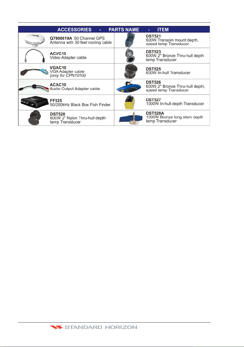
OPTIONAL ACCESSORIES
Page 12 Owner’s Manual
Page 11
GENERAL OPERATION
MANUAL CONVENTIONS
This Owner’s Manual includes information for both the 7inch CPN700i and 10inch
CPN1010i Multimedia Chart Plotters which are referenced to CPN Series Chart Plotters
throughout this manual. In addition when a word(s) is bold and underlined it is referring to
a menu selection on the display.
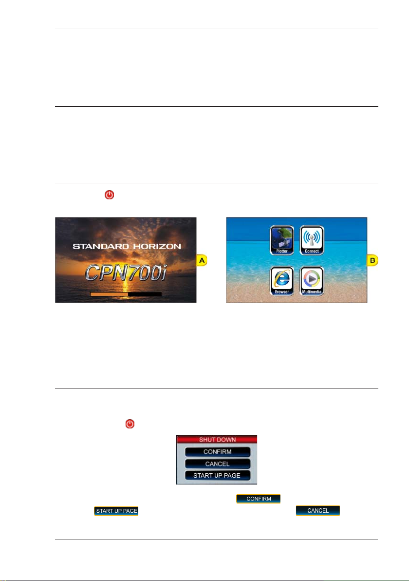
POWER UP SEQUENCE
1. Press the PWR key until the display shows the Splash Screen page (see A). In case
of error messages please refer to System Update Error Messages paragraph.
2. After about 1 minute the Splash Screen will change to show the Start Up Screen (see B).
This page allows selection of the Chart Plotter, Media Player (video, audio and images),
Internet Browser and Connection Manager (for Wi-Fi®, Bluetooth® and Ethernet setup).
If a selection is not made within 30 seconds, the CPN Series Chart Plotter automatically
changes to Chart Plotter Mode.
POWERING OFF
1. The CPN Series Chart Plotters have three operations. The GPS Chart Plotter Mode,
Internet and Multimedia modes. When the CPN Series Chart Plotter is in any of these
modes and the
2. To turn off the CPN Series Chart Plotter, tap on . To show the Start Up page
tap on
CPN700i and CPN1010i Multimedia Chart Plotters Page 13
PWR key is pressed and held, a Shut Down window will be shown:
. To exit from the Shut Down menu, tap on .
Page 12
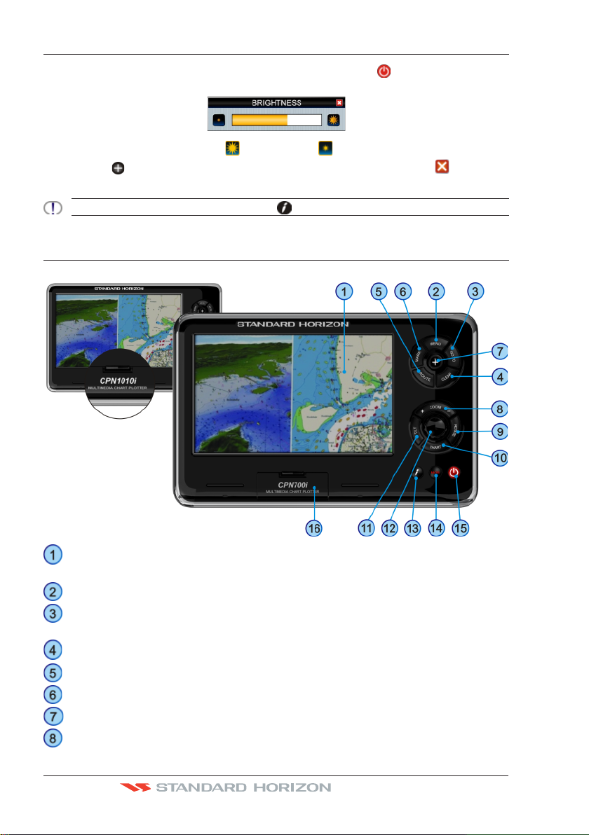
BRIGHTNESS CONTROL
With the CPN Series Chart Plotter turned On, briefly press the PWR key to show the
brightness control window.
On the Brightness window, tap on to increase or to decrease the display backlight
(or move the
selection and exit the brightness setting mode.
The Brightness control is avaible also using the Intelligent key.
ShuttlePoint Knob to the right or left); when finished, tap on to save the
CHART PLOTTER FRONT PANEL
Touchscreen touch the screen to interact with the Chart Page, Menus, Internet
or Multimedia modes.
MENU Key selects the Main Menu
GOTO Key shows the GOTO popup window and allows selection of Go To
Cursor, Saved Mark or Route
CLEAR Key cancels current operation
ROUTE Key creates Waypoints to make a Route when on the Chart Page
MARK Key places a Mark when on the Chart Page
ShuttlePoint Knob moves the cursor on the Chart Page and to select items in menus
ZOOM Keys change the scale of the chart to show a smaller or a wider area.
Page 14 Owner’s Manual
Page 13
When pressed allows the Rotary knob to be used to change zoom
levels
ROTATE Key enables the chart to be rotated using the Rotary Knob
CHART Key opens a menu to change the chart from 2D to 3D and show vector,
vector/sat, raster or satellite charts
TILT Key enables the chart to be tilted using the Rotary Knob
Rotary Knob used to enter a function or rotate, tilt and zoom In or Out the chart
MOB Key places a Man Overboard Mark
Intelligent Key opens a menu window to enable the Internet Browser or Media
Player, and to show Brightness and Touchscreen Calibration too.
Internet cannot be accessed whilst in Chart Mode, however playing audio files using the multimedia player
may be done simultaneously during Chart Plotter operation.
Power Key turns On/Off the CPN Series Chart Plotter and adjust brightness
SD Card slot used to insert optional C-MAP 4D cartography, view pictures and
listen to audio files loaded on optional card, save User Points and
update software
TOUCHSCREEN
The CPN700i and CPN1010i use a touchscreen display. Many functions are controlled by
touching the display or using the dedicated keys, ShuttlePoint or Rotary Knobs.
The Touchscreen Calibration can be started from the Start Up screen by pressing and holding the
key for 5 seconds, or by pressing the Intelligent key from any screen other than Setup.
Once the calibration screen is displayed, you must tap on the center of the Cross-Hair as it
moves around the screen, following the procedure shown. When completed and prompted
press the ENTER key (
to complete the calibration process and store the settings. Calibration mode may be exited
without storing the settings by pressing the
ShuttlePoint Knob, see the following “Selecting an item” paragraph)
key.
Cleaning of the CPN Series Chart Plotter screen is a very important operation and must be done carefully.
Since the surface is covered by a anti-reflective coating, the procedure for cleaning all the surfaces can
be performed using the following procedure: use a clean, soft, lint-free cloth to clean the glass. We
recommend using a micro-fiber cloth. Spray a small amount of ammonia-free cleaner (isopropyl alcohol)
onto the cloth. Spraying on the cloth will prevent overspray. Fold the cloth or lens cloth into a triangular
shape, moisten the tip and use the index finger behind a corner to move the cloth across the surface in
overlapping side to side strokes. If the cloth is too wet, a noticeable wet film will be left in its path and you
will need to repeat the process. If too dry, the cloth won’t glide easily, and may damage the surface.
Below is a list of common functions accessed by touching the display:
· Menu items
· Page selection
· Keyboard input
· Page sweeping
· Scroll bar movements
· Panning the chart
CPN700i and CPN1010i Multimedia Chart Plotters Page 15
Page 14
· Pointing and manipulating objects on the chart (cartographic and user objects)
· Moving the cursor
· Chart rotation, Panning, Tilting and Zooming
When touching an active object on the screen, the system provides a visual feedback to the show object
has been touched (for example the object changes its color when touched).
The following gestures are recognized and interpreted:
· Flick (Page Sweeping): press a finger on the screen, quickly move the finger left or
right, and then lift up the finger to initiate scrolling.
· Pan/Move (Scrolling maps, moving cursor): press and hold a finger on the screen and
then drag the finger in any direction.
· Tap (Placing a cursor, activating Soft Keys, selecting objects/Data Boxes/options in
menu): shortly press and release a finger on the screen.
· Hold (Opening additional related options context depended): press and hold a finger
on the screen.
Touchscreen Keys
The keys that appear on the screen can be in four states:
·
·
be moved using the ShuttlePoint Knob; if the ShuttlePoint Knob or the Rotary Knob is
pressed, the key related function is executed.
·
released its related function is started.
·
moment.
: (BLUE BACKGROUND) key is not selected and not touched.
: (BLUE BACKGROUND WITH YELLOW FRAME) key is selected. The selection can
: (RED BACKGROUND) key is touched with a finger. When a key is touched and
: (GREY BACKGROUND) the function assigned to this key is not available at the
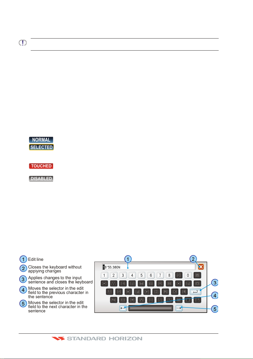
Touchscreen Keyboard
A keyboard is used to enter/editing text of User Points or typing a URL when using the
Internet Browser. The keyboard is also used for Internet Browser, MediaPlayer and
Configuration Manager. The keyboard can be operated by the touchscreen or by moving
the ShuttlePoint Knob. A character is entered (turns red) when the key is tapped once or
when ShuttlePoint Knob is pressed.
Touchscreen Keyboard for Chart Plotter Mode
Page 16 Owner’s Manual
Page 15
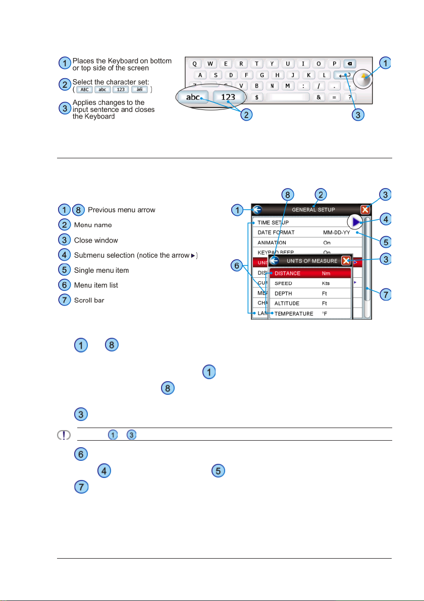
Touchscreen Keyboard for other applications
MENU DESCRIPTION
The menu window has the following elements.
Refer to the previous picture:
and : a single touch on the arrow icon closes the current menu and displays the
·
previous menu level. In the first menu level it closes the menu and goes back to the Main
Menu page (in the example below
to the Main Menu page.
Setup menu).
: when touched closes all menus.
·
Touching or in the first menu level has no effect if there is a opened submenu.
· : list of all menu items present on the current menu level. There are two types of menu
items: opens the next menu level. allows choosing one of available options.
: when touched up/down the bar, scrolls the content of the related window/page.
·
See the following picture.
CPN700i and CPN1010i Multimedia Chart Plotters Page 17
closes the Units of Measure menu and displays the General
closes the General Setup menu and goes back
Page 16
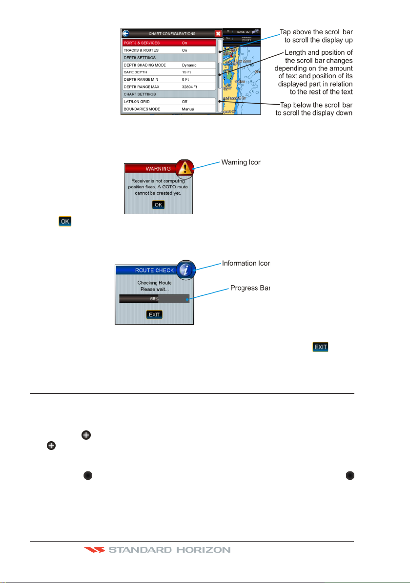
Warning Window
The Warning window will be shown to alert you of critical situations. For example:
Tap on to close the Warning window.
Information Window
Above you can see an example of Information window that shows the CPN Series Chart
Plotter is computing something. You can choose to wait unit done or tap on
display to exit.
on the
SELECTING A ITEM
To select and activate a desired item:
· tap your finger on the display over the item
or
· move the
ShuttlePoint Knob (if enabled, see SHUTTLEPOINT ENTER item in “Settings in
General Setup Menu” paragraph, “Chart Plotter” section)
or
· move the
Rotary Knob
Refer to the following example:
ShuttlePoint Knob up/down to place cursor on the item and then press the
Rotary Knob left/right to place cursor on the item and then press the
Page 18 Owner’s Manual
Page 17
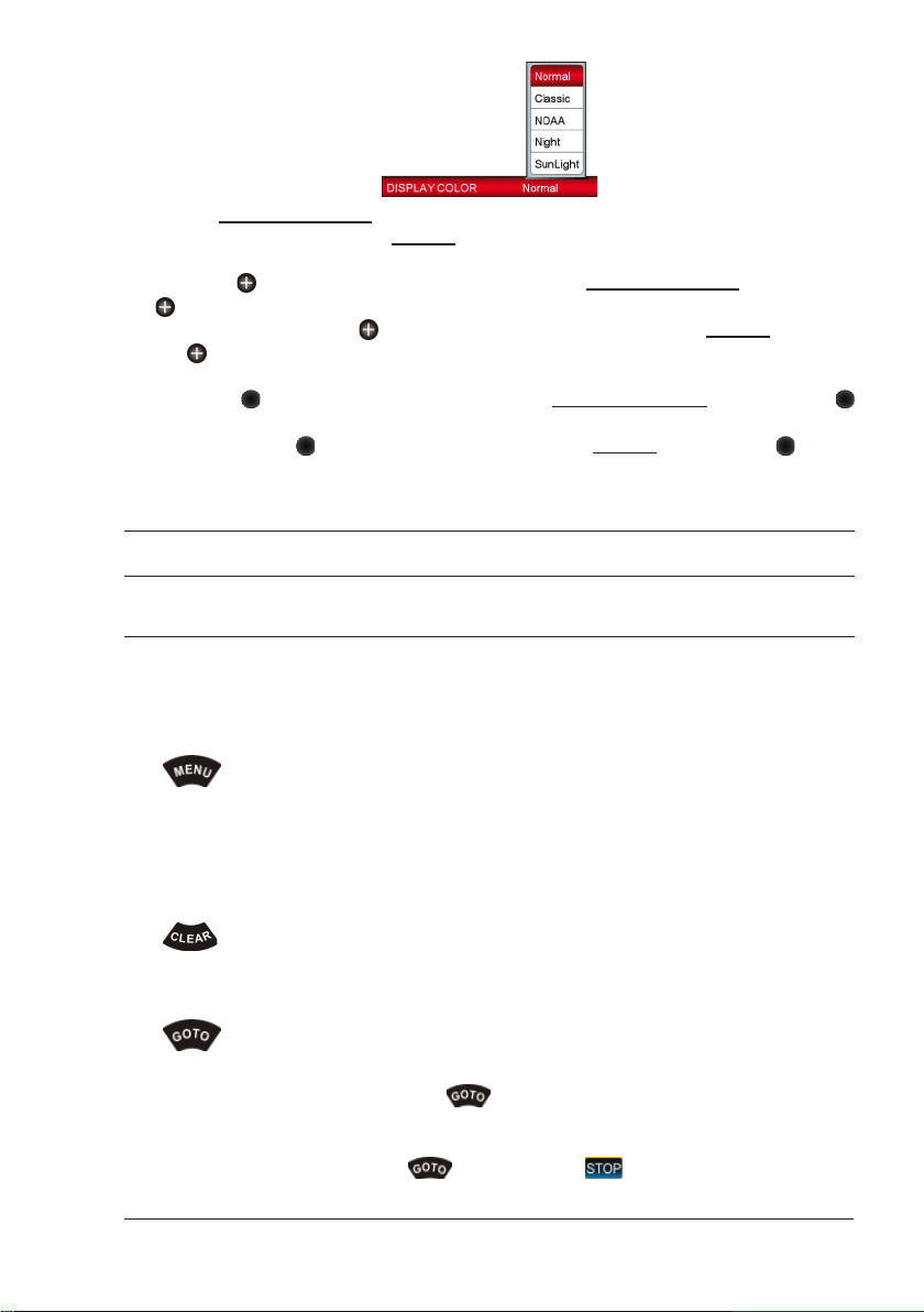
A. Tap on DISPLAY COLOR. A popup window will be shown with the available options.
To set Normal palette tap on
or
B. Move the
ShuttlePoint Knob. A popup window will be shown with the available options. To s et
Normal palette move the
the
or
C. Move the
Rotary Knob. A popup window will be shown with the available options. To se t N ormal
palette move the
Knob.
ShuttlePoint Knob up/down to highlight DISPLAY COLOR and press the
ShuttlePoint Knob.
Rotary Knob left/right to highlight DISPLAY COLOR and press the
Rotary Knob left/right to highlight Normal and press the Rotary
Normal.
ShuttlePoint Knob up/down to highlight Normal and press
CHART PLOTTER CONTROLS
KEYS
The CPN700i and CPN1010i in addition to being able to control functions with the touch
display, for your convenience dedicated keys and knobs are also provided. You will notice
when a key is pressed a single beep will be produced which means the key press is valid.
When a key press is not valid the CPN Series Chart Plotter will produce 3 beeps.
The
· Press from any page in the Chart Plotter Mode to open the Main Menu.
· Press and hold for 3 seconds to allow you to change the fields contained within the data
·
The
· When pressed, exits from a menu, from a selection, closes a Soft Key, changes from
The
ACTIVE ONLY IN CHART PLOTTER MODE
· While on the Chart Page, press the key when you desire to Goto to a destination.
· When pressed, a popup window will be shown allowing you to start navigating to the
· To stop navigating, press the
CPN700i and CPN1010i Multimedia Chart Plotters Page 19
key
windows.
ONLY FROM THE START UP SCREEN: Press and hold for 5 seconds to enable the Touchscreen
Calibration mode.
key
Cursor Mode to Home Mode or exits from a page to the Chart Page.
key
position of the Cursor, a saved Mark or Route.
key and tap on .
Page 18
The key
ACTIVE ONLY IN CHART PLOTTER MODE
· When a Chart Page is selecte d , pressing the key places a Mark under the ship’s
position when in Home Mode, or under the cursors position.
· Pressing and holding for 3 seconds allows you to open the Marks/Wpt List page.
The
ACTIVE ONLY IN CHART PLOTTER MODE
key
· When on Chart Page places a Waypoint under the vessel’s or cursor position.
· Succeeding presses places additional Waypoints to form a Route.
· Pressing and holding for 3 seconds allows you to open the Edit Route page.
The
ShuttlePoint Knob (joystick)
· Moves the cursor around the Chart Page (Cursor mode) and pans the chart.
· Used to scroll and select menu items. It changes the CPN Series Chart Plotter from
Home Mode to Chart Mode on the chart screen.
· Press to select or enter a function (user selectable, see SHUTTLEPOINT ENTER item
in “Settings in General Setup Menu” paragraph, “Chart Plotter” section).
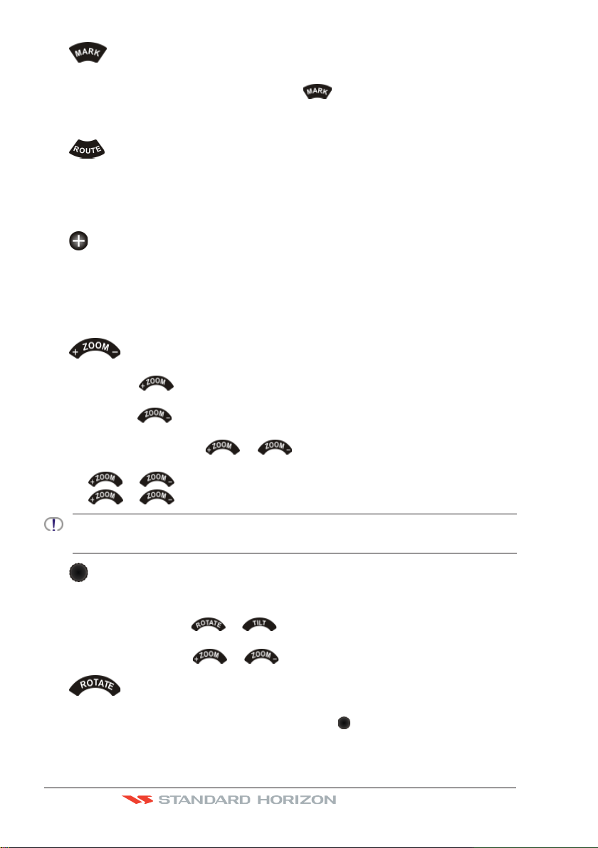
The
ACTIVE ONLY IN CHART PLOTTER MODE
keys
· Pressing the key shows more detail of a smaller area, by changing the chart
scale and zooming in on your display.
· Pressing the
key changes the scale and show a wider, otherwise less detailed
view.
· Pressing and holding the or key allows for quick zoom, that is the fast
change of the chart scale where only the land areas are drawn.
· the
· the
The CPN Series Chart Plotters contains Built-In cartography for Alaska, Hawaii and Great Lakes, Canada,
Bahamas, Caribbean, Cuba, Mexico, Puerto Rico, and Central America (Only for USA users). For more
detail, a C-MAP 4D SD CARD must be purchased and installed.
or key is released all map details are shown.
or key changes the Rotary Knob mode to zooming.
The Rotary Knob
· Used to scroll and select menu items.
· Press to select or enter a function.
· Used together with the
or key allows rotating or tilting the chart display
both in 3D and in 2D mode.
· Used together with the or key allows zooming.
The key
ACTIVE ONLY IN CHART PLOTTER MODE
· To rotate the chart: press this key, then rotate the Rotary Knob. The rotate angle
ranges from 0 to 359 degrees.
Page 20 Owner’s Manual
Page 19
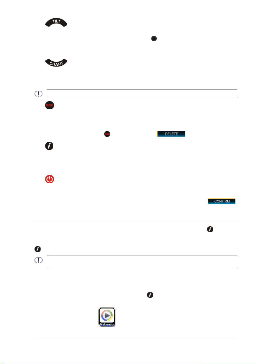
The key
ACTIVE ONLY IN CHART PLOTTER MODE
· To tilt the chart: press this key, then rotate the Rotary Knob. The tilt angle ranges
from 90 to 11 degrees (90 is the view from the top). Clockwise rotation increases the
tilt angle, counterclockwise rotation decreases the tilt angle.
The
ACTIVE ONLY IN CHART PLOTTER MODE ON CHART PAGE ONLY
key
· Opens the CHART DISPLAY menu window from which you can select 2D Vector,
Vector/Satellite, Raster or 3D Vector, Satellite or Raster modes.
Optional C-MAP 4D cartography is needed to see Raster and Satellite details on the chart.
The key
ACTIVE ONLY IN CHART PLOTTER MODE
· When pressed, places a MOB (MOB = Man Over Board) mark on the Chart Page under
the boat’s position to aid in the rescue or a person that may have fallen aboard.
· To delete MOB, press the
key and then tap on on the popup window.
The Intelligent key
· Exits the Chart Plotter Mode and shows a window to select a Internet Browser or play
audio files, and to select Brightness and Touchscreen Calibration.
· PLAYING MUSIC in BACKGROUND (see following paragraph)
The
PWR key (Brightness)
· Pressing and holding turns the CPN Series Chart Plotter On.
· Once On, pressing momentarily, shows the display brightness adjustment window.
· To turn Off, press and hold until the SHUTDOWN menu is shown, then tap on
PLAYING MUSIC IN BACKGROUND (FOR CHART PLOTTER MODE ONLY)
It is possible to play audio files when in Chart Plotter Mode by pressing the Intelligent
key to access Media Player from the Chart Plotter Mode.
Once the Media Player is running as background application on the Chart Plotter Mode, the
Intelligent key can toggle between the Chart Plotter and Media Player and back.
The Media Player is the only application that can be activated from the Chart Plotter Mode. It is not possible
to enter the Internet Browser when the Media Player and the Chart Plotter are both active.
.
Starting to play in background
To play music in background when running Chart Plotter Mode, follow the procedure below:
1. While Chart Plotter Mode is running, press the
the options Browser and Multimedia is shown.
2. Tap on Multimedia Icon
CPN700i and CPN1010i Multimedia Chart Plotters Page 21
. The Media Player is opened.
Intelligent key. A pop-up window with
Page 20
3. Choose a song to play, adjust the play mode and volume (see Media Player section for
more information).
4. Press the
Intelligent key to go back to Chart Plotter Mode. The Media Player is hidden
but it is active (music is playing) and the Chart Plotter Mode is shown again.
Pressing the
Intelligent key toggles between Media Player and Chart Plotter Modes.
Stopping to play
To stop music in background when running Chart Plotter Mode, follow the procedure below:
1. While Chart Plotter Mode is running, press the
2. Tap on
in Media Player Mode. Media Player is closed completely (without closing
Intelligent key.
Chart Plotter) and the Chart Plotter Mode is shown again.
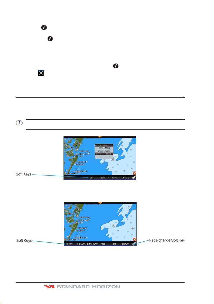
SOFT KEYS (FOR CHART PLOTTER MODE ONLY)
The CPN Series Chart Plotters have Soft Keys which are show on the display when:
· Chart Page
The cursor is moved over the top of a item (Mark, Waypoint, Route, chart object
1
Only if the Auto Info option is enabled, see the “Settings in General Setup Menu” paragraph, “Chart Plotter”
section.
1
...)
· Chart Page
Touch and hold the Page Change Key (refer to the image below) to show Soft Keys to
access other pages.
· Other Pages (Tide, Highway, Compass, GPS and Fish Finder Pages)
Tap anywhere on the page to show the Soft Keys:
Page 22 Owner’s Manual
Page 21
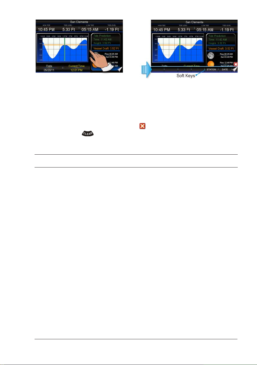
Closing Soft Keys
The Soft Keys are closed in the following ways while in Chart Plotter Mode:
· will automatically be removed if the display is not pressed from more than a specific
timeout user selectable (see the Home Mode Revert setting in the “Settings in General
Setup Menu” paragraph, “Chart Plotter” section).
· by tapping on the Close Soft Key control
· by pressing the
key.
.
MEMORY DEVICES SAFELY REMOVAL
To replace an SD CARD with no chart data or a USB memory stick remove the device and
wait at least 7 seconds before inserting the new one.
To remove an SD CARD with chart data during the CPN Series Chart Plotter working follow
the procedure described in the Chart Plotter section.
CPN700i and CPN1010i Multimedia Chart Plotters Page 23
Page 22
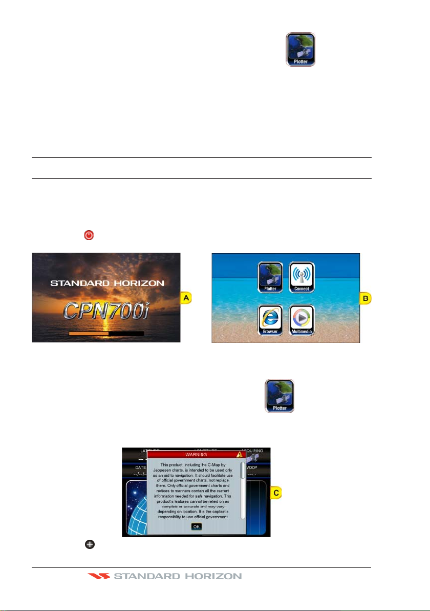
CHART PLOTTER
GETTING STARTED
This section takes you through the most frequently used operations and shows how to
customize the appearance of the CPN Series Chart Plotter.
1. Press the PWR key until the display shows the Splash Screen page (see A). In case
of error messages please refer to System Update Error Messages paragraph.
2. After about 1 minute the Splash Screen will change to show the Start Up Screen (see B).
This page allows you to select the Chart Plotter, Connection Manager, Internet Browser
or Multimedia modes.
3. To select the Chart Plotter mode, tap on the Plotter Icon
The CPN Series Chart Plotter will automatically change to Chart Plotter Mode if a key
or display is not touched for 30 seconds.
4. The Splash Screen page (see A) is shown again before the Warning page appears (see C).
Move the ShuttlePoint Knob down or touch underneath the scroll bar to read the
Page 24 Owner’s Manual
.
Page 23
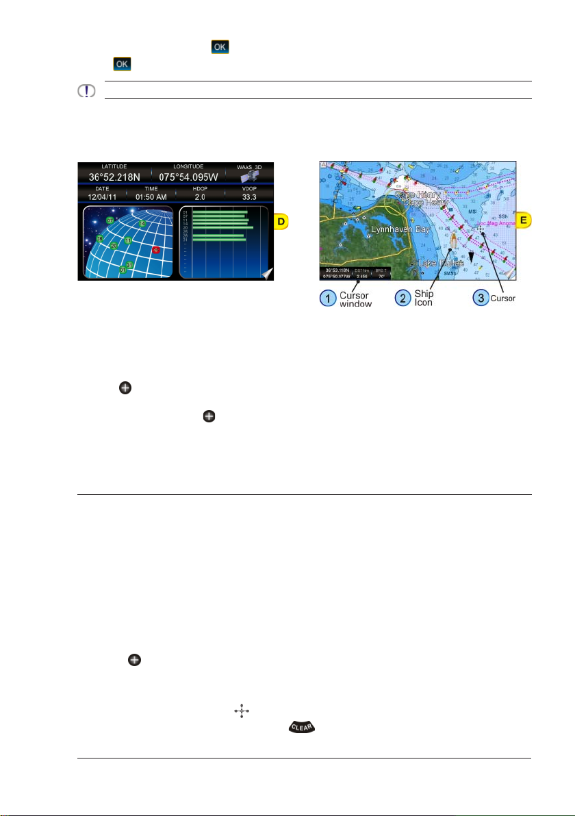
Warning page. Tap on to accept the terms. Other Warning pages might appear, tap
to confirm.
on
ONLY FOR USA: If Built-In Charts are out of date other warning pages are displayed.
5. When a CPN Series Chart Plotter is first turned on it will take some time for the GPS to
acquire a fix of your position. During this time the GPS Status Page (see D) will be shown.
This page shows signals strengths and locations of GPS satellites. After a fix is received
the page will be changed to show the vessel’s position on the Chart Page (see E).
5. After the Chart Page is shown (see E), the vessel will be show in the center of the display.
CPN Series touch display operations:
· Single tap: move the cursor to a location
· Swipe (touch and drag finger): pan the chart to see a different area on the chart
· Quick swipe (touch and quickly drag finger): change page
ShuttlePoint Knob when moved will change the location of the cursor. When the
The
cursor reaches the edge of the chart, the chart will pan.
6. When you move the
Cursor window change. This shows the Distance and Bearing from the GPS Fix of your
vessel to the position of the Cursor.
ShuttlePoint Knob you will notice DST and BRG values in the
SWITCHING BETWEEN MODES
Default Mode
The Chart Page in 2D Vector is the default page. The Ship Icon (position fix) is in the center
of the screen (Home Mode): as the ship moves through the water the vessel’s position will
be kept in the center of the display.
Home vs Cursor Mode
By default the CPN Series Chart Plotter shows the vessel in the center of the display which
is called Home Mode. To change from Home Mode to Cursor Mode, touch the display or
move the
ShuttlePoint Knob.
Cursor Mode
In Cursor Mode the Cross-Hair is shown on the chart. To exit this mode so the Boat Icon
stays in the center of the chart press the
CPN700i and CPN1010i Multimedia Chart Plotters Page 25
key.
Page 24

Cursor Mode allows you to pan around and look at areas on the chart. In this mode you can
also create Marks, Routes, measure distance and bearings from your current position.
The CPN Series Chart Plotter will automatically exit from Cursor Mode to Home Mode if the
display or a key is not pressed for a user selectable time. The timeout depends on the Home
Mode Revert setting in the General Setup menu (see “Settings in General Setup Menu”
paragraph, “Chart Plotter” section). Default is 1 minute.
Switching between 2D and 3D modes
There are two methods to toggle between 2D and 3D modes:
From Main Menu
1. The Chart Page in 2D mode is shown (see A). Press the
Menu icon.
2. Tap on the small
(see B).
3. Tapping on DISPLAY MODE selects between 2D and 3D.
4. When 3D has been selected (see C), press the
shows the Chart Page in 3D (see D).
DISPLAY icon on the Desktop. The Chart Display menu appears
key, tap on the large Setup
key to exit from menu. The screen
Using the key
1. The Chart Page in 2D mode is shown (see A).
Press the key: the following menu appears (see B).
Page 26 Owner’s Manual
Page 25
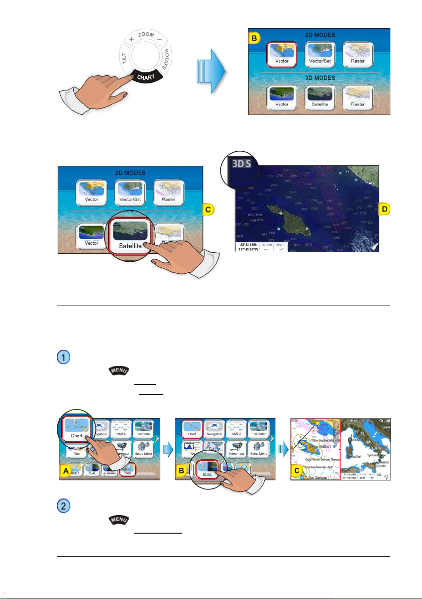
2. To select the 3D mode tap on a desired 2D or 3D icon among the available ones.
3. As soon as the desired 3D icon has been tapped (see C), the screen shows the selected
Chart Page in 3D (see D).
MENU SYSTEM
The CPN Series Chart Plotters have a unique menu system which allows you to select a
page and see subpages on a desktop to make choices quick and easy.
See the following examples of how to select a page:
Dual Chart example
1. Press the
2. Tap on the large
3. Tap on the small
(see C).
key from any page.
Chart icon (see A) to select a page.
DUAL icon (see B) on the Desktop to show the Dual Chart page
Setup Menu example
1. Press the
2. Tap on the large
CPN700i and CPN1010i Multimedia Chart Plotters Page 27
key from any page.
Setup Menu icon (see A) to select a page.
Page 26
3. Tap on the small GENERAL icon (see B) on the Desktop to show the General Setup
page (see C).
INITIAL SETUP
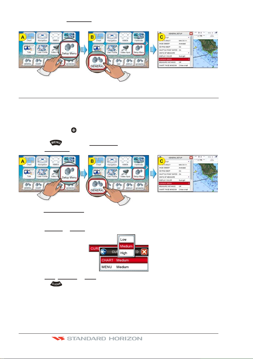
Cursor and Menu selection speed
The CPN Series Chart Plotter allows you to control the speed the Cursor moves on the chart
and in menus using the
speed follow the procedure below:
1. Press the
2. Tap on
GENERAL (see B). The General Setup menu appears (see C).
ShuttlePoint Knob. The default setting is Medium, to change the
key, tap on Setup Menu (see A).
3. Tap on CURSOR SPEED. The menu now shows two selections, Chart and Menu which
allow the Cursor Speed to be selected as High, Medium or Low on the Chart Page or
within the menus.
4. Tap on
5. Tap on Low, Medium or High to set the desired speed.
6. Press the
7. Move the cursor on the Chart Page and see if the speed is to your liking.
CHART or MENU.
key repeatedly until the menu disappears.
Changing the Ship Icon
The Ship Icon may be changed to one of the following icons for Sail or Power:
Page 28 Owner’s Manual
Page 27
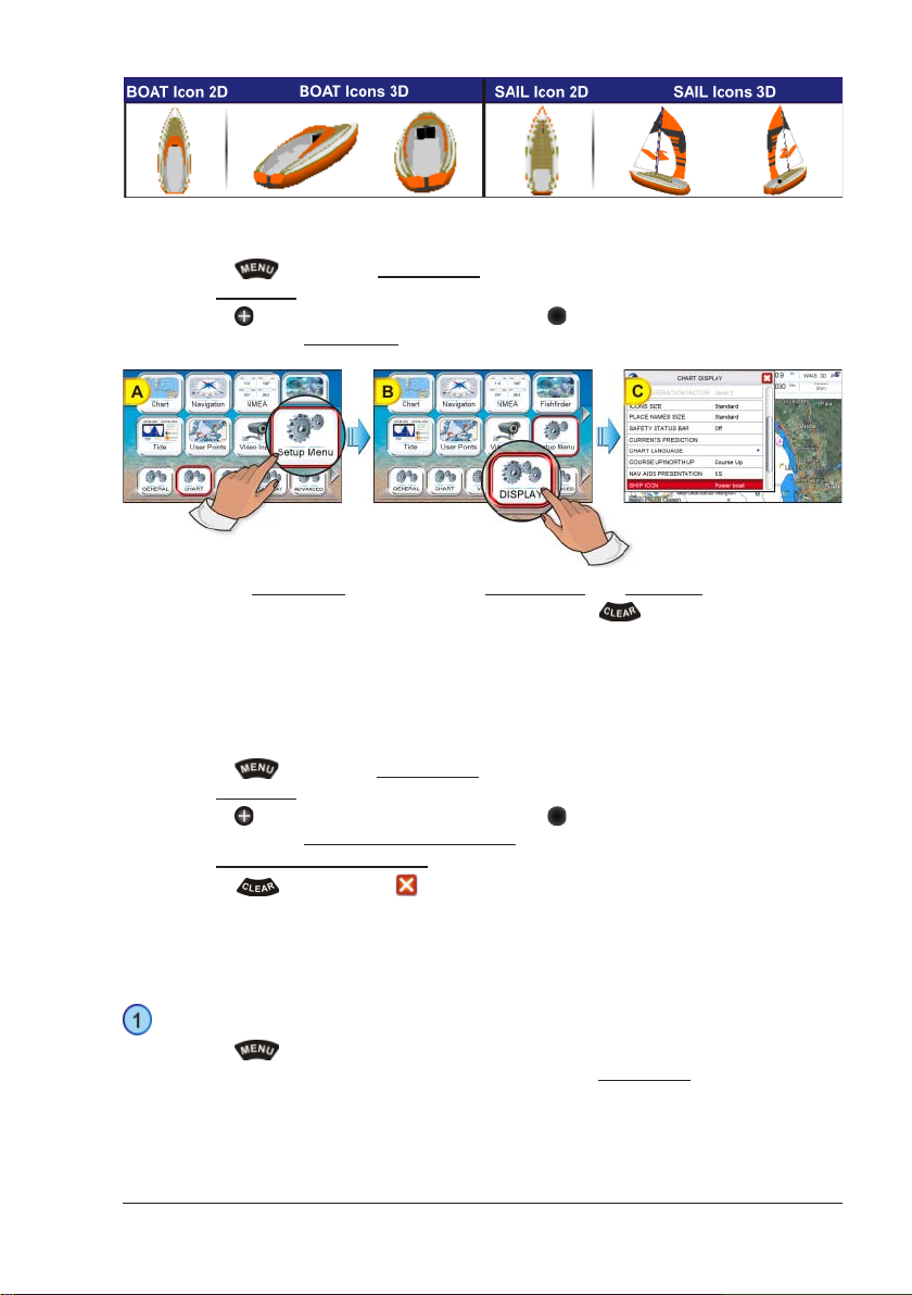
This setting also controls what type of a ship bow is displayed on the Highway page. The
default setting is Power boat. To select the Ship Icon you want follow the procedure:
1. Press the
2. Tap on
3. Move the
the scroll bar until
4. Tapping on SHIP ICON selects between Power boat and Sail boat.
5. When the item you want has been selected, press the
key, tap on Setup Menu (see A).
DISPLAY (see B). The Chart Display menu appears.
ShuttlePoint Knob down or turn the Rotary Knob or touch underneath
SHIP ICON is selected (see C).
key to exit from menu.
Selecting Course Up/North Up
The default selection is Course Up: the top of the Chart Page orientated so it always shows
the area ahead of the direction your vessel is travelling. Also it is possible to select North
Up: the chart is shown with North toward the top of the display.
1. Press the
2. Tap on
3. Move the
the scroll bar until
4. Tap on
5. Press the
key, tap on Setup Menu.
DISPLAY. The Chart Display menu appears.
ShuttlePoint Knob down or turn the Rotary Knob or touch underneath
COURSE UP/NORTH UP is selected.
COURSE UP/NORTH UP to toggle to the desired selection.
key or tap on to save the selection.
Pages Selection
There are three methods to change a page:
From Main Menu
1. Press the
Tap on the desired Page icon (in the following example
Desktop icons appears.
CPN700i and CPN1010i Multimedia Chart Plotters Page 29
key, the Main Menu appears.
Navigation, see A), the related
Page 28
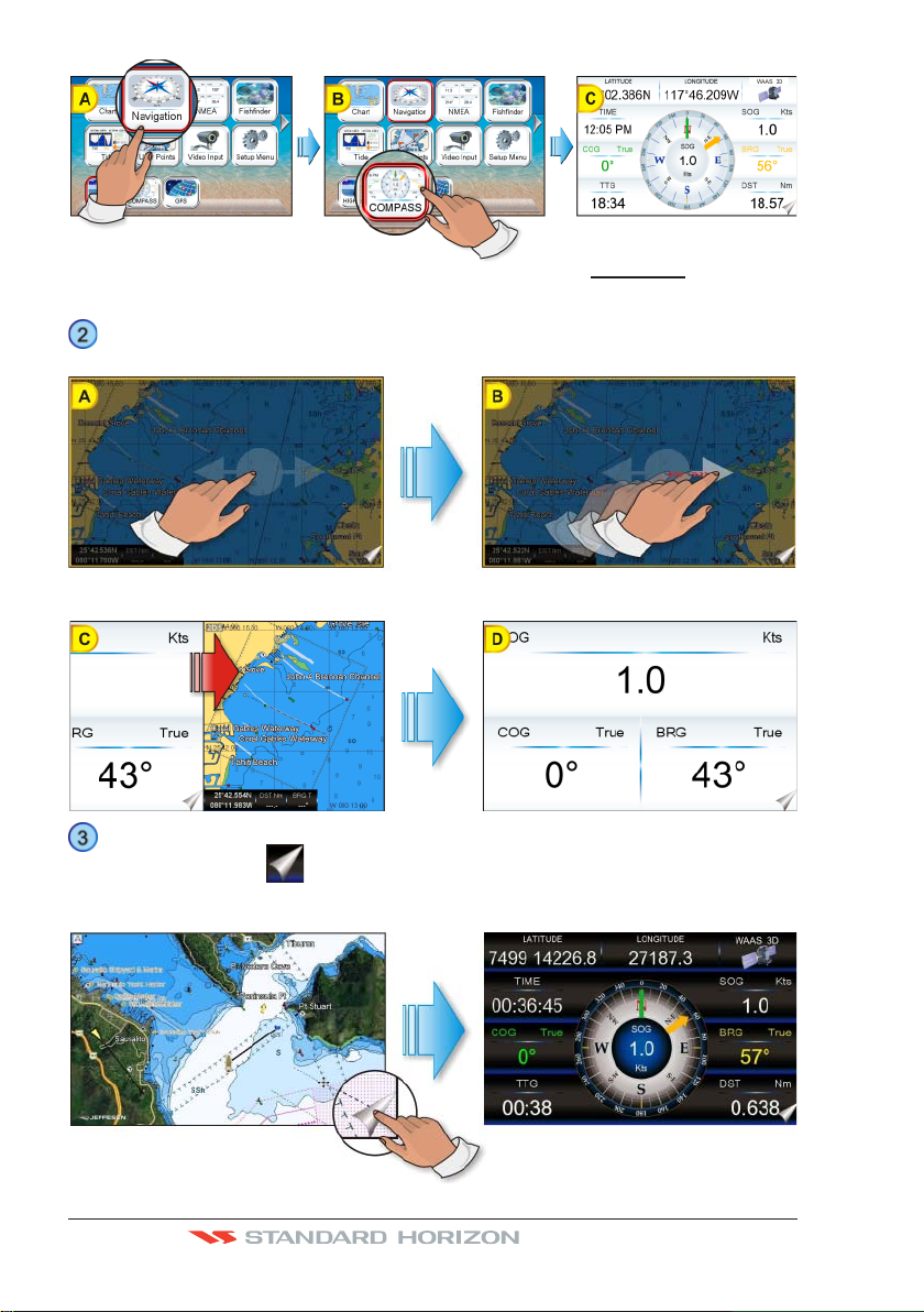
2. Tap on the desired Desktop icon (in the example above COMPASS, see B). The
Compass page appears (see C).
Sweep
1. Press and hold a finger on the display until a double arrow icon is shown (see A).
2. Without removing your finger, slide it to the left or to the right until the arrow turns white
(see B), then remove your finger from the display to change to another page (see C and D).
Page Change Icon
The Page Change Icon
is displayed on every page and it is used for two actions:
· Single tap: changes to the next page. In the example below a single tap on the Page
Change Icon changes to the Compass page.
Page 30 Owner’s Manual
Page 29
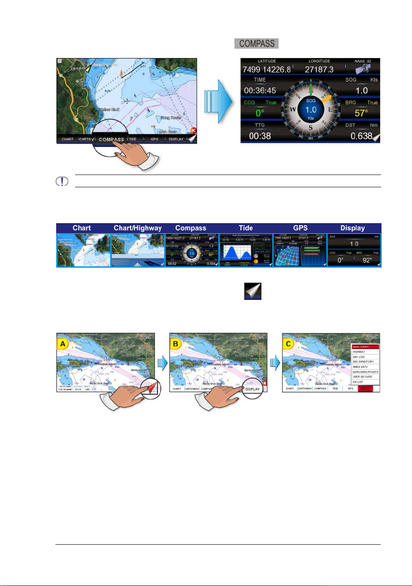
· Long press: shows the page Soft Keys. To change the page, tap on the desired Soft
Key, refer to the image below: tap on the
Compass page.
The pages defined on the Soft Keys are used to define the page change cycle.
Soft Key to change to the
Assigning Page Soft Keys
The default pages are:
The page Soft Keys can be individually customized from the default pages:
1. To change, press and hold the Page Change Key
then remove your finger.
2. Press and hold the page Soft Key you want to customize (see B). A popup window will
be shown with the available pages (see C).
(see A) until Soft Keys are shown,
3. Touch the desired page to select and assign the page to the Soft Key.
Time Setup
The time information supplied by the GPS satellites is in Universal Time Coordinates (UTC or
Greenwich Mean Time). To change the CPN Series Chart Plotter to read the correct time, first you
must figure out the offset and if it is Daylight Saving Time. For example on the West coast of the
United States or Pacific Standard Time the offset needed would be –08:00 or –07:00 for Daylight
Saving Time, Eastern Standard Time –05:00 or –04:00 for Daylight Saving Time. The Time Setup
menu allows you to enter a time zone offset for your location, selection to automatically adjust the
time for Daylight Saving and to configure the time in 12 or 24 hour formats.
CPN700i and CPN1010i Multimedia Chart Plotters Page 31
Page 30
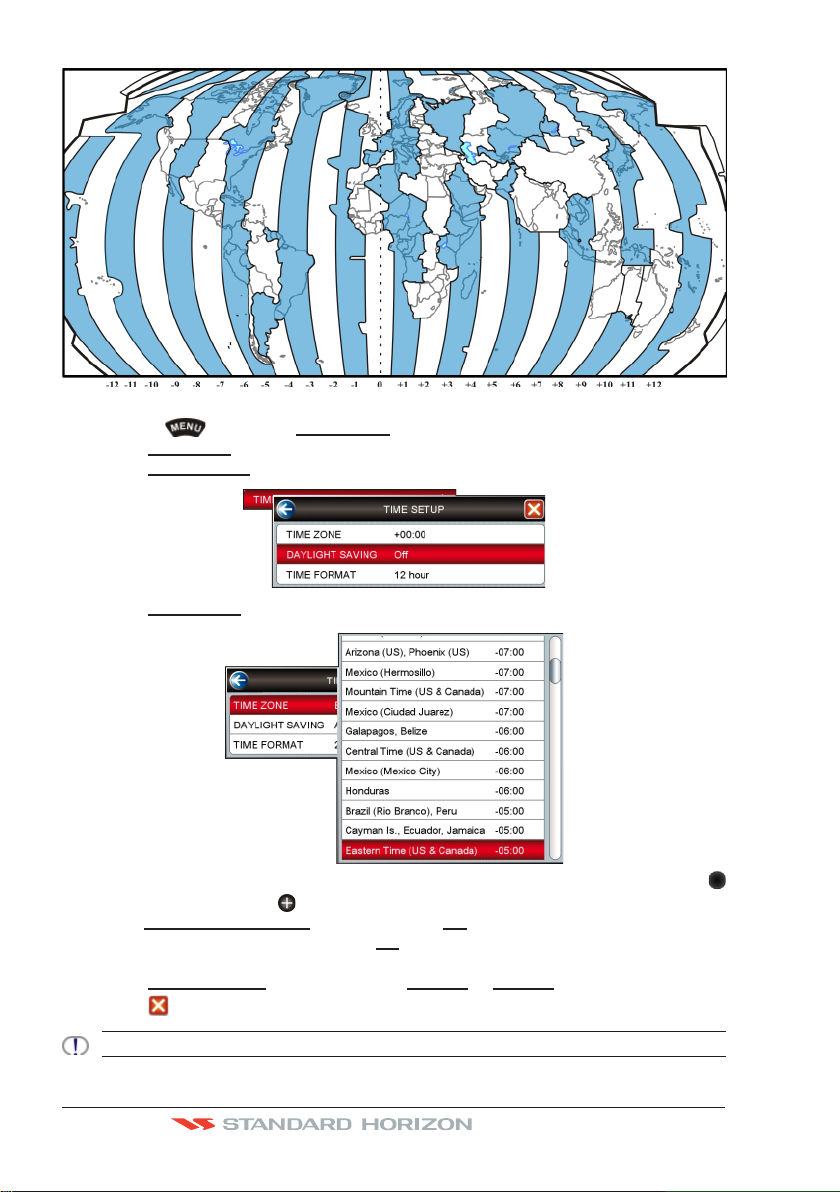
1. Press the key, tap on Setup Menu.
2. Tap on
3. Tap on
GENERAL. The General Setup menu appears.
TIME SETUP. The Time Setup menu appears.
4. Tap on TIME ZONE.
5. Look at the table and find the time zone for your area. Tap under the bar (rotate the
Rotary Knob or move the ShuttlePoint Knob) to select the desired zone and tap on it.
6. Tap on
DAYLIGHT SAVINGS to toggle between Off (select Off when your location does
not recognize Daylight Saving Time) or
On (select On to manually turn Daylight Saving
Time On. This is the default selection).
7. Tap on
8. Tap on
TIME FORMAT to toggle between 12 hour or 24 hour (military) format.
to exit the menu and show the last selected page.
By setting the time in the steps above, the time shown on the Tide page is automatically set up.
Page 32 Owner’s Manual
Page 31

Selecting Coordinate System
GPS Coordinates may be changed to show Latitude/Longitude (default ddd.mm.mmm),
Loran TDs or UTM. To change the Coordinate System, follow the procedure below:
1. Press the
2. Tap on
3. Tap on
4. Tap on
key, tap on Setup Menu.
ADVANCED. The Advanced Setup menu appears.
NAVIGATE. The Navigate menu appears.
COORDINATE SYSTEM.
5. Tap on the desired coordinate type.
6. Press the
key 3 times to show the last selected page.
Loran TD
1. Press the key, tap on Setup Menu.
2. Tap on
3. Tap on
4. Tap on
5. Tap on
ADVANCED. The Advanced Setup menu appears.
NAVIGATE. The Navigate menu appears.
COORDINATE SYSTEM.
TD.
6. Tap on CHAIN and turn the Rotary Knob to select the Chain then tap on the number.
7. Tap on
8. Press the
PAIR and turn the Rotary Knob to select the Pair then tap on the letters.
key 3 times to show the last selected page.
If the TD numbers are not show correctly on the Chart Page, the Pair letters may be backwards. Reversing
the two letters usually solves this issue. Example Y/Z change to Z/Y.
Changing the Display Color
The CPN Series Chart Plotter has preprogrammed settings allowing you to customize the
look of the pages. The default is Normal.
1. Press the
2. Tap on
3. Tap on
Normal, Classic, NOAA, Night and Sunlight.
CPN700i and CPN1010i Multimedia Chart Plotters Page 33
key, tap on Setup Menu.
GENERAL. The General Setup menu appears.
DISPLAY COLOR. A popup window will be shown with the available options
Page 32

4. Tap on the desired selection.
5. Tap on
In the pictures A and B you can see examples of charts and Compass page with the Display
Color set to Normal.
In the pictures C and D you can see the same examples with the Display Color set to
Sunlight.
to exit the menu and show the last selected page.
Selecting Language
To ease operation in different countries, the CPN Series Chart Plotters include translations
in the following 16 Languages:
· English · Italian · French
· German · Spanish · Norwegian
· Swedish · Portuguese · Chinese (Traditional)
· Danish · Dutch · Greek
· Finnish · Russian · Chinese (Simplified)
· Japanese
Multilanguage will display the digitized data in the charts as long as the source paper chart
was done in the national language. For instance, if a Chinese chart is done in English, the
digitized data will only display in English. However, if it was done in Chinese, then the
digitized data can display Chinese or English. The translations are included in menus, data
pages, warning/alarm messages, full/quick info, list of objects found by find/nearest
function, and on charts (such as place’s names and buoy’s names and so on).
To select the language you want:
Page 34 Owner’s Manual
Page 33

1. Press the key, tap on Setup Menu.
2. Tap on
3. Move the
4. Tap on
GENERAL. The General Setup menu appears.
ShuttlePoint Knob down or turn the Rotary Knob or touch underneath
the scroll bar until
LANGUAGE is selected.
LANGUAGE. Another popup window will be shown with the available
languages.
To see additional languages, tap under bar or move the ShuttlePoint Knob down or turn the Rotary
Knob.
5. Tap on the language you want.
6. Tap on
If the selected language is not available on cartographic data, English is used.
to exit the menu and show the last selected page.
Chart Control Icon
When the Chart Page is selected a transparent icon (see A) is shown. This icon allows
control of Zooming, Tilting, Rotating and controlling the Transparency and Exaggeration
1
when optional C-MAP charts are used.
Factor
1
Available only in 3D mode.
Tap on the centre of the Chart Control Icon (see B) it is possible to select the desired icon
among the available ones, see the table below:
CPN700i and CPN1010i Multimedia Chart Plotters Page 35
Page 34

The default setting of the Chart Control Icon is Shown Permanent, however this may be
changed by the procedure below:
1. Press the
2. Tap on
3. Turn the
4. Tap on
5. Tap on
6. The menu shows
key, tap on Setup Menu.
GENERAL. The General Setup menu appears.
Rotary Knob until CHART CONTROL ICON is highlighted.
CHART CONTROL ICON.
SHOWN.
Off, 2 Seconds, 5 Seconds, 10 Seconds and Permanent. Tap on
the item you want.
7. Press the
key repeatedly until the menu disappears.
The default place of the Chart Control Icon is on the right top side, however this may be
changed by the procedure below:
1. Press the
2. Tap on
3. Turn the
4. Tap on
5. Tapping on
6. When the item you want has been selected, press the
key, tap on Setup Menu.
GENERAL. The General Setup menu appears.
Rotary Knob until CHART CONTROL ICON is highlighted.
CHART CONTROL ICON.
LOCATION selects between Left and Right.
key repeatedly until the
menu disappears.
SETTINGS IN GENERAL SETUP MENU
The General Setup menu has other selections that allow you to customize the display. All
selections are listed in the following table:
TIME SETUP Selects the Time Zone offset, enable or disable Daylight Savings time, selects the
DATE FORMAT Selects the Date format among MM-DD-YY (default), DD-MM-YY or YY-MM-DD.
PAGE SWEEP Selects among Animated (default), Normal and Off the swipe control to change page.
KEYPAD BEEP Allows the beep produced when a key is pressed to be turned On (default) or Off.
SHUTTLE POINT ENTER ShuttlePoint Knob press is user selectable. When set to On (default), pressing the
UNITS OF MEASURE Units of Measure can be selected for Distance, Speed, Depth, Altitude and Temperature:
DISPLAY COLOR Changes the background colors to enhance the visibility of the screen depending on the
CURSOR SPEED Selects the speed among Low, Medium (default) and High for the cursor in the CHART
Time Format and switch between 12 or 24 hours time format.
ShuttlePoint Knob in the center is equal to confirm action. When set to Off, pressing the
ShuttlePoint Knob in the center will not produce any effect.
Distance: selections are Nm (Nautical Miles), Sm (Statue Miles), Km (Kilometers), Nm+Ft, Nm+Mt. Note when “Nm+Ft” is selected if the distance is less
than 1.0 Nm, it turns to Feet. When “Nm+Mt” is selected if the distance is less
than 1.0 Nm, it turns to Meters.
Speed: selections are Kts (knots), MPH (miles per hour), Kmh (kilometer per
hour).
Depth: selections are Ft (feet), FM (fathoms) and Mt (meters).
Altitude: selections are Ft (feet) and Mt (meters).
Temperature: selections are F (Fahrenheit) and C (Celsius).
surrounding light conditions. Normal (default) is recommended when the CPN Series
Chart Plotter is not exposed to the direct sunlight. When this mode is set the charts are
displayed in order to use colors as similar as possible to ones used in the original paper
charts. Night is recommended when the environment is dark in order to reduce the glare
of the display. Sunlight is designed to enhance the visibility of the screen when the CPN
Series Chart Plotter is exposed to sunlight. Classic uses vivid chart colors presentation.
NOAA allows setting NOAA paper chart colors presentation.
page and within the MENU.
Page 36 Owner’s Manual
Page 35

MEASURE DISTANCE When this function is On, tap (or move the ShuttlePoint Knob) on a location where you
want to start measuring a distance (see A). Tap on a second location where you want to
finish measuring a distance. A line appears between the Start and Finish points and a
popup window will be shown indicating the distance and bearing from the Start and Finish
points (see B). Tap on the
is Off.
Soft Key to delete both points. The default setting
CHART PAGE WINDOW Allows selection of data windows. Selections are None, General, 1 Line Small, 1 Line
LANGUAGE Allows changing the language for menus and data screens. English is the default.
AUTO INFO When the cursor is moved over a buoy, Mark or other item a popup window will show
HOME MODE REVERT Sets the timeout (among 10 sec, 30 sec, 1 min (default), 2 mins, 5 mins and Off) after
CURSOR WINDOW By default when the cursor is moved on the chart a window is shown with the Lat/Lon
CHART CONTROL ICON Opens a menu with two items:
BUILT-IN CHARTS AVAILABLE ONLY FOR USA Enables (On) or disables (Off) the Built-In Charts. The
Large and 2 Lines Small (default). The data windows may be customized (see
“Customizing Data Windows” paragraph in “Main Menu” section) and may be collapsed
or shown to show more or less chart area (see “Collapsing Data Windows” paragraph in
“Main Menu” section).
information of the item. This menu item allows the window to be turned Off, On Points
(default) or On All.
which the CPN Series Chart Plotter goes back from Cursor Mode to Home Mode.
Distance and Bearing from the vessels location to the cursor. This selection allows the
window to be turned On (default) or Off. It appears only on the Chart pages (Single, Dual
and Chart/Highway). The Cursor Window is automatically disabled when General is set
in Chart Page Window option.
SHOWN: the chart control touchscreen icon can be permanently shown (default) or it
can be shown for a while (timeout) when the keyboard is touched. Select the timeout
among 2 sec, 5 sec, 10 sec, Permanent and Off.
LOCATION: the chart control touchscreen icon can be shown on the Right (default) or
Left top side of the screen.
default is On.
CARTOGRAPHY OVERVIEW
BUILT-IN CHARTS --- AVAILABLE ONLY FOR USA
The CPN Series Chart Plotters have Built-In Charts for coastal navigation with the following
characteristics (refer to the following image for coverage area of Built-In Charts).
· Coverage: USA including Alaska, Hawaii and Great Lakes, Canada, Bahamas,
Caribbean, Cuba, Mexico, Puerto Rico, and Central America. Fresh water coverage is
not included. Detailed coverage and Fresh waters charts are available from Jeppesen.
· Depth contours and Spot Soundings to 66 Feet (20 meters) on lower scale charts and
CPN700i and CPN1010i Multimedia Chart Plotters Page 37
Page 36

33 Feet (10 meters) on higher scale charts.
· Port Info: basic information for Marinas and the list of services symbols.
· Selectable Tide Page showing Tidal information, moon and sun rise and set times.
· All Nav-Aids with icon and description
· 2D standard nautical vector cartography
· Guardian Alarm is not available while using only the Built-In Charts
To use all Marina information along with 2D and 3D Raster and satellite imagery a C-MAP
4D CARD must be purchased and installed.
Updating Built-In Charts
The Built-In Charts can be updated by purchasing a Chart Update Card from C-MAP USA
at (800) 424-2627. This Chart Update Card may be used ONE time to update the charts
in a CPN Series Chart Plotter. After the updating, the Chart Update Card will not update
other CPN Series Chart Plotters. To purchase the Chart Update Card you must supply the
UNIT ID code. This code is found on the About Page, refer to the procedure below:
1. Press the
2. Tap on the right arrow next to ADVANCED Desktop icon two times to display
and tap on it.
3. The About Page appears on the screen, refer to the picture below:
Page 38 Owner’s Manual
key, tap on Setup Menu.
ABOUT
Page 37

The Chart Update Card will be use ONLY on the CPN Series Chart Plotter with that UNIT
ID code.
After purchasing the Chart Update Card, follow the procedure to update the charts.
1. Press the
PWR key to turn the CPN Series Chart Plotter Off.
2. Insert the Chart Update Card into the slot.
3. Press and hold the PWR key to turn the CPN Series Chart Plotter On.
4. The package update window appears (see A). The CPN Series Chart Plotter checks the
integrity of the Installation Package present on the Chart Update Card. This operation
might require several minutes (if you want to abort the installation tap on
).
At the end of the checking, the package update window shows the following data (see B):
The touchscreen key is now selected (it appears with blue frame).
If case of error message, press the PWR key to turn the CPN Series Chart Plotter Off and then follow
steps 3-4 again. If the CPN Series Chart Plotter shows a error message again, contact C-MAP USA at
(800) 424-2627 for assistance.
5. Tap on to start installation (or tap on to abort).
6. The installation process begins.
Pay attention: do not turn the CPN Series Chart Plotter
Off during installation. The installation status appears in the two progress bars on the
bottom of the package update window (see C):
CPN700i and CPN1010i Multimedia Chart Plotters Page 39
Page 38

7. At the end of the installation process, the Start Up Screen is shown.
8. To complete the Built-In Charts update procedure, press the
PWR key to turn the
CPN Series Chart Plotter Off and remove the Chart Update Card from the slot.
9. Then press and hold the
PWR key to turn the CPN Series Chart Plotter On: the Built-
In Charts are updated and ready to use.
In case of error messages please refer to System Update Error Messages paragraph.
C-MAP 4D
DIGITAL NAVIGATION CHARTS THAT GROW WITH YOUR BOATING NEEDS
To learn more go to http://www.jeppesen.com/main/corporate/no-wpr/c-map-4d/index.jsp
C-MAP 4D is the only maritime chart plotting solution that lets you completely customize
your digital navigation charts and has the capability of adding new marine chart data as it
becomes available.
First, choose either the MAX or Full 4D content on your cartridge. Should you start out with
MAX and decide at a later date to upgrade to the full 4D content, simply use the same
cartridge to purchase and unlock the additional technology. C-MAP 4D allows you to unlock
or add Value Added Data (to either MAX or 4D content) as they become available.
General Features
· ISO Certification: electronic chart production process with quality certification ISO 9001.
· Official data source: data based on use of official data sources Hydrographic Offices
Release.
· Detailed World Background: worldwide background chart with details, satellite and
3D data on selected zoom ranges.
Data Features
· Search & Find: quickly locates chart contents and objects - Tide Station, Port Info, Port
by Name, Wrecks, Obstructions, Lake name/info, POI.
· Port Info: searchable data base of service in Ports.
· Object Info: moving cursor over object to show restricted area details and related
information.
· Quick Info: moving cursor over Wrecks, shoals, Nav-Aids to show restricted area
details and related information and object to show details.
· True-Type Font: improves text on chart for optimal reading.
Presentation Features
· Clear View: advanced legibility techniques providing more chart data on the screen
· Clear Info: sophisticated "Human Dictionary" to translate Nav-Aid abbreviations found
on paper charts.
Page 40 Owner’s Manual
Page 39

· Enhanced Mixing Levels: seamless data presentation.
C-MAP 4D: MAX Content
· Nav-Aids: detailed information on Navigational Aids, including name, color, informa-
tion on frequency, range of the light, etc.
· Guardian Alarm: the Guardian Alarm is a user defined area in front of your vessel to
alert you while navigating of possible obstacles on the chart. When activated, Guardian
Alarm performs an automatic forward-scanning check for obstacles.
· Safety Status Bar: a status bar with six boxes to show the status of certain functions.
Any warning or alarm condition is identified by the red color to indicate possible risk.
· Safe Route Check: sophisticated function that checks for dangerous objects along
your navigation route.
· C-Marina Port Database: complete port and marina charts with detail.
· Multilanguage capability: allows showing language of your choice in using proper
character set for Asian and other countries.
· Tides Preview: allows viewing of current, future and past tide cycles from worldwide
Tide Stations database.
· Dynamic Currents: current arrows showing speed and direction of current, future and
past currents.
· Photos & Diagrams: high definition pictures of ports, piers, bridge diagrams and
Nav-Aids.
· Depths & Land Elevation: color shading of sea depth and land altitude for improved
chart appearance.
· Perspective view: for a bird’s-eye view of your navigation area.
· Points Of Interest (POIs) and road mapping: searchable data base of detailed
information that include facilities and services in ports and surrounding areas.
C-MAP 4D: FULL 4D Content
All above and in addition:
· 3 Dimensional Chart View: the world has three dimensions. When you add the 4th
dimension of time – meaning consistent, periodic updates – you combine the most
detailed 3D height and depth worldwide database with a continuous update process to
give you a personalized navigation experience with up-to-date data for safe navigation.
· Satellite Images with 2D and 3D overlay: C-MAP 4D includes a navigational
perspective with high-resolution coastal imagery overlaid on the most accurate and upto-date vector data, plus thousands of extraordinary photos for the most popular
marinas and areas of interest.
· Digital Raster Chart: with raster charts, you have an additional reference source for
navigational awareness. Get “at-a-glance” information using the nautical paper charts
overlaid on 2D and 3D views on multi-dimensional shaded relief to have a new visual
experience.
· Easy Routing: automatic creation of a Route. Enter start and end points along with
specific boat parameters and automatically receive Waypoints of the shortest Route;
highlights potential hazards and displays varying levels of alerts for each segment of
the route, allows you to manually adjust the route.
CPN700i and CPN1010i Multimedia Chart Plotters Page 41
Page 40

C-MAP 4D: Value Added Data
New additional data or service to standard cartography available (High Resolution Bathym-
etry, weather, etc). You can enable or disable the display of the category as a whole or of
each individual.
· High Resolution Bathy charts & Spot Soundings: Data Base with high resolution
bathy information for an extraordinary view of the seabed depth.
VALUE ADDED DATA MENU
The VAD Menu is a multiple options menu with the information present on the optional
C-MAP 4D CARD. Value Added Data are divided into categories; inside each category there
is a set of objects. Some of the VAD categories are free and some others have to be
purchased. You can enable or disable the display of the category as a whole or of each
individual object inside the category.
· each category has a separate submenu
· each category has a On/Off/Custom settings available:
·On switches the display of all object in the category on
· Off switches it off
· Custom allows to set each object separately in the submenu
To select the VAD menu follow the procedure:
1. Press the
2. Tap on
key, tap on Setup Menu.
VAD. The VAD menu appears on the screen.
REMOVING A SD CARD
To safely remove the SD CARD follow the procedure:
1. Press the
2. Tap on the right arrow next to ADVANCED Desktop icon two times to display
and tap on it. The About Page appears on the screen.
3. Tap anywhere in the About Page to display Soft Keys on the bottom of the page.
4. Tap on the
5. Tap on
6. Open the door, gently remove the SD CARD from the slot.
7. Press the
Page 42 Owner’s Manual
key, tap on Setup Menu.
ABOUT
Soft Key.
in the popup window, then on on the next window.
key to exit.
Page 41

USING FIND SERVICES
This function finds only the cartographic objects which are been set to visible (On) in the menu.
It is possible to search the Built-In Charts1 and the optional C-MAP 4D SD CARD for Port
Services, Ports, Tide Stations, Wrecks, Obstructions, Points Of Interest, Lakes, User
Points, GPS Coordinates or Information on any point on the Chart.
1
ONLY FOR USA.
The amount of information might be due to the optional C-MAP 4D charts installed.
1. Press the key, tap on Chart.
2. Tap on
PORT SERVICES
This feature is used to locate Port Services nearest the position of your vessel. The following
table shows a list of some of the available Port Services and icons shown on the Chart Page:
FIND. The Find Services & More menu appears.
1. Press the key, tap on Chart.
2. Tap on
3. Tap on
FIND. The Find Services & More menu appears.
PORT SERVICES. A popup window will be shown with a list of different Port
Services (see A).
4. Move the
CPN700i and CPN1010i Multimedia Chart Plotters Page 43
ShuttlePoint Knob or touch the screen to highlight the desired type of
Page 42

service and tap on . Another popup window will appear displaying the
distance and position of the Port Services closest to your location (see B). Otherwise
tap on
5. Use the ShuttlePoint Knob to highlight the desired Port Service and tap on
6. Press the key to show the actual position of the service on the Chart Page.
7. Press the
to exit.
. This will show information about the service (see C). Otherwise tap on
to exit.
key again at any time to return your cursor to your vessel’s position.
PORT
A Port is represented with a on the Chart Page. This feature is used to locate the 20
nearest Ports to the position of your vessel.
1. Press the
2. Tap on
3. Tap on
4. Move the
5. Tap on
to search the Port by inserting the name. Tap on to exit from Port function.
6. Press the key at any time to return your cursor to your vessel’s position.
Page 44 Owner’s Manual
key, tap on Chart.
FIND. The Find Services & More menu appears.
PORT. A popup window will be shown with a list of nearest Ports (see A).
ShuttlePoint Knob to highlight the desired Port and tap on it.
to show the details of the Port (see B), otherwise tap on
Page 43

TIDE STATIONS
A Tide Station is represented with a on the Chart Page. This feature is used to locate
the 20 nearest Tide Stations to the position of your vessel. Once a Tide Station is selected
the Tide Graph can be used to determine Tide height and draught of the Tide based on
a user-specified time.
1. Press the
2. Tap on
3. Tap on
Stations (see A).
4. Move the
5. Tap on
6. Press the
Refer to the image (B) above. Moving the ShuttlePoint Knob left and right controls the
Tide Prediction time
Vessel Draft value
key, tap on Chart.
FIND. The Find Services & More menu appears.
TIDE STATIONS. A popup window will be shown with a list of nearest Tide
ShuttlePoint Knob to highlight the desired Tide Station and tap on it.
to show the detail of the Tide Station (see B).
key at any time to return your cursor to your vessel’s position.
and moving the ShuttlePoint Knob up or down controls the
.
The Local Offset matches the Time Offset entered in the Time Setup menu.
Changing the day
1. Tap anywhere on the Tide page.
2. Tap on the
3. Enter the date using the touchscreen keyboard. When finished tap on
keyboard disappears.
Soft Key (see C).
, the
Changing Tide Station
1. Tap anywhere on the Tide page.
2. Tap on the
3. Tap on the desired Tide Station in the menu (see D).
4. Tap on
menu.
CPN700i and CPN1010i Multimedia Chart Plotters Page 45
Soft Key (see C).
to show the new Tide information or tap on to exit the
Page 44

WRECKS
This feature is used to locate the 20 nearest Wrecks to the position of your vessel. A Wreck
is represented with an icon on the chart, see the following table:
1. Press the key, tap on Chart.
2. Tap on
3. Tap on
4. Move the
5. Tap on
6. Press the
FIND. The Find Services & More menu appears.
WRECKS. A popup window will be shown with a list of nearest Wrecks (see A).
ShuttlePoint Knob to highlight the desired Wreck or tap on it.
to show the location of the Wreck (see B).
key 2 times to revert to your vessel’s position.
OBSTRUCTIONS
This feature is used to locate the 20 nearest Obstructions to the position of your vessel.
An Obstruction is represented with an icon on the chart, see the following table:
1. Press the key, tap on Chart.
Page 46 Owner’s Manual
Page 45

2. Tap on FIND. The Find Services & More menu appears.
3. Tap on
4. Move the
5. Tap on
6. Press the key 2 times to revert to your vessel’s position.
OBSTRUCTIONS. A window is shown with a list of nearest Obstructions (see A).
ShuttlePoint Knob to highlight the desired Obstruction or tap on it.
to show the location of the Obstruction (see B).
LAKES INFORMATIONS
A Lake Info is represented with a on the Chart Page. This feature is used to find
information on the 20 closest Lakes near the position of your vessel.
1. Press the
2. Tap on
3. Tap on
4. Tap on the desired object and tap on
LAKES INFORMATION. A window is shown with a list of Outdoor Recreational
Area objects (see A).
distance and position of the Lakes closest to your location (see B).
key, tap on Chart.
FIND. The Find Services & More menu appears.
. A window appears displaying the
5. Move the ShuttlePoint Knob to highlight the desired Lake or tap on it.
6. Tap on
7. Press the key 2 times to revert to your vessel’s position.
CPN700i and CPN1010i Multimedia Chart Plotters Page 47
to show the location of the Lake (see C).
Page 46

QUICK AND FULL INFO ON LAKES
Upon viewing the chart of a lake, you can tap on the Lake Info icon (see A) to query the
available information immediately displayed with many details. When the cursor is placed
over this icon (and the Auto Info option is allowed) the Quick Info window appears: the icons
of the available services are shown (see B).
To see the "Fishing" object tap on the Soft Key (see C). Tap on the Soft
Key to obtain the Full Info on Lakes: all available information about the cartographic point
under the cursor will be shown (see D).
LAKES BY NAME
This feature is used to locate Lakes By Name nearest the position of your vessel.
1. Press the
2. Tap on
3. Tap on
LAKES BY NAME. A window will be shown with a list of nearest Lakes (see A).
key, tap on Chart.
FIND. The Find Services & More menu appears.
Now you can browse the list (step a) or enter the Lake name (step b):
a. Browse the list and tap on the desired Lake.
Page 48 Owner’s Manual
Page 47

b. Tap on to enter the desired Lake name. The touchscreen keyboard
appears, it will allow you to enter in the name of the Lake you wish. Insert the desired
name; when finished tap on
appear displaying the distance and position of the Lake. Tap on the desired Lake.
4. Tap on
Soft Key or on the Soft Key to obtain the Full Info on Lakes: all available
information about the cartographic point under the cursor will be shown.
to show the Information on the Lake (see B). Tap on the
, the keyboard disappears. Another window will
POINTS OF INTEREST
This feature is used to locate Points Of Interest nearest the position of your vessel.
1. Press the
2. Tap on
3. Tap on
of Category types (i.e. attractions, emergency, entertainment).
4. Tap on the desired Category. A (Type) popup window will be shown with a list of types
(see A).
5. Tap on the desired Type. A popup window will be shown with a list of nearest Points Of
Interest that fall into the Category and Type you have selected (see B).
key, tap on Chart.
FIND. The Find Services & More menu appears.
POINTS OF INTEREST. A (Category) popup window will be shown with a list
6. Tap on the desired Point Of Interest.
7. Tap on
8. Press the key 2 times to revert to your vessel’s position.
to show the location of the Point Of Interest information (see C).
USER POINTS
This feature is used to search for User Points (Marks and Waypoints you have created
and stored) by name quickly and efficiently.
CPN700i and CPN1010i Multimedia Chart Plotters Page 49
Page 48

1. Press the key, tap on Chart.
2. Tap on
3. Tap on
4. Press the
FIND. The Find Services & More menu appears.
USER POINTS. The touchscreen keyboard appears, it will allow you to enter in
the name of the User Point you wish to locate. Insert the desired name; when finished
tap on
on the Chart Page.
, the keyboard disappears. The screen shows the location of the User Point
key 2 times to revert to your vessel’s position.
COORDINATES
This feature allows you to enter Coordinates (Latitude/Longitude) and view the entered
position on the Chart Page.
1. Press the
2. Tap on
3. Tap on
4. Press the
COORDINATES. The touchscreen keyboard appears, it will allow you to enter
in a specified Latitude and Longitude. Once the Coordinates are entered tap on
the keyboard disappears. The screen shows the desired location on the Chart Page.
key, tap on Chart.
FIND. The Find Services & More menu appears.
key 2 times to revert to your vessel’s position.
INFORMATIONS
This feature allows you to obtain information on any position on the Chart page.
1. Press the
2. Tap on
3. Turn the
4. Tap on
key, tap on Chart.
FIND. The Find Services & More menu appears.
Rotary Knob to select INFORMATION.
INFORMATION to show the page below:
,
The left side of the page contains the Info Tree and the right side contains the expanded
information. While tapping on the left side page moving through the Info Tree, all the
relevant information of the selected object is shown on the right part of the page.
5. Press the
Page 50 Owner’s Manual
key 3 times to exit to the Chart Page.
Page 49

CHART DISPLAY FUNCTIONS
The Chart functions menu can be access using the Main Menu as shown below:
1. Press the
2. Tap on
sections, one related to the 4D functions and another for generic chart display.
4D FUNCTIONS
Chart Window
This function selects the window that will be affected by the 4D related settings (see the
following paragraphs). Each chart window has its own settings so, when Chart Window item
is changed, all relevant settings are update accordingly. The two available selections are
Chart1 (default, applies to Single Chart and to the left chart window in Dual Chart) and Chart2
(applies to the right chart window in Dual Chart).
To activate this function follow the procedure:
1. Press the
2. Tap on
3. Tapping on
4. Once the window is selected the options can be set for that chart. Tap on
menu.
key, tap on Setup Menu (see A).
DISPLAY (see B) . The Chart Display setup appears (see C) divided in two
key, tap on Setup Menu.
DISPLAY. The Chart Display menu appears.
CHART WINDOW selects between Chart1 or Chart2.
to exit from
Display Mode
This function allows to toggle among the (default) 2D (see A) and 3D (see B) modes to
display the chart on the screen:
CPN700i and CPN1010i Multimedia Chart Plotters Page 51
Page 50

To activate this function follow the procedure:
1. Press the
2. Tap on
3. Tapping on
4. When the item you want has been selected, tap on
key, tap on Setup Menu.
DISPLAY. The Chart Display menu appears.
DISPLAY MODE selects between 2D or 3D.
to exit from menu.
Overlay
This function allows to overlay Satellite (default) image (see B), Raster Charts (see C),
Vector (see A) or Chart Shading (see D) for background charts.
Chart Shading is available only in Display Mode 2D.
To activate this function follow the procedure:
1. Press the
2. Tap on
3. Tap on
4. The menu shows
you want.
5. Tap on
key, tap on Setup Menu.
DISPLAY. The Chart Display menu appears.
OVERLAY.
Satellite, Raster Charts, Chart Shading or Vector. Tap on the item
to exit to the Chart Page.
Overlay Mode
This function sets the overlay area of Satellite and Raster images. To activate this function
follow the procedure:
1. Press the
2. Tap on
3. Tap on
4. The menu shows
Page 52 Owner’s Manual
key, tap on Setup Menu.
DISPLAY. The Chart Display menu appears.
OVERLAY MODE.
On Land (default), On Sea and On All. Tap on the item you want.
Page 51

5. Tap on to exit to the Chart Page.
Transparency
This function sets the transparency value between the vector chart and the layer over it
(raster or satellite). To activate this function follow the procedure:
1. Press the
2. Tap on
3. Tap on
4. A new window appears to insert the desired value (0 - 100). Tap on or to reach
the desired value, then tap on
the
Rotary Knob to cycle between bar, or .
Available only if Overlay is Satellite or Raster Chart.
key, tap on Setup Menu.
DISPLAY. The Chart Display menu appears.
TRANSPARENCY.
(tap on otherwise). You can use
3D Exaggeration Factor
This function vertically stretches the land elevations and depths. It sets the 3D Exaggeration
Factor among 5 levels. To activate this function follow the procedure:
1. Press the
2. Tap on
3. Tap on
4. The menu shows
5. Tap on
key, tap on Setup Menu.
DISPLAY. The Chart Display menu appears.
3D EXAGGERATION FACTOR.
Level1, Level2, Level3, Level4 and Level5. Tap on the item you want.
to exit to the Chart Page.
Available only in 3D mode.
GENERAL CHART DISPLAY FUNCTIONS
Icon Size
It is possible to set the size of all icons drawn on the charts, selecting between Standard
(default) and Large size. To activate this function follow the procedure:
1. Press the
2. Tap on
3. Tapping on
4. When the item you want has been selected, tap on
CPN700i and CPN1010i Multimedia Chart Plotters Page 53
key, tap on Setup Menu.
DISPLAY. The Chart Display menu appears.
ICONS SIZE selects between Standard or Large.
to exit from menu.
Page 52

Place Name Size
It is possible to set the size of all names drawn on the charts, selecting between default
Standard (see A), Medium (see B) and Large (see C) size.
To activate this function follow the procedure:
1. Press the
2. Tap on
3. Tap on
4. The menu shows
5. Tap on
key, tap on Setup Menu.
DISPLAY. The Chart Display menu appears.
PLACE NAMES SIZE.
Standard, Medium or Large. Tap on the item you want.
to exit to the Chart Page.
Safety Status Bar (DSI - Data Safety Indicator)
When the Safety Status Bar is enabled, a status bar with six boxes shows the status of
certain functions. Any warning or alarm condition is identified by the red color to indicate
possible risk.
Page 54 Owner’s Manual
Page 53

To activate this function follow the procedure:
1. Press the
2. Tap on
3. Tap on
4. The menu now shows the following selections:
On: The Safety Status Bar is shown
Off: The Safety Status Bar is not shown
Icon: In this mode the Safety Status Bar is not shown, rather a Warning Icon
will be shown in the top right corner on the chart page when an alarm condition is
met.
5. Tap on the desired selection.
6. Tap on
key, tap on Setup Menu.
DISPLAY. The Chart Display menu appears.
SAFETY STATUS BAR.
to exit to the Chart Page.
Currents Prediction
This feature only operates in areas where tidal buoys are present and when the CPN Series
Chart Plotter has a GPS fix. Tidal stream arrows are shown on the charts, indicating the
direction and strength of the Tide:
CPN700i and CPN1010i Multimedia Chart Plotters Page 55
Page 54

The color of the arrow denotes the strength of the current as follows:
When the CPN Series Chart Plotter receives a valid position fix, the Tide icons are shown
on the charts on the basis of the current date and time: the screen displays and changes
arrows as date/time changes.
It is possible to see the variation of the Tidal arrows on the selected area at any given time.
To activate this function follow the procedure:
1. Press the
2. Tap on
3. Turn the
4. Tap on
5. Tap on the
key, tap on Setup Menu.
DISPLAY. The Chart Display menu appears.
Rotary Knob to select CURRENTS PREDICTION.
CURRENTS PREDICTION.
Soft Key to set the date and time manually, and on the
/ Soft Keys to increase/decrease time; tap on the Soft Key to exit.
Chart Language
The CPN Series Chart Plotter may be customized to show the local language of the chart.
To select the Chart Language you want:
1. Press the
2. Tap on
3. Turn the
4. Tap on
described in the table.
Language : Allows setting the language to display chart information. The language is chosen among the list
Mode : Defines how objects are translated. Selections are:
5. Tap on to exit to the Chart Page.
key, tap on Setup Menu.
DISPLAY. The Chart Display menu appears.
Rotary Knob to select CHART LANGUAGE.
CHART LANGUAGE. A new window will appear with available functions
of languages available on the cartographic data (data cartridge or embedded charts).
Off : Enables the language chosen in the Language menu above. If the selected
language is not present on the objects information, English is used.
English: Always uses English.
Local : Uses the Local language present on C-MAP B
language is available, English is used.
Y JEPPESEN SD CARD. If no Local
a. When the Chart Language is changed, the following settings are automatically selected: MODE is set
to Off and Chart Language is set to your selection.
b. If the SD CARD is removed or changed, the Chart Language should be confirmed and changed if
necessary.
Course Up/North Up
The default selection is Course Up: the top of the Chart Page oriented so it will always show
the area ahead of the direction your vessel is travelling. Also it is possible to select North
Up: the chart is shown with North upwards.
Page 56 Owner’s Manual
Page 55

1. Press the key, tap on Setup Menu.
2. Tap on
3. Turn the
4. Tapping on
5. When the item you want has been selected, tap on
DISPLAY. The Chart Display menu appears.
Rotary Knob to select COURSE UP/NORTH UP.
COURSE UP/NORTH UP selects between North Up and Course Up.
to exit to the Chart Page.
Nav-Aids Presentation
Allows the Nav-Aids Presentation to be drawn using NOAA symbology when US (default)
is selected or International symbols when International is selected. When selected these
functions affect how the icons for Lights, Signals, Buoys and Beacons are displayed.
To activate this function follow the procedure:
1. Press the
2. Tap on
3. Turn the
4. Tapping on
5. When the item you want has been selected, tap on
key, tap on Setup Menu.
DISPLAY. The Chart Display menu appears.
Rotary Knob to select NAV AIDS PRESENTATION.
NAV AIDS PRESENTATION selects between ON and International.
to exit to the Chart Page.
Ship Icon
This setting controls the type of a ship icon drawn on the Chart Page and the ship bow
displayed on the Highway Page, and also sets the fix icon type displayed on the Chart
Pages. The default setting is Power boat. See the following examples of Ship Icons:
To select the Ship Icon you want follow the procedure:
1. Press the
2. Tap on
3. Turn the
4. Tapping on
5. When the item you want has been selected, tap on
key, tap on Setup Menu.
DISPLAY. The Chart Display menu appears.
Rotary Knob to select SHIP ICON.
SHIP ICON selects between Power boat and Sail boat.
to exit to the Chart Page.
Course Time Line
It is a line projected from the ship icon which indicates the distance your vessel will travel
at the current speed. Selections are 2, 10 (default), 30 minutes, 1, 2 hours and Infinite.
CPN700i and CPN1010i Multimedia Chart Plotters Page 57
Page 56

To activate this function follow the procedure:
1. Press the
2. Tap on
3. Turn the
4. Tap on
5. Tap on the item you want.
6. When the item you want has been selected, tap on
key, tap on Setup Menu.
DISPLAY. The Chart Display menu appears.
Rotary Knob to select COURSE TIME LINE.
COURSE TIME LINE.
to exit to the Chart Page.
Compass Indicator
Allows selection of compass direction indication around ship icon. The default is Off.
To activate this function follow the procedure:
1. Press the
2. Tap on
3. Turn the
4. Tapping on
5. When the item you want has been selected, tap on
key, tap on Setup Menu.
DISPLAY. The Chart Display menu appears.
Rotary Knob to select COMPASS INDICATOR.
COMPASS INDICATOR selects between On or Off.
to exit to the Chart Page.
Ship Icon Position
The position of the ship icon can be customized so it is centered in the middle (if Center
selected, default setting) or centered on the bottom of the Chart page (if Bottom selected).
It applies only to Home Mode.
To activate this function follow the procedure:
1. Press the
2. Tap on
3. Turn the
4. Tapping on
5. When the item you want has been selected, tap on
key, tap on Setup Menu.
DISPLAY. The Chart Display menu appears.
Rotary Knob to select SHIP ICON POSITION.
SHIP ICON POSITION selects between Center or Bottom.
to exit to the Chart Page.
PICTURES & DIAGRAMS
Using optional C-MAP BY JEPPESEN data SD CARDs allows you to show pictures or diagrams
on the CPN Series Chart Plotter display. These Pictures are typically used to facilitate the
identification of cartographic objects or places around the map: they can be the landscape
layout nearby a harbor, the shape of a bridge or of a buoy etc. On some objects, such as
bridges, the image associated can represent the Diagram representing the shape of the
objects and the various characteristics (length, height, type of bridge etc.).
Page 58 Owner’s Manual
Page 57

How to show the Pictures or Diagrams of a Object
They are shown on the Chart Page with the camera icon (see A). Move the cursor over
the camera icon by tapping on the display or using the
window will be shown (see B).
Tap on the Soft Key to display the image on the screen (see C) or tap on the
Soft Key to open the Full Info on the object (see D).
ShuttlePoint Knob. A Object popup
Note that on the Full Info, there is the small camera icon on a corner of the square containing
the object icon. To see the picture tap on the
is highlighted. When the picture is shown, tapping on it shows the associated Soft Keys. If
there are more pictures to show, there will be the
Tap on the Soft K ey to exit, otherwise tapping on the Soft Keys disappear.
CPN700i and CPN1010i Multimedia Chart Plotters Page 59
Soft Key when the object with a picture
and/or Soft Keys.
Page 58

CREATING MARKS
A User Point is an object that you can place on the charts to mark a specific point. The CPN
Series Chart Plotter features two types of User Points: Marks and Waypoints.
· Mark can be a stand alone position or be linked to a Route. A Mark is place on the Chart
Page using the
and tapping on
· Waypoints are always liked to a Route. Are placed on the Chart Page using the
key.
The difference between a Mark and a Waypoint is:
a. when a Route is created using Waypoints and the Route is deleted the Waypoints are also
deleted.
b. if a Route is created using Marks and the Route is deleted the Marks remain.
CREATING A NEW MARK USING THE CHART PAGE
1. Move the ShuttlePoint Knob or tap the screen to the desired or approx. Lat/Lon and
press the
2. You will notice a Mark is placed under the location of the cursor and a popup window
is shown with the exact Lat/Lon of the Mark.
3. If the position is incorrect, tap on the
position, Mark name and icon type by tap on the position, Mark name or icon.
key or by entering in information in the Marks/Waypoints List page
.
key.
Soft Key which a l lows changing of the
After entering in all the Marks it is a good practice to back up the points to a SD CARD.
EDITING A MARK OR WAYPOINT
1. Tap on the Mark or Waypoint you want to edit.
2. Tap on the
Page 60 Owner’s Manual
Soft Key shows the Mark Edit popup window.
Page 59

3. The Mark Icon appears selected, tap on it. The Mark Icons popup window appears.
4. Tap on the desired Mark Icon to select it. The Mark Icons window disappears.
5. Tap on the Mark Name. The touchscreen keyboard appears. Insert the desired name;
when finished tap on
6. Tap on the Lat/Lon field. Again the touchscreen keyboard appears. Insert the desired
coordinates; when finished tap on
7. Tap on
, the keyboard disappears.
, the keyboard disappears.
to store the Mark.
DELETING A MARK OR WAYPOINT
1. Tap on the Mark or Waypoint you want to delete.
2. Tap on the Soft Key. A warning popup window will be shown to confirm deleting
the point.
3. Tap on to confirm.
MOVING A MARK OR WAYPOINT
1. Tap on the Mark or Waypoint you want to move (see A).
2. Tap on the Soft Key.
3. Use the
Mark or Waypoint position to the new position, is shown (see B).
4. Tap on the new position (the
appears (see C).
CPN700i and CPN1010i Multimedia Chart Plotters Page 61
ShuttlePoint Knob to move the cursor. A dotted line, connecting the previous
key to abort the move), the Mark or Waypoint
Page 60

There is also an easier way to start moving a Mark or Waypoint: press the or the key while
cursor is over a Mark point or a Waypoint. Then tap on the desired position and press the
Knob.
If the CPN Series Chart Plotter was in 3D mode, it will automatically change to 2D mode and remain there
after the change has been made.
ShuttlePoint
MARKS/WAYPOINTS (USER POINTS) LIST
The Marks/Waypoints List page shows all the Marks and Waypoints that have been stored
into the CPN Series Chart Plotter. To show the User Points List:
1. Press the
2. Tap on
key, tap on User Points.
MARKS. The Marks/Waypoints List page will be shown.
This page also allows you to:
Allows sorting by icon type. Selections are:
SELECT: only User Points with the selected icon are shown
ALL: all User Points are shown
Searches through the Marks or Waypoints to find a point by name. The touchscreen keyboard appears
to insert the desired name.
Shows (locates) the position of a Mark or Waypoint on the Chart Page
Allows you to edit a previous stored Mark or Waypoint
Allows sorting the name of User Points. Selections are:
A-Z ASCENDING: sorts the name of the Mark or Waypoint in ascending order
Z-A DESCENDING: sorts the name of the Mark or Waypoint in descending order
Creates a new Mark under the cursor position.
This selection controls how the Marks or Waypoints are shown on the Chart Page. Selections are:
SHOW: icon and name are shown
ICON: only icon (no name) is shown
HIDE: Mark or Waypoint is hidden
SHOW ALL: all Marks or Waypoints are shown
ICON ALL: all Icons are shown without name
Page 62 Owner’s Manual
Page 61

HIDE ALL: all Marks or Waypoints are hidden
Allows deleting the selected point. Tap on to confirm.
Allows deleting all stored points. Tap on to confirm.
Sends the stored points to a external device (PC) capable of listening to NMEA WPL and RTE sentences.
A information window appears after sending completed. Tap on to confirm.
When selected, receives points from an external device (PC) that is capable of sending NMEA WPL sentence.
A information window appears after receiving completed. Tap on to confirm.
The SEND and RECEIVE functions are usually used by navigation programs running on a PC.
CREATING/MODIFY A NEW MARK IN THE USER POINTS LIST
This function is very useful if you have a list of Marks that you want to enter into the CPN Series Chart
Plotter.
1. Press the key, tap on User Points.
2. Tap on
3. To create a New Mark, tap on
4. Tap on
MARKS. The Marks/Waypoints List page will be shown.
. A row is added (see A).
. The Mark Icon appears selected (see B).
5. Press the Rotary Knob1. The Mark Icons popup window appears.
6. Tap on the desired Mark Icon (see C). The Mark Icons window disappears.
7. Turn the
Rotary Knob to the right to select the Mark Name field and press the
Rotary Knob. The touchscreen keyboard appears. Insert the desired name (see D);
when finished tap on
, the keyboard disappears.
8. Turn the Rotary Knob to the right to select the Latitude/Longitude field and press the
Rotary Knob. Again the touchscreen keyboard appears. Insert the desired coordi-
nates; when finished tap on
, the keyboard disappears.
CPN700i and CPN1010i Multimedia Chart Plotters Page 63
Page 62

9. Turn the Rotary Knob to the right to select the Mode field and press the Rotary
Knob.
1
It is possible to use the ShuttlePoint Knob in place of the Rotary Knob. Make sure that the
SHUTTLEPOINT ENTER item (in “Settings in General Setup Menu” paragraph, “Chart Plotter” section)
is set to On, so pressing the ShuttlePoint Knob in the center is equal to confirm action.
10. You can choose among SHOW to show on the chart the name and icon of Mark, ICON
to show on the chart only the icon of Mark or
HIDE to hide on the Chart Page the created
Mark. Tap on the desired mode to show the Mark.
11. Press the
12. Press the
After entering in a Mark it is a good practice to backup the points to a SD CARD.
key to save the created Mark.
key again and the new Mark appears on the Chart Page (see E).
ROUTES
A Route can consist of Waypoints or Marks. The difference is when a Route is made using
Waypoints and the Route is deleted the Waypoints are also deleted. However if a Route is
made of Marks and the Route is deleted the Marks stay in memory.
See the example below that shows how the CPN Series Chart Plotter switches from one
Waypoint to another.
Page 64 Owner’s Manual
Page 63

CREATING A ROUTE USING WAYPOINTS
1. On the Chart Page move the ShuttlePoint Knob or touch the screen to the Lat/Lon
of the starting Waypoint in the Route.
2. Press the
key, you will notice the Starting Waypoint will be placed under the
cursor.
3. Move the
leg
4. Press the
ShuttlePoint Knob or touch the screen to the second Lat/Lon of the next
in the Route.
key. You will notice another Waypoint is shown under the cursor and
a line joins the Starting Waypoint to the Second Waypoint.
5. Repeat steps 3 and 4 until all Waypoints are entered into the Route.
At this point the Route is saved as ROUTE01. If you would like to save the Route under a specific name
follow the next steps.
CHANGING THE NAME OF A ROUTE
1. To name the Route move the ShuttlePoint Knob or touch the screen on the Route (on
Waypoint or on leg). For example if you touch on Waypoint this screen appears:
2. Tap on the Soft Key. The Edit Route page appears:
CPN700i and CPN1010i Multimedia Chart Plotters Page 65
Page 64

3. Tap on . The touchscreen keyboard appears. Insert the desired Route
name; when finished tap on
4. Press the
key to show the Chart Page.
, the keyboard disappears.
CREATING AN OLYMPIC ROUTE OR BOUNDARY
This feature allows the starting point in a Route to be saved as the final destination point.
1. On the Chart Page move the
of the starting Waypoint in the Route.
2. Press the key, the starting Waypoint will be placed under the cursor.
3. Move the
leg in the Route.
4. Press the key. Another Waypoint is shown under the cursor and a line joins the
starting Waypoint to the second Waypoint.
5. Repeat steps 3 and 4 until all Waypoints are entered into the Route (see A).
6. Then move the ShuttlePoint Knob or touch the screen to the last Waypoint.
7. Tap on the
(see B and C).
ShuttlePoint Knob or touch the screen to the second Lat/Lon of the next
Soft Key. A line joins the starting Waypoint and the last Waypoint
ShuttlePoint Knob or touch the screen to the Lat/Lon
MAKING ADDITIONAL ROUTES
To create another Route the CPN Series Chart Plotter must be told that you want to create
a second Route.
1. Move the
in a Route and tap on the
2. Tap on
3. Tap on an open Route number (example, Route 2).
Page 66 Owner’s Manual
ShuttlePoint Knob or touch the screen over the top of one of the Waypoints
Soft Key. The Edit Route page will be shown.
.
Page 65

4. Press the key.
5. To create the new Route, follow now the steps in the previous section “Creating a Route
using Waypoints”.
CREATING A ROUTE USING MARKS ON THE CHART PAGE
To create a Route containing Marks you first must create the Marks and show them on the
Chart Page.
1. Move the
point in the Route and press the
2. Next move the ShuttlePoint Knob until the cursor is over the Mark that you want to
be the next leg in the Route.
3. Press the
means these Marks are selected into the Route.
4. Repeat steps 3 and 4 until all Marks are entered into the Route.
You can touch the Mark on the display instead of using the ShuttlePoint Knob.
ShuttlePoint Knob over the top of a Mark that you wish to be the starting
key.
key. You will notice a bearing line joins the first and second Mark which
INSERTING A WAYPOINT INTO A ROUTE
1. Touch or move the ShuttlePoint Knob to the navigation line between two Waypoints
and tap on the
Soft Key (see A).
CPN700i and CPN1010i Multimedia Chart Plotters Page 67
Page 66

2. The line between the two Waypoints is turned into a dotted line.
3. Move the
ShuttlePoint Knob or touch the display in the desired location for the new
Waypoint: the line will “rubber-band”, drawing a dotted line between the previous
Waypoint and the cursor, and another dotted line between the cursor and the next
Waypoint (see B). Once you have positioned the cursor at the location you want, tap on
it or press the
When in 3D mode, the 2D mode is automatically triggered. When a Waypoint is placed, the CPN Series
Chart Plotter remains in 2D mode.
Rotary Knob or the ShuttlePoint Knob (if enabled) (see C).
DELETING A ROUTE
To delete a Route follow the procedure below:
1. Press the
2. Tap on
3. Tap on
4. A Warning message appears to confirm. Tap on
An active Route (one that you are navigating to) cannot be deleted until you stop navigating to the Route.
key, tap on User Points.
ROUTE.
DELETE.
. The Route has been deleted.
OTHER SETTINGS IN ROUTE MENU
You will notice the ROUTE menu has other selections.
SELECT Chooses an available Route to create or chooses a stored Route to show and follow on the Chart Page.
REVERSE Reverses the Route, when chosen Starting point is at the end of the Route.
COLOR Changes the color of the navigation lines between each leg in the Route.
EDIT ROUTE Shows details of the Waypoints contained within the Route (Edit Route page). This menu also allows
SEND Sends the stored points to a external device (PC) capable of listening to NMEA RTE sentence.
RECEIVE Receive the points from an external device (PC) capable of sending NMEA RTE sentence.
THICKNESS Selection that allows the Route line to be easily seen; default selection is Thin.
you to enter in your average speed and fuel consumption and calculate the approximate fuel used when
following the Route.
ROUTE CHECK
The Route Check function is used after you have created a Route to ensure you and your
vessel will not have problems while navigating. This is done by the CPN Series Chart Plotter
by reviewing the Route and looking for the following hazards that may effect safe navigation.
· Land Areas
· Shallow Water
Page 68 Owner’s Manual
Page 67

· Intertidal Areas (areas emerged at low tide)
· Rocks
· Wrecks
· Obstructions
· Shoreline Constructions
· Fishing Facility
· Dredged Areas
· Diffusers (submarine pipeline)
· Mooring/Warping Facility
· Production Installation (an installation for the exploitation of natural resources)
· Pingos (small conical hills having a large central core of ice formed from the
encroachment of permafrost and the resulting hydrostatic pressure)
· No Data Available (no adequate data coverage)
This function checks the objects that belong to the standard charts. It does not check the objects belong
to the VAD categories.
If any of these alarm conditions is detected, the function returns the list of dangerous objects
(see B) and the relative dangerous Route leg, that is drawn with a different color (see A).
· Route legs which were classified as dangerous are displayed in RED. It means that
there is at least one dangerous object in the vicinity of this leg and it has been found.
· Route legs which were classified as safe are displayed in GREEN. It means that the data was
checked on detailed chart levels and no problems were found for all segments of the leg.
· Route legs for which there was not sufficient data to be checked are displayed in
YELLOW. It means that no problems were found but the data was not sufficient or not
available at all to classify such a leg as safe.
To activate the Route Check function:
1. Press the
2. Tap on
3. Tap on
AUTOMATIC CHECK Turns the Route Checking feature On or Off. Turn the Automatic Route Check on after
ROUTE WIDTH Allows you to select the width from the left and right of the Route leg where the CPN
DEPTH LIMIT Allows you to select the water depth in the Route width area so the CPN Series Chart
key, tap on User Points.
ROUTE. The Route menu appears.
ROUTE CHECK. The Route Check menu appears. See the following table.
you have created a new Route, or if you inserted a new Waypoint, deleted, moved or
edited any Waypoint in a saved Route to confirm the Route can be safely navigated.
Series Chart Plotter will check to confirm navigation threats. See the picture below. The
default for this selection is 0.04NM.
Plotter can check and confirm underwater threats. It checks if some objects with the
depth attribute (like Shallow Water, Dredged Areas, Diffusers, Obstructions, Pingos,
Production Installation and Wrecks) are above this depth level. Only if the depth attribute
is above the depth limit are they found and considered as dangerous. See the picture
below. The default setting is 10FT.
CPN700i and CPN1010i Multimedia Chart Plotters Page 69
Page 68

ACCURACY Defines a segment length into which a leg of the Route is divided in order to execute the
ROUTE CHECK REPORT Shows the list of the dangerous objects found on the charts crossed by the Route.
Although the functionality is called Route Check, it can also be activated when the navigation is set to a
single point (like DSC, MOB, Mark). In the case of checking a single point towards which the navigation
is started, the leg for which the Route Check is executed is defined by the current position (the leg’s starting
point) and the destination point (the leg’s ending point).
search for dangerous objects with better accuracy. When accuracy is maximal, a
segment length is the shortest. When accuracy is minimal, a segment length is the
longest. Selects among Minimum, Low, Medium, High and Maximum. See the picture
below. The default setting is Medium.
EASY ROUTING (ER)
ONLY AVAILABLE WITH OPTIONAL C-MAP BY JEPPESEN CARTOGRAPHY
Easy Routing calculates the shortest safe Route between two chosen points (sometimes
the calculation of complex Routes can be time consuming).
With Easy Routing giving a Start Point and End Point the CPN Series Chart Plotter will
automatically propose you a safe a shortest Route connecting the two points. The
calculation of the Route depends of a few parameters (boat length, wide and keel, mast
height and precaution to sail close to the coastline) which define your boat and the
precautions you want to keep for navigating. While calculating the Route the Easy Routing
will avoid obstacles (likes Nav-Aids, Rocks, Obstruction, Shallow waters, Bridges) and draw
the final and proposed Route with different colors highlighting the possible hazards:
· A RED color usually indicates a condition of unsafe navigation like in case a Route is
crossing a very shallow water.
· A YELLOW color shows legs where maximum attention should be taken: for example
a bridge is present along the leg but its vertical clearance it not know from data.
· In case of a GREEN color the leg is safe: there are no known hazards along the leg
considering the parameters used.
· In certain case, due to the complexity of the earth at the Start/End point the Easy
Routing will shift the point and place it in a safer condition. This leg is indicated with a
GRAY color.
Please pay attention that Easy Routing, due to data in input, could not avoid on crossing
hazard areas to reach the final destination producing in this case RED and YELLOW legs.
In this case the Captain should review the proposed Route and in case modified it
accordingly.
The accuracy of Easy Routing is limited by availability of electronic charts loaded on your navigation
system and the accuracy of original source material used in producing such charts. Always remember that
you should navigate with the most detailed and up-to-date chart data available from Jeppesen, and that
Page 70 Owner’s Manual
Page 69

new information from National Hydrographic Offices may render your charts obsolete at any time.
Easy Routing will now calculate and save the best suggested Route between your Start and End points
(over a maximum total distance of 100Nm), based on parameters set by you.
Easy Routing is only an aid to navigation and must be used in conjunction with conventional navigation
practices.
As the navigator of your vessel, you are responsible for reviewing the suggested Route against the official
publications and situational awareness. You must edit and/or approve the suggested Route before using
it for navigation purposes.
To activate this function:
1. Press the
2. Tap on
key, tap on User Points.
ER. The Easy Routing menu window appears on the screen:
It allows setting of the parameters for the function. See the table below.
SAFE DEPTH Takes in consideration boat’s draught while making a Route. The default setting is 6.5 Ft (2 Mt).
SAFE HEIGHT Takes in consideration boat’s height while making a Route. The default setting is 39 Ft (12 Mt).
SAFE CORRIDOR Takes in consideration boat’s width while making a Route. The default setting is 0.002 NM (4
SAFE MARGIN This is an On/Off setting which enables to calculate a Route at a distance greater than 300
RESPECT DRAUGHT When On, discards areas with a depth lower than the Safe Depth. The default setting is Off.
TIMEOUT Sets the timeout after which the function exits automatically (if Route calculation is not yet
Ft).
meters from the coast. The default setting is On.
completed). The default setting is 5 Minutes.
3. When all parameters are set, tap on START EASY ROUTING. A Warning window
appears (see A). Move the
ShuttlePoint Knob up/down or turn the Rotary Knob to
left/right or touch the scroll bar up/down to go from one page to another.
4. Tap on
and End (destination point for the path) points (otherwise tap on
to start the Easy Routing steps for defining the Start (start point for the path)
to abort). The
Select Route window appears, to select a Route in which the calculated ER Route will
be saved (see B).
Start and End points can be defined not only under the current cursor position but also on a chosen User
Point or geographical position or Port Service/POI.
CPN700i and CPN1010i Multimedia Chart Plotters Page 71
Page 70

5. Select the desired row by turning the Rotary Knob to le f t/right or touching the scroll
bar up/down and tap on it (otherwise tap on
Routing function). The Chart Page appears.
6. Anywhere on the Chart Page move the
select the starting point, (see C) and then tap on the
the Start point. A new window appears (see D).
7. Tap on CURSOR. The Start point is set on the cursor position (see E).
8. Then move the
and then tap on the
appears.
9. Tap on
CURSOR. The End point is set on the cursor position (see F).
ShuttlePoint Knob or tap on the display to select the destination point
Soft Key, to define the End point. A new window
to close the window and abort the Easy
ShuttlePoint Knob or tap on the display to
Soft Key, to define
10. Tap on the Soft key, to start the Easy Routing calculation.
11. The message “Calculating the Route ...” appears. When calculation is completed, the
report on the new Route appears (see G).
12. Tap on
the two points appears on the screen (see H).
to see more information. Otherwise tap on . The path between
Warning Messages
The following are the messages of warning which could appear during Easy Routing
operations.
Page 72 Owner’s Manual
Page 71

· Distance between Start and Destination points exceeded allowed limit of 100Nm.
Calculation cannot be started.
Displayed when the Start or End points are too distant.
· Start and Destination points placed at the same position. Route has not been
calculated.
Displayed when the Start or End points have been set at the same position.
· Timeout has been exceeded. Route has not been calculated.
Displayed when the Route generation operation took more time than was allowed.
· Latitude of the defined points is greater than 80 degrees. Route has not been
calculated.
Displayed when the Start and/or End points Latitude is over 80 degrees N/S.
· Start or Destination point of Route cannot be moved to a navigable position on
water. Route has not been calculated.
Displayed when one or both the ends of the Route cannot be moved on water.
· Route calculation has been halted.
Displayed when the Route generation was aborted by a user.
· Route has not been calculated.
Displayed in all other error situations.
· Route is too complex, calculation could not complete.
Displayed when the Route to be calculated is too complex and there are memory
problems to calculate it.
· Destination present on a Route. Navigation will be stopped before Easy Routing
begins.
Displayed when the Destination is present on a Route.
· Selected Route will be overwritten with results of Easy Routing. Do you want to
proceed?
Displayed when the Route can be overwritten,
· No charts with Easy Routing data found. Calculation cannot be started.
Displayed when there is no Easy Routing data on the charts.
The following touchscreen keys might appear to handling these warning situations:
· tap on
· tap on
End points
· tap on
to define the Start and End points again
to start the Easy Route steps in which you can define the Start and
to exit from Easy Routing functionality
GOTO KEY OPERATION
The CPN Series Chart Plotter can easily be set to start navigating to the Cursor on the Chart
Page, a saved Mark or a Route that was created.
GOTO CURSOR
1. Tap or move the ShuttlePoint Knob to the exact position on the chart you want to
CPN700i and CPN1010i Multimedia Chart Plotters Page 73
Page 72

navigate to.
2. Press the
If an Easy Routing has been creating, there is ER item too.
key and a GOTO popup window will be shown (see A).
3. Tap on CURSOR.
4. The CPN Series Chart Plotter is now navigating from your current position to the location
selected at step 1. A bearing line between the vessels location and the destination point
is shown. A popup window shows the Distance (DST) and Bearing (BRG) from the
vessels location to the destination point (see B and C).
5. The CPN Series Chart Plotter is in Cursor Mode, to switch to Home Mode press the
key so the vessel will stay in the center of the page.
It will also automatically switch to Home Mode after the timeout set in Home Mode Revert.
6. Soft Keys are also shown that allow you to quickly switch to the Highway Page or to Stop
navigation.
7. To Stop Navigation, press the
key and a Warning Window is shown. Tap on .
GOTO A ROUTE
After you have created a few Routes, you can choose one of them to GOTO.
Using to select Route
1. Tap on an open position (no buoy, warning etc. under the cursor) on the Chart Page.
2. Press the
Page 74 Owner’s Manual
key to show the GOTO popup window (see A).
Page 73

3. Tap on ROUTE.
4. The SELECT ROUTE window will be shown (see B).
5. Select the desired Route by moving the ShuttlePoint Knob up/down or turning the
Rotary Knob to left/right or touching the scroll bar up/down and tap on it.
If an empty row has been selected, a Warning window appears, tap on .
6. On the Chart Page, a circle with a Flag is shown on the first leg of the Route you chose
and a navigation line is shown, indicating the CPN Series Chart Plotter is navigating to the
first Waypoint in the Route (see C).
Using the ShuttlePoint Knob
1. On the Chart Page move the ShuttlePoint Knob until the cursor reaches the starting
point (or any Waypoint in the Route) of the Route.
2. Press the
3. Press the
key to start following the Route.
key twice to revert to Home mode.
GOTO MARK
1. Move the ShuttlePoint Knob to an open position no buoy, waning etc. under the cursor
on the Chart Page.
2. Press the
3. Tap on
4. Tap on the desired Mark or Waypoint and press the
5. You will notice a circle is drawn around the Icon Symbol. This means the CPN Series
Chart Plotter is now navigating to the point.
6. Press the
The CPN Series Chart Plotters can start navigating to the cursor location, a saved Mark or any Waypoint
in a Route simply by touching the display or moving the cursor using the
on the display to a location or on the top of a Mark or Waypoint on the chart and pressing the key.
CPN700i and CPN1010i Multimedia Chart Plotters Page 75
key to show the GOTO popup window.
MARK to show the MARKS/WAYPOINTS List.
key.
key to close the Marks/Waypoints page.
ShuttlePoint Knob or tapping
Page 74

MAN OVER BOARD (MOB) FUNCTION
During navigation, the “MOB” feature provides a one-touch method of storing a location,
such as a point were a crew member fell overboard. In this mode, the CPN Series Chart
Plotter places a MOB point on the Chart Page and all the navigation data shown is related
to navigating back to this point, allowing you to retrace your path to the MOB point efficiently.
PLACING A MOB POINT
1. On the Chart Page, press the key to start navigating back to the point. A Warning
window appears to advise that the MOB function has been activated, tap on
2. Press the
navigation is referring back to this point (see A).
3. To stop navigating to the MOB point, press the key and tap on (see B).
key. You will notice a MOB Mark will be on the Chart Page and all
.
DELETING A MOB POINT
1. After stopping navigating to the MOB point, tap on the top of the MOB icon. The Soft
Keys appear (see A).
2. Tap on the Soft Key. A popup window will be shown to confirm deleting the
MOB point (see B).
3. Tap on
Pressing the key again allows deleting a previous MOB. A Warning window appears to advise that
MOB is already present, tap on
deleting it.
Page 76 Owner’s Manual
.
. This allows to stop navigating to the MOB point and also
Page 75

TRACKS
The CPN Series Chart Plotter has the capability to store 20 individual tracks and record up
to 10,000 Track Points.
Please note the Track point memory is 10,000 points. This means for a long journey you may have to adjust
the time or distance to be able to track your journey. It should be noted when the 10,000 Track points are
used up, the first Track point layed down will be deleted when a new point is placed on the chart.
Before using the Track function you will need to setup the Track function that suits your boat.
The Track function records your tracks your vessels location as it moves through the water.
The Track function can be setup to lay down a Track for a predetermined time or distance
interval. If you have a fast moving boat you may want to setup the CPN Series Chart Plotter
to record a Track point every 0.5NM or if you have a Sail boat you may want to setup to lay
down a Track point once ever 1 minute.
To set the time or distance interval you want follow the procedure:
1. Press the
2. Tap on
key, tap on User Points.
TRACK. The Track menu appears.
3. Tapping on STEP UNIT selects between Dist or Time.
4. Tap on
DISTANCE or TIME step interval.
5. Tap on the desired step value and tap on it.
6. Press the
key or tap on in the Track window to exit the menu.
When using the Tracking feature you will notice every time a Track Point is layed down on
the Chart Page a small filled in circle is shown on the Track line.
If you move the cursor over the top of the circle a popup window will be shown with the Time,
Water Temperature, Speed and Course Over Ground (COG). This is very useful if you are
fishing and want to review the conditions where the fish were being caught.
CPN700i and CPN1010i Multimedia Chart Plotters Page 77
Page 76

SAVING AND STARTING A NEW TRACK
A Track can be saved and retained in memory when the power is turned off. To start a new
Track:
1. Press the
2. Tap on
3. Tap on
4. Enter the next Track number using the touchscreen keyboard. Tap on
key, tap on User Points.
TRACK.
ACTIVE TRACK.
to select
the new Track.
5. Tap on
6. Tap on
TRACKING to starts laying down Track points.
to exit the menu to the Chart Page.
DELETING A TRACK
1. Press the key, tap on User Points.
2. Tap on
3. Tap on
4. Enter the Track number using the touchscreen keyboard. Tap on
4. Tap on
TRACK.
ACTIVE TRACK.
.
DELETE.
5. A warning window will be shown to confirm if you want to reset the Track. Tap on
The Track is now deleted.
6. Tap on
to exit the menu to the Chart Page.
OTHER SETTINGS IN THE TRACK MENU
You will notice the Track Menu has other selections:
TRACKING Allows turning On or Off (default) the tracking function.
ACTIVE TRACK Allows saving a Track to one of the 5 Tracks available. Track 1 is the default.
VISIBLE Shows (On) or hides (default, Off) a Track selected in ACTIVE TRACK menu.
LINE COLOR Selects the color of the Track line.
DELETE Deletes a Track selected in the ACTIVE TRACK menu.
STEP UNIT Allowable selection are Distance (default) or Time.
DISTANCE User adjustable Distance interval of when Track point is laid down on the Chart Page. 0.1 Nm
TIME User adjustable Time interval of when Track point is laid down on the Chart Page. 5 min is the
is the default setting.
default setting.
.
TRIP LOG
TRIP LOG SELECTION IN DATA WINDOW
On the Chart, Navigation, Highway and NMEA Data pages the windows may be customized
to show Trip Log information.
1. Select one of the pages listed above, press and hold the
Page 78 Owner’s Manual
key. You will notice one
Page 77

of the data boxes will be highlighted in yellow.
2. Tap on the yellow highlighted window to show a selection popup window.
3. Tap on
4. A window will be shown with
5. Press the key one time so yellow highlight is removed from the data window.
TLOG.
Nm (Nautical Mile), Sm (Statute Mile), Km (Kilometer),
Nm+Ft, Nm+Mt and RESET. Tap on the desired units of measure.
SETUP / RESET
When Trip Log is selected in one of the data windows and you want to reset the log:
1. Press and hold the
2. Tap on
3. A window will be shown. Tap on
4. Another window will be shown. Tap on
5. A Warning window will be shown to confirm if you want to reset the Trip Log. Tap on
TLOG.
.The Trip Log is now reset.
key until a field is highlighted (it will be shown in a yellow frame).
TLOG.
RESET.
6. Press the key three times to store and exit the editing mode.
USER SD CARD
An optional SD CARD can be used to backup Marks, Routes, and Tracks stored in your CPN
Series Chart Plotter's memory. In this case the SD CARD is similar to a backup disk used
with a PC. The SD CARD is useful to backup User Points when the RAM has to be cleared
to resolve an issue or load new software, or if you would like to transfer Waypoint, Track
and Route information from one STANDARD HORIZON CPN Series Chart Plotter to
CPN700i and CPN1010i Multimedia Chart Plotters Page 79
Page 78

another.
The information shown below will assist you to transfer the User Points, Routes and Track
history to the SD CARD.
FORMATTING THE SD CARD
If there is a C-MAP 4D CARD inserted into the slot, before formatting procedure, please safely remove
it using the following steps:
1. Press the
2. Tap on the right arrow next to ADVANCED Desktop icon two times to display
3. Tap anywhere in the About Page to display Soft Keys.
4. Tap on the
the cartridge from the slot.
5. Tap on
6. Open the door, gently remove the SD CARD from the slot.
7. Press the key repeatedly to exit.
1. Open the SD CARD door and insert a optional SD CARD.
2. Press the
3. Tap on the right arrow next to DSC DIR Desktop icon two times to display USER CARD.
4. Tap on
USER CARD. The USER SD CARD page appears.
5. Tap on the
6. A Warning window appears to confirm you want to format the SD CARD.
7. Tap on to confirm (or press the key). The format of SD CARD prepares the
SD CARD to receive and store information.
8. Tap on
key, tap on Setup Menu.
ABOUT and tap on it.
Soft Key. A message is shown for informing you that it is possible to remove
in the popup window, then on on the next window.
key, tap on User Points.
Soft Key.
to confirm.
Formatting permanently erases all files previously saved on the SD CARD.
TRANSFERRING FILES TO THE SD CARD
1. Insert the SD CARD into the slot.
2. Press the
3. Tap on the right arrow next to DSC DIR Desktop icon two times to display USER CARD.
4. Tap on
5. Tap on the
Page 80 Owner’s Manual
key, tap on User Points.
USER CARD. The USER SD CARD page appears.
Soft Key.
Page 79

6. A popup SAVE FILE window appears. In this window you can change the name and the
file type tapping on it.
7. To save the file, tap on
be shown SAVING then shows SAVING...OK.
8. Tap on
to confirm.
in window. The Information window is momentarily
LOADING A FILE FROM THE SD CARD
If you have a problem and accidentally loose the User Points in the CPN Series Chart
with a SD CARD it is possible to load the data back into the CPN Series Chart
Plotter,
using the following procedure:
Plotter
1. Press the key, tap on User Points.
2. Tap on the right arrow next to DSC DIR Desktop icon two times to display USER CARD.
3. Tap on
4. Select the saved file from the USER SD CARD list by tapping on it.
5. Tap on the
6. Tap on
USER CARD. The USER SD CARD page appears.
Soft Key. The Information window LOADING...OK appears when
loading is complete.
to confirm.
DELETING A FILE FROM THE SD CARD
You may want to delete a saved file on the SD CARD inserted in the slot.
1. Press the key, tap on User Points.
2. Tap on the right arrow next to DSC DIR Desktop icon two times to display USER CARD.
3. Tap on
4. Select the saved file from the USER SD CARD list by tapping on it.
5. Tap on the
6. Tap on
USER CARD. The USER SD CARD page appears.
Soft Key. The Warning window appears to confirm you want to delete
the file.
to confirm.
REFRESHING THE SD CARD
You may want to change the SD CARD inserted in the slot with a new one.
1. Press the key, tap on User Points.
2. Tap on the right arrow next to DSC DIR Desktop icon two times to display USER CARD.
3. Tap on
4. Open the door, remove the SD CARD from the slot and insert another SD CARD into
5. Tap on the
CPN700i and CPN1010i Multimedia Chart Plotters Page 81
USER CARD. The USER SD CARD page appears.
the same slot.
Soft Key. This "new" SD CARD is now ready to receive and store
information.
Page 80

MAIN MENU
The Main Menu allows quick and easy Page Selection and setup of CPN Series Chart
Plotter. Press the
of two parts:
· the page selection area with the Page Icons . There are 9 Page Icons specified:
Chart, Navigation, NMEA, Fish Finder (only active when FF connected), Tide, User
Points, Video Input (only active when Video Camera connected), Setup Menu and AIS.
· the desktop area with the Desktop Icons
set of Desktop Icons.
Only 8 Page Icons can be displayed on the screen at one time. To scroll to the next column
of Page Icons, the right hand arrow (or top right hand arrow if two are displayed) can be
tapped. It will be active as long as there are more Page Icons to be displayed. In order to
display the previous set of Page Icons the top left arrow has to be tapped. It is active as long
as the initial set of icons is displayed.
The same scrolling mechanism is applied to the Desktop area.
The selected Page Icon and Desktop Icon are graphically marked.
key from any page to show the Main Menu. This display consists
. Each Page Icon has a defined related
Refer to the previous image you will notice right arrows which when pressed will show additional Page
Icons or Desktop Icons depending on the arrow pressed. To display a previous set of Page or Desktop
Icons tap on the left arrow.
SELECTING A PAGE OR MENU
1. Press the key to show the Main Menu.
2. Tap on the desired Page Icon. The related set of Desktop Icons is displayed in the
Desktop area on the bottom of the page.
ShuttlePoint Knob
Page icons may be selected by moving the ShuttlePoint Knob up/down or left/right.
3. Tap on the desired Desktop Icon to change the display.
Rotary Knob
Desktop Icons may be chosen and selected by rotating the Rotary Knob and pressing it in.
Page 82 Owner’s Manual
Page 81

For example, to select the Dual Chart page:
1. Press the
2. Tap on
3. Tap on
Chart Page Icon. In the bottom of the page the available Desktop Icons appear
(see A).
key.
DUAL Desktop Icon (see B). The Dual Chart page appears (see C).
CUSTOMIZING A PAGE ICON
1. Tap on the icon to be changed.
2. Press and hold the
key to show the Page Icons Selection menu:
3. Tap on a page name to switch the location of the two icons.
CHART PAGE
The Chart Page is the main page of the CPN Series Chart Plotter. From this page the user
can zoom in/out, pan around the chart, show information about cartographic objects, see
the exact vessel position with the COG and SOG, place points, GOTO a destination point,
show Track history etc.
1. Press the
SINGLE opens the Chart Page, DUAL opens the Dual Chart Page, & HIGHWAY
opens the Chart/Highway Page and
CPN700i and CPN1010i Multimedia Chart Plotters Page 83
key, tap on Chart. In the bottom of the page the available icons appear:
FIND opens the Find Services & More menu.
Page 82

For & HIGHWAY please see “Chart/Highway” in the “Navigation Pages” section, and for FIND see “Using
Find Services” section.
Single
To show a single chart, follow the procedure below:
1. Press the
2. Tap on
key, tap on Chart.
SINGLE.
Dual
Selecting this page will show two chart windows, both of which the chart may be
independently setup:
1. Press the
2. Tap on
key, tap on Chart.
DUAL.
When Dual Chart is selected, you will notice one of the chart windows will have a red boarder
around it. This red boarder indicates which chart window the CPN Series Chart Plotter has
the focus on, meaning if the
ShuttlePoint Knob is moved the cursor on chart window will
move. The focus may be changed to the other chart window by tapping on the desired
screen: the red boarder around the window is moved from active window to the other.
Data Window Selections
The CPN Series Chart Plotter windows may be changed on CHART and DUAL CHART
pages by the following procedure.
Page 84 Owner’s Manual
Page 83

1. To change, press the key, tap on Setup Menu.
2. Tap on
3. Tap on
GENERAL.
CHART PAGE WINDOW.
4. Tap on the desired selection. The default is the 2 Lines Small window.
5. Tap on
to exit to the Chart Page.
Customizing Data Windows
The data fields contained on the General, 1 Line Small/Large and 2 Lines Small data
windows can be changed to the following selections:
· SOG = Speed Over Ground
· COG = Course Over Ground
· DST = Distance to Destination
· BRG = Bearing to Destination
· XTE = Cross Track Error
· TTG = Time To Go
· STR = Steering
· HDG = Heading from Electronic Compass
· DTP = Depth
· SPD = Speed
· ALT = Altitude
· AWS = Apparent Wind Speed
· AWD = Apparent Wind Direction
· TWS = True Wind Speed
· TWD = True Wind Direction
· HDOP = Horizontal Dilution of Precision
· VDOP = Vertical Dilution of Precision
· TEMP = Water Temperature
· TLOG = Trip Log
· DATE = Current Date
· TIME = Current Time
· VMG = Velocity Made Good
· ETA = Estimated Time of Arrival
· TRACKING = Tracking
· SCALE = Chart Scale
· MAX SPEED = Max Speed
· POSITION
1
When the GENERAL window is selected and the CPN Series Chart Plotter is in Home Mode, the BRG
will show - - -, unless the CPN Series Chart Plotter is navigating to a point. When in Cursor Mode, the
BRG shows the Bearing from the ship’s position to the cursor location.
3
2
1
CPN700i and CPN1010i Multimedia Chart Plotters Page 85
Page 84

2
Chart Scale is available only for chart pages (1 Line Small, 2 Lines Small, 1 Line Large) and is always
displayed in the General Chart window (it is not customizable there).
3
Available only on the Highway Page/Chart Page 1 Line Large.
To select the desired field, follow the procedure:
1. Press and hold the
key until a field is highlighted (it will be shown in a yellow frame,
see A).
2. Tap on the desired data field (the yellow frame is moved to the desired data field). The
popup window will be shown (see B).
For Data Boxes which can be displayed in different units, units can be also selected.
3. Tap on the desired setting (see C).
4. Press the key to store and exit the editing mode.
Data window field on the Compass, Highway, GPS Status, NMEA Display and Fish Finder pages may be
customized in the above manner.
Collapsing Data Windows
A data window may be collapsed or shown to show more or less chart area. To collapse or
expand a window, tap on the arrow key as show on the image below.
Page 86 Owner’s Manual
Page 85

· If the Data Window is enlarged, touching the icon collapses the 1 Line Large /
1 Line Small / 2 Lines Small Data Window and touching the icon
General Data Window.
· If the Data Window is collapsed, touching
Line Large / 1 Line Small / 2 Lines Small or touching
expands the Data Window back to 1
expands the General.
collapses the
Additional Functions on Chart Page: Information on Objects
When on the Chart Page you will notice icons of Buoys, Towers, Lights, Wrecks, Tide
Stations, Port Icons, and so on. If the cursor is moved over the top of these icons a popup
window will be shown containing information about the icon (this is possible only if the Auto
Info function is enabled).
The CPN Series Chart Plotter allows you to see information On All cartographic objects
shown on the screen (see A), or only On Points (see B) or to turn this function Off, in this
case no popup window is shown when the cursor in placed on a cartographic object (see
C). The default setting is On Points.
CPN700i and CPN1010i Multimedia Chart Plotters Page 87
Page 86

To select the information displayed on Objects follow the procedure:
1. Press the
2. Tap on
3. Turn the
4. Tap on
5. When the item you want has been selected, press the
key, tap on Setup Menu.
GENERAL.
Rotary Knob to select AUTO INFO and tap on it.
Off, On Points or On All.
key to exit the menu.
Display Mode
Selects from a pre-defined table what cartographic objects are displayed and which display
options are set. Pre-programmed settings are user selectable from Full, Medium, Low,
Radar (reduces the information on the display to simulate items that would be shown on a
RADAR display. Please note this function is not actually showing RADAR information it is
only showing what typically would be shown by a separate dedicated RADAR display),
Tides, Custom (default mode). To change to one of the pre-programmed settings
1. Press the
2. Tap on
3. Tap on
key, tap on Setup Menu.
CHART. The Chart Configurations menu appears.
DISPLAY MODE.
4. Tap on the desired preset among Full, Medium, Low, Radar, Tides and Custom.
5. Tap on
to exit to the Chart Page.
The following table shows the selections for each mode:
Setting Full Medium Low Radar Tides Custom
Place Names On On O n On On On
Nav-Aids Names On Off Off Off Off Off
Port Names On Off Off Off Off Off
Nav Aids & Light Sectors On No Sectors No Sectors No Sectors Off On
Attention Areas On On Off Off Off On
Tides & Currents On Off Off Off On On
Seabed Type On Off Off Off Off On
Ports & Services On On Off On Off On
Tr acks & R outes On Off Off Off Off On
Depth Shading Mode Dynamic Dynamic Dynamic Dynamic Dynamic Dynamic
Safe Depth 15FT 15FT 15FT 15FT 15FT 15FT
Depth Range Min 0FT 0FT 0FT 0FT 0FT 0 Ft
Depth Range Max 32804FT 32804FT 32804F T 32804FT 32804FT 32804FT
Lat/Lon Grid On Off Off Off Off Off
Boundaries Mode Auto Auto Auto Auto Auto Auto
Chart Boundaries On Off Off Off Off Off
VAD Boundaries On Off Off Off On On
Chart Lock On On O n On On On
Underwater Ob. Limit 1000FT 32FT 32F T 32FT 32FT 1000FT
(Default values)
Page 88 Owner’s Manual
Page 87

Rocks Icon + Depth Icon Icon Icon Icon Icon
Obstructions Icon + Depth Icon Icon Icon Icon Icon
Diffusers Icon + Depth Icon Icon Icon Icon Icon
Wrecks Icon + Depth Icon Icon Icon Icon Icon
Marine Settings
To control the display on the chart of the marine features.
Place Names : Turns the local area names On or Off.
Nav-Aids Names : Turns the Nav Aids names On or Off.
Port Names : Turns the Port names On or Off.
Nav Aids & Light Sectors: Turns the presentation of Lights, Signals, Buoys and Beacons On (Nav Aids & Light
Attention Areas : Turns the Attention Areas (areas in which special attention by the mariner is required
Tides & Currents : Turns the Tides and Currents On or Off. When data/time is available, Tidal stream ar-
Seabed Type : Turns the Seabed Type On or Off.
Ports & Services : Turns the Ports and Service icons On or Off. Areas along the shore with facilities for
Tracks & Routes : Turns the Tracks and Routes objects (recommended and established routes for ships at sea,
Sectors are shown), Off (Nav Aids & Light Sectors are not shown) or No Sectors (Nav Aids
are shown, Light Sectors are hidden).
because of natural or man-made hazards sailing regulations and restrictions) On or Off.
rows are shown on the charts, indicating the direction and strength of the Tide. If no data/
time is available from the GPS or the
the icon on the chart is generic one. The color of the arrow denotes the strength of the
current as follows:
When the CPN Series Chart Plotter receives a valid position fix, the Tide icons are shown
on the charts on the basis of the current date and time: the screen displays and changes
arrows as date/time changes.
mooring, downloading and uploading of ships, generally sheltered from waves and winds.
Port installations are piers, wharves, pontoons, dry docks, cranes....
including traffic separation schemes, deep water routes) On or Off.
CPN Series Chart Plotter is not in Simulation mode,
Depth Settings
Controls the depth information on the Chart page.
Depth Shading Mode : Selects among three different Depth Shading Modes: Safe, Dynamic and Dynamic
CPN700i and CPN1010i Multimedia Chart Plotters Page 89
Inverted. Each shading method presents the depth area, and the color used to display it,
according a different rule. In Dynamic and Dynamic Inverted modes, it’s possible to highlight
particular depth area selecting a depth interval; you can choose a particular depth range and
each depth area which overlaps these values will be highlighted with a defined color.
Dynamic: When shading mode is set to Dynamic, the depth areas are drawn using a color
defined dynamically according the deepness of the other areas that have to be displayed.
It’s possible to summarize the behavior of this mode in these few steps: first of all, any
deepness will be collected in a ordered list, then 32 different blue colors from dark blue
to white are assigned to these values. White is used to draw the highest depth area.
Dynamic Inverted: Dynamic Inverted mode is similar to Dynamic mode, the only
difference is that dark blue will be used for the highest depth area and white for the lowest
depth area.
Safe: Safe mode permits to identify the areas with a deepness above a value specified
by user (see Safe Depth option). This shading mode is very important to identify the map
region where the deepness is greater than a specified value and for this reason the
shipping can be considered safe.
Page 88

Safe Depth : In Safe mode, it’s necessary to set the value for the Safe Depth to identify safe and unsafe
Depth Range Min : Sets the minimum depth limit for Spot Soundings and Depth Contours.
Depth Range Max : Sets the maximum depth limit for Spot Soundings and Depth Contours.
area. If this value isn’t set, all depth areas appear with the same color. Sets the value in the
range 0 - 1000Ft. The default setting is 15Ft.
Chart Settings
Settings that control how the chart features will be shown on the Chart Page of the CPN
Series Chart Plotter.
Lat/Lon Grid : Turns the Latitude and Longitude grid lines On (see A) or Off (see B) on the Chart Page.
Boundaries Mode : Selects the Boundaries Mode Auto (only the boundaries of the four next levels are shown) or
Chart Boundaries : Turns the Chart Boundaries On (see A) or Off (see B). The Chart Boundaries are the “ticked” boxes
1
ONLY FOR USA.
While the Boundaries Mode and Chart Boundaries settings are set to Manual and On, respectively,
depending on the chart area being displayed and the current zoom level, some degradation in the
performance of the CPN Series Chart Plotter may be experienced. If this occurs, it will also be visible as
reduced response when using the menus: for example, when a menu item is selected the item might not
respond for several seconds.
provides a combination believed to be adequate for the majority of situations where you want to display
the Chart Boundaries.
Manual (all boundaries are shown). Boundaries Mode applies both to the standard Chart
Boundaries and to VAD Boundaries.
surround the coastline. Each box indicates an area where more detail is available. The Chart Boundaries
are shown with a C-MAP 4D SD CARD or without (shows coverage area of Built-In Charts1).
The Boundaries Mode setting of Auto, with Chart Boundaries set to On,
Page 90 Owner’s Manual
Page 89

VAD Boundaries : Turns the Value Added Data Boundaries On or Off. The Value Added Data (VAD) is a collection
of additional cartographic objects which are not present on the original paper chart. These objects
have been obtained from other sources and then merged to the C-MAP 4D charts in order to
provide more information useful for the navigation.
Chart Lock : Turns the chart function On/Off. When Chart Lock is On, the available zoom scales are only the
ones containing cartographic data. Instead when Chart Lock is Off, it is possible to zoom down
into zoom scales not covered by cartographic data. The Safety Status Bar DSI (Data Safety
Indicator) window, if present, will show “NO CHART”, when the CPN Series Chart Plotter is
zoomed into a chart level which does not contain cartographic data.
Underwater Objects Settings
The following selections are used to control which Underwater Objects are shown on the
Chart Page.
Underwater Object Limit1: Selects the max depth value to display Underwater Objects. If value is set to 0 Ft, the Underwater
Rocks : Sets Icon/Icon+Depth
Obstructions : Sets Icon/Icon+Depth
Diffusers : Sets Icon/Icon+Depth
Wrecks : Sets Icon/Icon+Depth
1
The Underwater Objects shown on the chart display could be up to 3 Ft deeper than the entered value
to guarantee a safety tolerance margin.
2
Selections: ICON (the object icon is visible, in the range selected from “Underwater Object Depth Limit”
option); ICON+DEPTH (the object icon and the depth are visible, in the range selected from “Underwater
Object Depth Limit” option).
Objects are not shown on the chart display. If the depth value is set more than 0 Ft (i.e. 10 Ft),
depth information will be shown on the chart display from 0 Ft to the selected depth.
top of a submerged pipe that helps diffuse material into the water, i.e. discharge or
wastewater and can be an obstruction to navigation).
2
the displaying of the Rocks.
2
the displaying of the Obstructions.
2
the displaying of Diffusers (a Diffuser is a structure usually found on
2
the displaying of Wrecks.
NAVIGATION PAGES
Pages contained on the Navigation Desktop are useful for navigating to a Waypoint or
viewing the status of GPS signals.
1. Press the
appear:
GPS opens the GPS Status Page.
key, tap on Navigation. In the bottom of the page the available selections
HIGHWAY opens the Highway Page, COMPASS opens the Compass Page and
Highway Page
Shows a 3D Highway view of the vessel travelling through the water only when navigating
CPN700i and CPN1010i Multimedia Chart Plotters Page 91
Page 90

to a destination point, Mark or following a Route.
1. Press the
key, tap on Navigation.
2. Tap on HIGHWAY. The Highway Page appears. Data Boxes on the Highway Page can
be customized, except for GPS Status (see
in the following picture).
3. In the bottom left corner of the Highway page there is a small gray window (see in
the following picture) which shows the Scale (width) of the Highway. The default width
is 0.2Nm however this may be changed by tapping a finger anywhere on the display to
show two Soft Keys. Tap on the
the scale of the Highway.
Soft Key or on the Soft Key to change
Chart/Highway Page
It is possible to set the Chart Page and the Highway Page on the same screen:
1. Press the
2. Tap on
key, tap on Chart.
& HIGHWAY.
Compass Page
This page is useful to show information when heading to a destination, following a compass
heading or navigating to a Mark or a Route.
1. Press the
2. Tap on
can be customized, except for Latitude, Longitude, GPS Status, COG and BRG.
Tapping anywhere on the screen brings up the
Page 92 Owner’s Manual
key, tap on Navigation.
COMPASS. The Compass Page appears. Data Boxes on the Compass Page
Soft Key.
Page 91

GPS Status Page
This page is used as a reference to see how well the GPS is receiving satellites.
1. Press the
2. Tap on
GPS. The GPS Status Page appears. Data Boxes can be customized, except
key, tap on Navigation.
for Latitude, Longitude and GPS Status.
The WAAS/GPS Icon Area may change due to the satellite reception:
ACQUIRING : the GPS is trying to receive a valid position fix.
GPS2D : The GPS is receiving at least 2 valid Satellites.
GPS3D : the GPS is receiving at least 3 Satellites.
WAAS 2D/3D : the GPS is receiving a 2D or 3D position and the correction from the WAAS Satellite.
Setup Menu
From this page it is possible to activate the GPS Setup menu following this procedure:
1. Firstly a tap anywhere on the screen for the Soft Keys to appear is needed (they are not
displayed on the page by default and permanently). Then tapping on the
Soft Key brings up the GPS Setup menu*. See the following table:
GPS Source : Allows setting the GPS Source among Internal Antenna, External Antenna and
Second CPN. The default setting is Internal Antenna.
Restart GPS : Restarts all GPS processes. Once executed, the message "Done" is shown.
Navigation Speed : Allows setting the Navigation Speed (SOG update) among Low and High. The default
Speed Filter : Allows to resolve erratic speed readings in rough seas. Available values are Off, Low,
setting is High.
Medium, High. The default setting is Off.
CPN700i and CPN1010i Multimedia Chart Plotters Page 93
Page 92

Diff Correction Source : Allows setting what kind of Differential Correction will be used by the GPS between
WAAS/EGNOS and None. The default setting is WAAS/EGNOS.
2. Tap on the preferred item.
3. Press the
* The GPS Setup menu changes depending if the internal or external GPS is detected and switched on,
and also can be different depending on the type of the external GPS used.
key to exit the menu.
WAAS/EGNOS Setting
From the GPS Status page it is possible to disable the WAAS/EGNOS setting following this
procedure:
1. Tap anywhere on the screen and then tap on the
Soft Key: the GPS Setup
menu appears.
2. Tap on
3. Press the
DIFF CORRECTION SOURCE to select None (to disable).
key to exit the menu.
NMEA DATA PAGES
1. Press the key, tap on NMEA. In the bottom of the page the available selections
appear:
DISPLAY and DATA.
NMEA Display Page
The CPN Series Chart Plotter is capable of displaying information in the customizable data
windows from external NMEA 0183 devices. Depth sounder, Speed Log with temp, Wind
speed and direction, Flux gate compass, and GPS information can be shown in any of the
boxes. The NMEA sentences read from external devices are: BWC, DSC, DSE, GGA, GLL,
GSA, GSV, HDG, HDM, HDT, RMC, VHW, VTG, DPT, DBT, MTW, VWR, VWT, TLL, WPL,
RTE.
1. Press the
2. Tap on
DISPLAY. The 5 NMEA pages can be displayed in circles, from 1 to 6 data boxes
pages. Each data box can be customized. The default NMEA Display shows 3 windows:
key, tap on NMEA.
3. Move the ShuttlePoint Knob to the left/right to scroll through all NMEA pages,
otherwise tap anywhere on this page for the Soft Keys to appear, and then tap on the
desired Soft Key to select the NMEA Display Page you want, for example tap on the
Soft Key to open NMEA Display Page with six boxes. See the following picture.
Page 94 Owner’s Manual
Page 93

When going to a destination, 3 BOXES is useful to navigate as to get to the destination keep
the Course Over Ground (COG) and Bearing (BRG) figures the same.
Customizing data box in the NMEA Display Page
To customize data box please follow the procedure below:
1. Select a NMEA Display page, then press and hold the
will be highlighted in yellow, release the
2. Tap on the window to be changed to show a selection popup window.
3. Tap on desired selection.
4. A window will be shown with available options. Tap on the desired option.
5. Press the key one time so yellow highlight is removed from the data window.
key.
key. One of the data boxes
NMEA Data Page
The NMEA Data page is very useful to see if a external device (example: Depth
Sounder) is transmitting NMEA sentences to the CPN Series Chart Plotter. This page
can also be used to see if the CPN Series Chart Plotter NMEA output is being loaded
down by a external NMEA device the CPN Series Chart Plotter is connected to.
Scenario: VHF Radio connected but the Radio is not receiving a GPS Position.
Usually the VHF Radio will be connected to the Green and Brown wires.
To check to see if the CPN Series Chart Plotter is transmitting the sentences:
1. Connect the BLUE Wire on the CPN Series Chart Plotter to the junction of the Brown
wire and the VHF wire.
2. Press the
3. Tap on
key, tap on NMEA.
DATA. The display should look similar to the following picture.
CPN700i and CPN1010i Multimedia Chart Plotters Page 95
Page 94

4. To freeze the data on the display so it is easy to read and understand, press the
ShuttlePoint Knob or the Rotary Knob.
5. To unfreeze the data, the
6. View data from a device connected to another data port, tap anywhere on this page for
the Soft Keys to appear, and then tap on the
available ports will appear.
ShuttlePoint Knob must be pressed again.
Soft Key: an option window with
FISH FINDER (OPTIONAL FF525 REQUIRED)
The Fish Finder Icon and page selections may be accessed only when an optional FF525
is connected. After connection the following displays may be shown.
1. Press the
appear.
2. Tap on the right or left bottom arrow to scroll the Desktop Icons to display the desired
icon. From the left:
·
FULL 200kHz opens the Fish Finder 200kHz Full page
· FULL 50kHz opens the Fish Finder 50kHz Full page
· 200kHz & CHART opens the Fish Finder 200kHz page on the right side and the Chart
page on the left
·
50kHz & CHART opens the Fish Finder 50kHz page on the right side and the Chart page
on the left
·
DUAL opens the Fish Finder 200kHz page on the right side and the 50kHz page on the left
· ZOOM 200kHz opens the Fish Finder 200kHz Zoom page
· ZOOM 50kHz opens the Fish Finder 50kHz Zoom page
· AUTO opens the Fish Finder 50/200kHz Zoom page.
3. Tap on the desired display. See the example below. For basic connections refer to
Connections section. For detailed installation and connections refer to the manual
supplied with the FF525.
key, tap on Fishfinder. In the bottom of the page the available selections
TIDE PAGE
1. Press the key, tap on Tide. In the bottom of the page 2 available selection appear:
TIDE and FIND.
Tides
The Tide page contains Tide information critical for safe navigation. It is also useful for
boaters that are concerned about the height of the water under a bridge or by fisherman that
Page 96 Owner’s Manual
Page 95

wish to know the tide and moon phase of a specific date.
1. Press the
2. Tap on
key, tap on Tide.
TIDE. The page appears and includes information on the moon phase with
image, rise and set times and also rise and set times of the sun with an image of the sun.
Moving the
the green vertical line which moves as the
ShuttlePoint Knob left and right controls the Tide Prediction time (see
ShuttlePoint Knob moves) and moving the
ShuttlePoint Knob up or down controls the Vessel Draft value (see the orange
horizontal line which moves as the
ShuttlePoint Knob moves). The yellow vertical line
indicates current time and it is displayed only a fix is receiving.
3. Tap anywhere on the screen for the Soft Keys to appear. Tap on the Soft Key to
open the Find Tide Stations which should find the 20 nearest Tide Stations. When a Tide
Station is selected, the related information is displayed on the Tide page.
Tap on the
When activated from the Page Selection menu it displays information related to the fix position or to the
cursor position.
Soft Key to enter the desired date.
None of the data boxes on this page can be customized.
VHF DIGITAL SELECTIVE CALLING
Digital Selective Calling is a semi-automated method of establishing a VHF radio call. DSC
had also been designated as part of the Global Maritime Distress and Safety System
(GMDSS).
This system allow mariners to instantly send a distress call with GPS position (when
connected to the transceiver) to the Coast Guard or other vessels within range of the
transmission. DSC will also allow mariners to initiate POSITION Request, POSITION
Report calls to or from another vessel equipped with a suitable DSC transceiver.
Compatible VHF Marine Radios with Digital Selective Calling are able to be interfaced with
the CPN Series Chart Plotter which feeds GPS data to the VHF and listens for DSC calls
from the VHF. By connecting a few wires between the compatible DSC VHF radios and the
CPN Series Chart Plotter it will receive:
1. a vessel that has transmitted a DSC Distress call
2. a vessel that has transmitted a DSC Position Send Call
3. The position of a vessel that transmitted a DSC Position Request Call
CPN700i and CPN1010i Multimedia Chart Plotters Page 97
Page 96

NMEA 0183 Interfacing
To take advantage of these functions the CPN Series Chart Plotter must be interfaced
(wired) to a STANDARD HORIZON or compatible DSC VHF. Refer to Connections section
for connection example.
Distress Call
CPN Series Chart Plotters are able to display the location of a vessel in distress when
interfaced to a compatible DSC VHF with NMEA 0183 output and the radio receives a DSC
Distress Call. CPN Series Chart Plotter also log DSC Distress calls to review at a later date.
To select the Distress Call page follow the procedure:
1. Press the
2. Turn the
This page allows to:
· tap on
· tap on
· tap on
· tap on
· tap on
key, tap on User Points.
Rotary Knob until DSC LOG is highlighted and tap on it.
: centers the map on the selected DSC position
: deletes the selected DSC position
: deletes all entries
/ : allows hiding/showing the selected DSC position on the chart
: allows selecting the Position Request page.
Position Request
CPN Series Chart Plotters are able to display the location of a vessel when connected DSC
VHF radio and when a Position Request or Report call is received. CPN Series Chart Plotter
also log DSC Distress calls to review at a later date.
To select the Position Request page follow the procedure:
1. Press the
2. Turn the
3. Tap on .
Page 98 Owner’s Manual
key, tap on User Points.
Rotary Knob until DSC LOG is highlighted and tap on it.
Page 97

DSC Directory
CPN Series Chart Plotters are able to display the DSC Directory. From this page the user
can assign the Vessel Name, Contact Name and Phone number to any MMSI (Maritime
Mobile Service Identity) so that, when a DSC Distress Call or Position Request is received,
the name of the vessel is displayed in place of the MMSI number - a unique number that is
assigned to a DSC radio station for use in emergency situations.
To display the DSC Directory:
1. Press the
2. Tap on
This page allows to:
· tap on
window appears to change NAME, MMSI, CONTACT and PHONE. Change the
desired item using the touchscreen keyboard; tap on
entry tap on
· tap on : adds a new DSC Directory Entry. A popup window appears to insert
NAME, MMSI, CONTACT and PHONE. For each item enter the name/number using
the touchscreen keyboard; tap on
and then tap on .
· tap on
· tap on
key, tap on User Points.
DSC DIR.
: allows to change the selected DSC Directory Entry. A popup
when finished. To save
and then tap on .
when finished. To save entry tap on
: deletes the selected DSC Directory Entry
: deletes all DSC Directory Entries
VIDEO INPUT
The CPN Series Chart Plotters are able to be connected to a NTSC or PAL type video camera
or DVD player. To connect, a optional Adapter Cable ACVC10 is needed. When connected,
the Video image can be set to full screen or Picture in Picture (PiP) view which may be placed
over the Chart, Navigation, Highway, Tide and NMEA pages image at full screen.
If a Video signal is not detected the VIDEO menu will be greyed out.
Video Input menu
There are two ways to select the Video Input menu:
Video Input Menu from Video Desktop Icon
1. Press the
2. Turn the
display
CPN700i and CPN1010i Multimedia Chart Plotters Page 99
key, tap on Setup Menu.
Rotary Knob or tap on the right bottom arrow to scroll the Desktop Icons to
VIDEO and tap on it. The Video Input menu appears.
Page 98

3. Tap on ACTIVATE VIDEO to select the video image type. See the following tables:
Video image types for CPN700i
Full Screen View : Shows the image from the video camera at full screen.
PIP View : Shows the image from the video camera on the selected page.
Video image types for CPN1010i
Full Screen View 1 : Shows the image from the video camera 1 at full screen.
Full Screen View 2 : Shows the image from the video camera 2 at full screen.
PIP View 1 : Shows the image from the video camera 1 on the selected page.
PIP View 2 : Shows the image from the video camera 2 on the selected page.
Video Input Menu from Video Page Icon
1. Press the
2. Select the video image type: for CPN700i tap on
key, tap on Page Icon Video Input.
VIEW1 or PIP1, for CPN1010i tap on
VIEW1, VIEW2, PIP1 or PIP2 as you want.
After video image type has been selected, the CPN Series Chart Plotter will show a Warning
message with the instructions to adjust the image from the Video Input: tap on
to close
the Warning window and activate the video in.
· If Full Screen View was selected, the image from the video input will be shown.
· If Picture in Picture (PiP) View was selected, a Video Input image is shown on a
window and placed over the selected page at full screen. By moving the
ShuttlePoint
Knob the PiP image is moved. Press any key to close the PiP image.
Video adjustment mode
Once the Video Input Mode is active, press the key to enable the video adjustment
mode and then use the following keys to adjust video settings:
· press the
· move the
/ key to adjust backlight
ShuttlePoint Knob up/down to adjust brightness and left/right to adjust
contrast
· Press the
· Press the
/ key to adjust hue phase
/ key to adjust saturation colors
· Any other key to exit Video Input Mode
Restore Defaults
The video default settings can be restored following the procedure below:
1. Press the
2. Turn the
select
VIDEO and tap on it. The Video Input menu appears.
3. Tap on
Page 100 Owner’s Manual
key, tap on Setup Menu.
Rotary Knob or tap on the right bottom arrow to scroll the Desktop Icons to
RESTORE DEFAULTS.
Page 99

ADVANCED SETTINGS
The Advanced Setup menu allows customization of many GPS functions, Alarms and
NMEA interfacing.
1. Press the
2. Tap on
described in the next sections.
NAVIGATE MENU
The Navigate menu allows customization of the Coordinate System (Loran TD's), Chart
Datum, Chart Orientation Resolution (angle the vessel has to change before the chart is
redrawn) and Static Navigation. See the following table:
COORDINATE SYSTEM: Selections are:
CHART DATUM: Allows selection of Chart Datums. The default Datum is WGS 1984 as C-MAP
CHART ORIENTATION RES: Sets the angle the vessel has to change before the chart is redrawn. The default setting
STATIC NAVIGATION: Sets up a threshold for the speed. When the speed received from the GPS is under the
key, tap on Setup Menu.
ADVANCED. While in this menu you will see many selections which are
a. TD: Time Difference, based on Loran
b. UTM: Universal Transverse Mercator Grid
c. ddd mm.mmm: Degrees Minutes and Thousands of Minutes
d. ddd mm.mm: Degrees Minutes and Hundredths of Minutes
e. ddd mm.ss: Degrees Minutes and Seconds
JEPPESEN cartography has been compiled using the WGS84 Datum. A datum is a
mathematical model of the earth which approximates the shape of the earth, and
enables calculations such as position and area to be carried out in a consistent and
accurate manner.
is 30 degrees. Example: if the vessel is heading 000T at a speed of 25 Knots, the display
will redraw:
a. In Home Mode the CPN Series Chart Plotter centers the location of the vessel in
the center of the display while it is displayed in the center or on the bottom of the
screen (depending on the setting). To keep the vessel in the center of the display
the CPN Series Chart Plotter will occasionally redraw.
b. If the vessel changes course greater than 330T or more than 30T the chart will be
redrawn.
selected value, the CPN Series Chart Plotter displays zero.
BY
Loran TD
The Loran TD selection allows the CPN Series Chart Plotter to be set up so the user can
enter in LORAN TD’s directly into the CPN Series Chart Plotter. After the TD’s have been
entered, and the user changes to ddd mm.sss (Degrees Minutes and Seconds) the TD’s
will be converted to Lat / Lon coordinates. To use the TD Coordinate System the user must
setup the Chain and Pair information of the TD’s. If you do not know this information, refer
to paper charts that show the Chain and Pair information. See the following table:
CHAIN: Selects the Chain.
PAIR: Selects the Pair.
ASF1/2: Additional Secondary phase Factor
CPN700i and CPN1010i Multimedia Chart Plotters Page 101
Correction to TD1/2 values which can be inserted by the user to take in account the
additional signal propagation delay aver a mixed land/seawater path compared to on allseawater path. Normally the user does not enter a ASF value. However for experienced
users this function allows entering of signal delay values to fine adjust the calculated
position. The user should enter delay values to fine adjust the position calculated.
Page 100

Alter: Alternate Solution
Parameter selected by the user that is applied in the conversion of geographical coordinates
Lat/Lon to TD values. To be used if the position displayed is roughly not correct.
COMPASS (COG) SETUP
The CPN Series Chart Plotter computes compass direction from the constellation of GPS
Satellites. For the CPN Series Chart Plotter to compute direction the vessel must be moving
through the water to show a COG value. To show the vessels heading when the vessel is
not moving a Optional NMEA Heading Sensor (fluxgate compass) must be connected. The
Compass menu allows the CPN Series Chart Plotter to customize the following selections:
BEARINGS: Selects between True and Magnetic. When Magnetic bearings is enabled, the CPN Series Chart
VARIATION: Allows the user to select Auto or manual. When Auto mode is selected the CPN Series Chart Plotter
CALIBRATION: Allows a user to enter a offset for areas that the vessel may cruise instead of entering in a manual offset
Plotter applies the selected Magnetic Variation (Auto or Manual, see next item) to compute Magnetic
bearing.
computes the offset by the current GPS fixed location. Manual mode allows the user to enter in a
magnetic variation that is applied in the True conversion.
for one location. This offset is useful for cruising vessels or vessels that travel internationally often.
INPUT/OUTPUT (NMEA) CONNECTIONS
Refer to Connection section for wire description and connection examples.
Input/Output
The CPN Series Chart Plotter has 3 NMEA inputs and 4 NMEA outputs. These Ports may
be set up to receive and output the following:
· NMEA0183 - NMEA devices* set to 4800 Baud (default setting)
· GPS Auto - select this option in case of WAAS reception problem with your external
GPS Antenna. When this option is set, the Autopilot Output on pin 8 of ACC1 cannot
be used anymore (because the output Baud Rate could not be 4800)
· Fish Finder FF525 50/200kHz BLACK BOX** - refer to Fish Finder Owner’s Manual
· AIS 38400 - AIS Receiver
· Disabled - allows the port to be disabled.
* RS232 not opto-isolated electrical interface.
**Not available on Port 4.
Page 102 Owner’s Manual
 Loading...