

Standard horizon CP390I, CPF390I Owner Manual
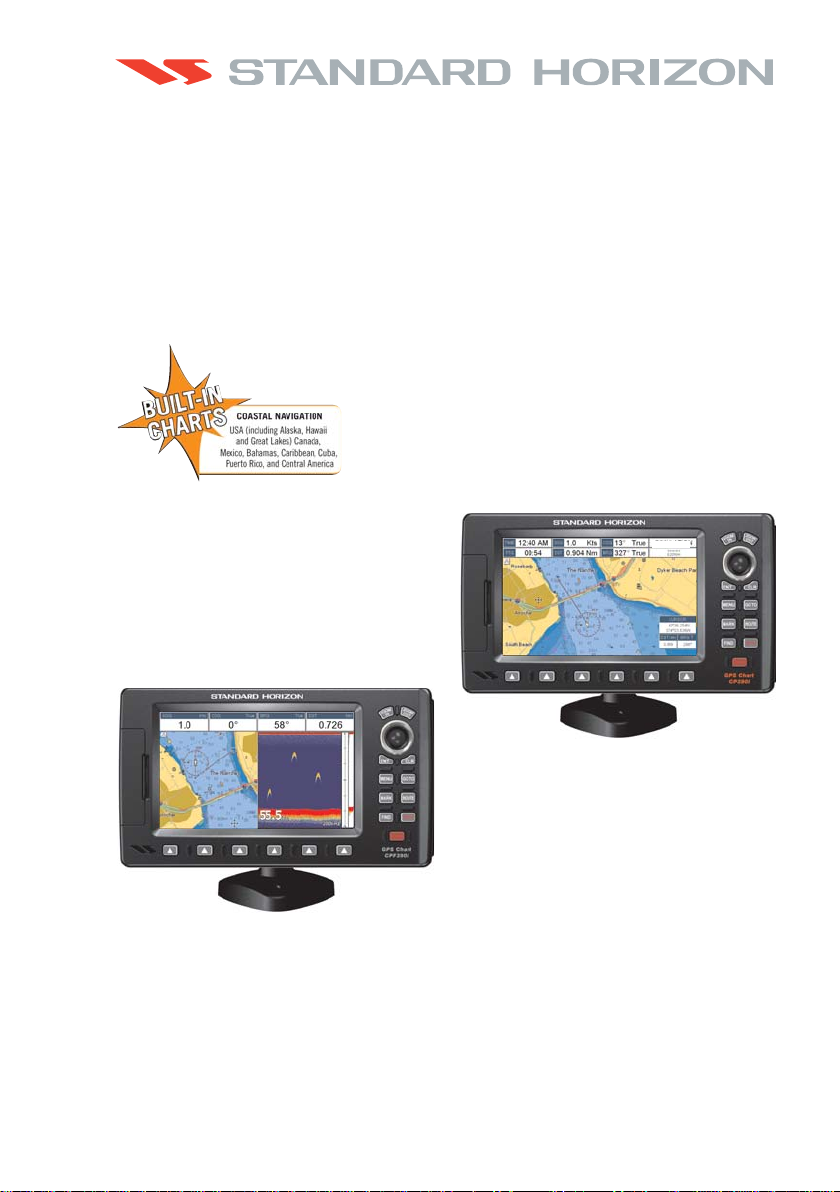
CP390i - GPS Chart Plotters
CPF390i - GPS Chart Plotters/Fish Finder
Owner's Manual
WAAS 3D
CP390i
CPF390i

WARNING!!!
Electronic charts displayed by the GPS Chart Plotter are believed to be accurate and
reliable, but are not intended to be a substitute for the official charts, which should
remain your main reference for all matters related to the execution of safe
navigation.
For this reason you should always keep the official published and approved nautical
charts on board.
FCC Compliance Statement
This device complies with Part 15 of the FCC limits for Class A digital devices. This
equipment generates, uses and can radiate radio frequency energy and, if not
installed or used in accordance with the instructions may cause harmful interference
with radio communications.
There is no guarantee that interference will not occur in a particular instance. If this
equipment does cause harmful interference to other equipment, try to correct the
problem by relocating the equipment.
Consult an authorized STANDARD HORIZON dealer or other qualified service
technician if the problem cannot be corrected. Operation is subject to the following
conditions: (1) This device cannot cause harmful interference, and (2) this device
must accept any interference received, including interference that may cause
undesired operation.
Copyright 2011. VERTEX STANDARD CO., LTD. All rights reserved. Printed in Italy.
No portion of this manual may be reproduced without the permission of VERTEX STANDARD CO., LTD.
OM CODE: S4x2SH8wc_0ww 16.50aD80 - 210111

CAUTION
- The GPS Chart Plotter is designed for maritime use. To avoid water intrusion,
ensure the C-MAP B
Y JEPPESEN C-CARD door is completely closed.
- Extensive exposure to heat may result in damage to the GPS Chart Plotter.
- The GPS Chart Plotter contains dangerous high-voltage circuits which only
experienced technicians can handle.
- STANDARD HORIZON will not be liable for errors contained herein, or for
incidental or consequential damages in connection with the performance or use
of this material.
CLEANING PROCEDURE FOR THE GPS CHART PLOTTER SCREEN
Cleaning of the chart plotter screen is a very important operation and must be done
carefully. Since the surface is covered by a antireflective coating, the procedure for
cleaning all the surfaces can be performed using the following procedure: Use a
clean, soft, lint-free cloth to clean the glass. We recommend using a micro-fiber
cloth. Spray a small amount of ammonia-free cleaner (isopropyl alcohol) onto the
cloth. Spraying on the cloth will prevent overspray. Fold the cloth or lens cloth into
a triangular shape, moisten the tip and use the index finger behind a corner to move
the cloth across the surface in overlapping side to side strokes. If the cloth is too wet,
a noticeable wet film will be left in its path and you will need to repeat the process.
If too dry, the cloth won’t glide easily, and may damage the surface.

Page 6 CP390i and CPF390i

TABLE OF CONTENTS
1. INTRODUCTION .................................................................................................................13
1.0 GENERAL INFORMATION ....................................................................................13
1.1 PACKING LIST ......................................................................................................14
1.1.0 Packing List ................................................................................................ 14
1.2 OPTIONAL DOME OR OPEN ARRAY RADAR ANTENNAS................................14
1.3 OPTIONAL ACCESSORIES .................................................................................. 15
2. INSTALLATION .................................................................................................................. 17
2.0 MOUNTING THE GPS CHART PLOTTER ............................................................ 17
2.1 BRACKET MOUNTING .......................................................................................... 17
2.2 FLUSH MOUNTING................................................................................................18
2.3 MOUNTING THE OPTIONAL EXTERNAL GPS ANTENNA ................................. 19
2.3.0 Flush mounting the antenna ...................................................................... 19
2.4 CONNECTIONS .....................................................................................................20
2.4.0 CP390i Connection Table.......................................................................... 21
2.4.1 CP390i Connections .................................................................................. 21
2.4.2 CPF390i Connection Table........................................................................23
2.4.3 CPF390i Connections ................................................................................ 23
2.5 BATTERY CONNECTIONS ................................................................................... 24
2.6 NMEA CONNECTIONS.......................................................................................... 24
2.7 GPS POSITION ON A VHF RADIO .......................................................................25
2.8 CP390i: OPTIONAL BLACK BOX FISH FINDER ..................................................25
2.9 RADAR ANTENNA (USA ONLY) ........................................................................... 25
2.10 PERSONAL COMPUTER CONNECTIONS...........................................................26
2.11 NMEA DATA PAGE................................................................................................26
2.12 CPF300i VIDEO INPUT..........................................................................................27
2.12.0 Video Camera Input ................................................................................... 27
2.12.1 VCR or DVD Input......................................................................................27
2.13 DEMO MODE (For DEALER USE) ........................................................................ 29
3. CONTROLS AND INDICATORS ...................................................................................... 31
3.0 CONTROLS AND CONNECTIONS .......................................................................31
3.0.0 The Soft Keys ............................................................................................32
3.1 GETTING STARTED .............................................................................................. 32
3.1.0 Power On, Off and ShuttlePoint Knob operation ...................................... 33
3.1.1 Cursor Vs. Home Mode ............................................................................. 34
3.1.2 Cursor and Menu selection speed.............................................................34
3.1.3 Changing the Ship Icons ........................................................................... 35
3.1.4 Changing the backlight and contrast ......................................................... 35
3.1.5 Selecting North Up or Course Up .............................................................. 36
3.2 AUTOMATIC TIME .................................................................................................36
3.3 SELECTING LORAN TD OR OTHER COORDINATE SYSTEM ..........................38
3.4 CHANGING THE CHART COLOR......................................................................... 38
3.5 SELECTING LANGUAGE ...................................................................................... 39
3.6 SELECTING PAGES USING SOFT KEYS............................................................40
3.7 CUSTOMIZING THE SOFT KEYS......................................................................... 40
3.8 SETTINGS IN GENERAL SETUP MENU.............................................................. 41
3.9 ABOUT PAGE ........................................................................................................ 43
CP390i and CPF390i Page 7

4. FIND SERVICES ..............................................................................................................45
4.0 USING FIND SERVICES & MORE FUNCTIONS .................................................. 45
4.0.0 Port Services..............................................................................................45
4.0.1 Port.............................................................................................................46
4.0.2 Tide Stations .............................................................................................. 46
4.0.3 Wrecks ....................................................................................................... 47
4.0.4 Obstructions...............................................................................................48
4.0.5 Lakes Information ...................................................................................... 49
4.0.6 Lakes By Name ......................................................................................... 51
4.0.7 Points Of Interest ....................................................................................... 51
4.0.8 User Points ................................................................................................ 52
4.0.9 Coordinates................................................................................................52
4.0.10 Information ................................................................................................. 53
5. MAX CARTOGRAPHY OVERVIEW................................................................................. 55
5.0 BUILT-IN CHARTS .................................................................................................55
5.0.0 Coverage areas and details.......................................................................55
5.0.1 Updating Built-In Charts.............................................................................55
5.1 INSERTING THE OPTIONAL MAX C-CARD ........................................................ 56
6. MAP FUNCTIONS ............................................................................................................ 59
6.0 MAX FUNCTIONS MENU ...................................................................................... 59
6.0.0 Zoom Type ................................................................................................. 59
6.0.1 Icon Size .................................................................................................... 60
6.0.2 Place Name Size ....................................................................................... 60
6.0.3 Perspective View .......................................................................................61
6.0.4 Dynamic Nav-Aids ..................................................................................... 62
6.0.5 Safety Status Bar (DSI - Data Safety Indicator)........................................62
6.0.6 Satellite Imagery ........................................................................................ 63
6.0.7 Currents Prediction .................................................................................... 64
6.0.8 Chart Language ......................................................................................... 65
6.0.9 Pictures or Diagrams ................................................................................. 65
How to show the Pictures or Diagrams of a Object .................................. 66
6.0.10 Enhanced Port Info .................................................................................... 67
7. CREATING MARKS .........................................................................................................69
7.0 CREATING A NEW MARK USING THE CHART PAGE ....................................... 69
7.1 EDITING A MARK .................................................................................................. 69
7.1.0 Deleting a Mark or Waypoint ..................................................................... 70
7.1.1 Moving a Mark or Waypoint ....................................................................... 70
7.2 MARKS/WAYPOINTS LIST ...................................................................................71
7.3 CREATING A NEW MARK WITH THE USER POINTS LIST ............................... 72
7.4 GOTO CURSOR, ROUTE AND MARK..................................................................73
8. MAN OVER BOARD (MOB) FUNCTION ......................................................................... 75
8.0 PLACING A MOB POINT ....................................................................................... 75
8.1 DELETING A MOB POINT ..................................................................................... 75
9. ROUTES ........................................................................................................................... 77
9.0 CREATING A ROUTE USING WAYPOINTS ........................................................77
9.1 CHANGING THE NAME OF A ROUTE .................................................................78
9.2 CREATING AN OLYMPIC ROUTE ........................................................................ 78
9.3 MAKING ADDITIONAL ROUTES...........................................................................79
Page 8 CP390i and CPF390i

9.4 CREATING A ROUTE USING MARKS ON THE CHART PAGE .......................... 79
9.5 INSERTING A WAYPOINT INTO A ROUTE ......................................................... 80
9.6 GOTO A ROUTE ....................................................................................................80
9.6.0 Using [GOTO] to select Route...................................................................80
9.6.1 Using the ShuttlePoint knob ...................................................................... 81
9.7 DELETING A ROUTE.............................................................................................81
9.8 OTHER SETTINGS IN ROUTE MENU .................................................................. 82
9.8.0 Route Check .............................................................................................. 82
10. TRACKS ........................................................................................................................... 85
10.0 TRACKING .............................................................................................................85
10.0.0 Saving and starting a new Track ............................................................... 86
10.0.1 Deleting a Track......................................................................................... 86
10.0.2 Other settings ............................................................................................. 86
10.1 TRIP LOG ............................................................................................................... 87
10.1.0 Using the Trip Log ..................................................................................... 87
10.1.1 Setup / Reset ............................................................................................. 87
11. USER C-CARD ................................................................................................................. 89
11.0 USER C-CARD MENU ...........................................................................................89
11.0.0 Formatting the optional User C-CARD ...................................................... 89
11.0.1 Transferring files to the optional User C-CARD ........................................ 89
11.0.2 Loading a file from the optional User C-CARD .........................................90
11.0.3 Deleting a file from the optional User C-CARD ......................................... 90
11.0.4 Refreshing the optional User C-CARD ...................................................... 90
12. PAGES ............................................................................................................................91
12.0 CHART PAGE ........................................................................................................ 92
12.0.0 Focus Soft Key on Dual Chart Page .........................................................93
12.0.1 Single Chart Page...................................................................................... 94
12.0.2 Window Selections ....................................................................................94
12.0.3 Customizing the Data Windows ................................................................95
12.0.4 Additional Functions on Chart Page.......................................................... 96
12.0.5 Turning Off Information on Icon Points .....................................................96
12.0.6 Display Mode .............................................................................................97
12.0.7 Marine Settings .......................................................................................... 98
12.0.8 Depth Settings ...........................................................................................98
12.0.9 Land Settings ............................................................................................. 99
12.0.10Chart Settings ............................................................................................ 99
12.0.11Underwater Objects Settings ................................................................... 100
12.1 CUSTOMIZING CHART SETTINGS .................................................................... 101
12.2 NAVIGATION PAGE ............................................................................................ 101
12.3 HIGHWAY PAGE ................................................................................................. 102
12.4 CELESTIAL PAGE ............................................................................................... 102
12.5 GPS STATUS PAGE ............................................................................................ 103
12.5.0 WAAS/EGNOS Setting ............................................................................ 104
12.5.1 Setup Menu..............................................................................................104
12.6 NMEA DISPLAY PAGE ........................................................................................ 105
12.7 NMEA DATA PAGE..............................................................................................105
12.8 NMEA TREND PAGES ........................................................................................ 106
12.9 VHF DIGITAL SELECTIVE CALLING .................................................................. 107
12.9.0 Interfacing ................................................................................................ 108
12.9.1 Distress Call............................................................................................. 108
CP390i and CPF390i Page 9

12.9.2 Position Request......................................................................................108
13. ADVANCED SETTINGS ................................................................................................. 111
13.0 INPUT/OUTPUT (NMEA, AIS, RADAR) .............................................................. 111
13.0.0 Input ........................................................................................................ 111
13.0.1 Ouput .......................................................................................................111
13.1 NAVIGATE ...........................................................................................................112
13.1.0 Loran TD .................................................................................................. 113
13.2 COMPASS ............................................................................................................113
13.3 ALARMS ...............................................................................................................114
13.4 SIMULATION ....................................................................................................... 114
13.4.0 Navigating a Route in Simulation mode ..................................................115
13.5 DSC POLLING......................................................................................................115
14. AIS .................................................................................................................................. 117
14.0 SYSTEM DEFINITIONS .......................................................................................117
14.1 MENU ................................................................................................................... 118
14.2 AIS SETUP ........................................................................................................... 118
14.3 QUICK INFO ON AIS TARGET............................................................................118
14.4 LIST ...................................................................................................................... 119
14.5 AIS TARGET COLORS ........................................................................................ 119
15. C-WEATHER SERVICE..................................................................................................121
15.0 C-WEATHER SERVICE MENU ........................................................................... 121
15.0.0 Download ................................................................................................. 121
15.0.1 Copy From User C-CARD .......................................................................122
15.0.2 Weather Forecast .................................................................................... 122
15.0.3 Real Time View........................................................................................ 122
15.0.4 Type of Data ............................................................................................ 122
16. MOBILARM ..................................................................................................................... 123
16.0 MOBILARM-GPS CHART PLOTTER CONNECTION ......................................... 123
16.1 SOFTWARE SETUP ............................................................................................ 124
16.2 MOBILARM STATUS ...........................................................................................124
16.3 MOBILARM PTX ................................................................................................... 125
16.3.0 MOBILARM MOB alert is received .......................................................... 125
16.4 PLACING CURSOR ON THE PTX ICON ............................................................126
16.4.0 Delete PTX............................................................................................... 126
16.4.1 Goto PTX .................................................................................................126
16.4.2 The MOBILARM Alarm Status List..........................................................127
17. FISH FINDER ................................................................................................................. 129
17.0 ENABLE/DISABLE ............................................................................................... 129
17.1 UNDERSTANDING THE FISH FINDER PAGE ................................................... 130
17.1.1 Understanding the Fish Finder display.................................................... 131
17.2 DISPLAYING THE FISH FINDER PAGE.............................................................132
17.2.0 Auto Full Page .........................................................................................133
17.2.1 200 kHz Full, 50 kHz Full and 50&200kHz Display Pages ..................... 133
17.2.2 200 kHz and 50 kHz Zoom Pages...........................................................133
17.2.3 200 kHz and 50 kHz Fish/Chart Pages ................................................... 134
17.2.3.0 Focus Soft Key on FISH/CHART Page .................................... 134
17.2.4 Radar Pages ............................................................................................ 134
17.2.4.0 Fish/Radar/Chart Page ............................................................. 134
Page 10 CP390i and CPF390i

17.2.4.1 Radar Combo Page................................................................... 135
17.2.4.2 Focus Soft Key .......................................................................... 135
17.3 SOFT KEY OPERATION.........................................................................136
17.4 SETUP MENU ......................................................................................... 136
17.5 PRESETS ................................................................................................ 137
17.6 FREQUENCY...........................................................................................137
17.7 GAIN MODE ............................................................................................ 138
17.7.0 Auto Mode ..................................................................................138
17.7.1 Manual Mode ..............................................................................138
17.8 RANGE MENU.........................................................................................138
17.8.0 Range Mode ............................................................................... 138
17.8.0.0 Manual Mode................................................................138
17.8.0.1 Auto Range ..................................................................138
17.8.0.2 Bottom Lock ................................................................. 138
17.8.1 Depth .......................................................................................... 139
17.8.2 Shift ............................................................................................ 139
17.9 INTERFERENCE REJECTION ............................................................... 139
17.10 SENSITIVITY MENU ............................................................................... 139
17.10.0 Gain ............................................................................................ 140
17.10.1 STC (Sensitivity Time Control)...................................................140
17.10.2 Surface Noise Filter....................................................................141
17.11 DISPLAY SETUP.....................................................................................142
17.11.0 Color Settings ............................................................................. 142
17.11.1 Scrolling Speed .......................................................................... 142
17.11.2 White Line .................................................................................. 142
17.11.3 Fish Symbols .............................................................................. 143
17.12 TRANSDUCER SETUP ........................................................................................ 143
17.13 ALARMS ............................................................................................................... 144
17.14 SAVE SETTINGS TO USER C-CARD ................................................................. 145
17.15 LOAD SETTINGS FROM USER C-CARD ........................................................... 145
17.16 RESTORE CURRENT PRESET DEFAULTS ...................................................... 145
17.11.4 A-Scope ...................................................................................... 143
17.12.0Keel Offset ............................................................................................... 143
17.12.1Calibrate Water Speed ............................................................................143
17.12.2Calibrate Water Temp ............................................................................. 143
17.12.3Set Defaults ............................................................................................. 144
17.13.0Shallow Water .......................................................................................... 144
17.13.1Deep Water .............................................................................................. 144
17.13.2Fish .......................................................................................................... 144
17.13.3Temperature Upper..................................................................................144
17.13.4Temperature Lower .................................................................................. 144
17.13.5Temperature Rate.................................................................................... 145
18. TROUBLESHOOTING....................................................................................................147
19. TECHNICAL TESTS ...................................................................................................... 149
19.0 SYSTEM TEST .................................................................................................... 149
19.0.0 RAM Menu (reset)....................................................................................149
19.0.1 DIM Menu.................................................................................................149
19.0.2 Cartridges.................................................................................................150
19.0.3 Serial Ports ..............................................................................................150
CP390i and CPF390i Page 11

20. SPECIFICATIONS ....................................................................................................151
20.0 CP390i/CPF390i SPECIFICATIONS .................................................................... 151
20.1 CPF390i FISH FINDER SPECIFICATIONS.........................................................151
20.2 CP390i/CPF390i DIMENSIONS ........................................................................... 152
20.3 OPTIONAL FF525 FISH FINDER SPECIFICATIONS (use with CP390i)........... 152
20.4 OPTIONAL WAAS GPS RECEIVER SPECIFICATIONS....................................153
21. APPENDIX: TERMS .......................................................................................................155
ANALYTICAL INDEX ............................................................................................................ 159
Page 12 CP390i and CPF390i

1. INTRODUCTION
Congratulations on your purchase of the Standard Horizon GPS Chart Plotter. Whether this
is your first Navigation device, or if you have other STANDARD HORIZON equipment,
STANDARD HORIZON organization is committed to ensuring your enjoyment of this
Navigation device. STANDARD HORIZON technical support personnel stand behind every
product we sell. Our Product Support team invites you to contact us should you require
technical advice or assistance, at 800/767-2450 or marinetech@vxstdusa.com.
1.0 GENERAL INFORMATION
The CP390i (with internal GPS antenna) and CPF390i (with internal GPS antenna and Fish
Finder) are precision-crafted high-performance receivers for the Global Positioning System
(WAAS GPS) constellation of satellites that provide precise location data with a host of
navigation features and are ideal for nautical use and sealed against water ingress. The
CP390i and CPF390i are housed in rugged, impact-resistant cases with outstanding
ergonomic design for effortless operation. The CP390i and CPF390i are IP56 water resistent.
The advanced features of the GPS Chart Plotter/Fish Finder include:
· Built-In Charts for coastal navigation of USA including Alaska, Hawaii and Great Lakes,
Canada, Bahamas, Caribbean, Cuba, Puerto Rico, and Central America
· 7” 800x480 high resolution sunlight-readable display
· Internal 50 channel WAAS GPS antenna
· Optional connection for external 50 channels WAAS GPS antenna with 30 feet of cable
· Video Input with ”picture-in-picture” display
· Dual chart window with independent zoom levels
· CP390i: Fish Finder capable when the optional FF525 50/200kHz (Black Box Fish
Finder) are installed. Radar / AIS capable
· CPF390i: Built-in Fish Finder. Radar and AIS capable
· Selectable sailboat and power boat ship icons with red and green for port and starboard
· Compass Rose indication around ship icon
· Satellite images on base chart
· Route Checking
· Color Targets AIS
· Dedicated AIS List page
· Navigate to an Olympic Route
· SOG Speed Filter function to resolve erratic speed redings in rough seas
· Dedicated MARK, ROUTE and FIND keys
· Supplied swivel mounting bracket and flush mounting hardware
· CP390i: NMEA 0183 connections: 4 Inputs, 5 Outputs
· CPF390i: NMEA 0183 connections: 3 Inputs, 3 Outputs
· 3000 Marks / 50 Routes / 10000 Track Points
· 3 year Waterproof Warranty
CPF390i: Fish Finder features:
· 256 colors display
· Built-in 600W Dual Frequency Fish Finder
CP390i and CPF390i Page 13

· 50 and 200kHz Frequency selection
· 2x and 4x Zoom
· Bottom Lock and White Line selections
· Sensitivity Time Control (STC) and Surface Noise Filter
· Speed through water (if available on transducer)
· Alarms - Shallow, Depth, Temp Upper and Lower
· Temperature (if available on transducer)
1.1 PACKING LIST
When the package containing the Navigation device is first opened, please check for the
following contents. If any parts are missing contact the dealer this Navigation device was
purchased from.
Accessories and replacement parts may be ordered from STANDARD HORIZON’s Parts
Department at 741/827-7600 extension 6800 or e-mail at yaesuparts@vxstdusa.com.
1.1.0 Packing List
PART CODE ITEM
S8002224A External bracket
S8002225 Mounting knob with two washers
S8002235 Dust cover
T9101553 Power & Accessory cable
S8002223 Flush mounting screws
EM022U500 Flush mount template
XUCMP0052 2 Amp fuse and holder
EM051U100 Owner’s Manual
EM023U511 Quick Reference Guide
1.2 OPTIONAL DOME OR OPEN ARRAY RADAR ANTENNAS
The Radar antennas are supplied by SI-TEX (631) 996-2690 in the USA and Canada. Refer
to the table below for compatible models:
MODEL NUMBER DESCRIPTION
MDS-1 2kW 24 Mile 12.4” diameter Radome antenna
MDS-8 2kW 24 Mile 20” diameter Radome antenna
MDS-9 4kW 36 Mile 23.5” diameter Radome antenna
MDS-10-4 4kW 48 Mile 4FT Open Array
MDS-10-5 4kW 48 Mile 5FT Open Array
NOTE
For additional information, refer to the Radar Installation and Radar Operation Manuals located at
www.standardhorizon.com.
Page 14 CP390i and CPF390i
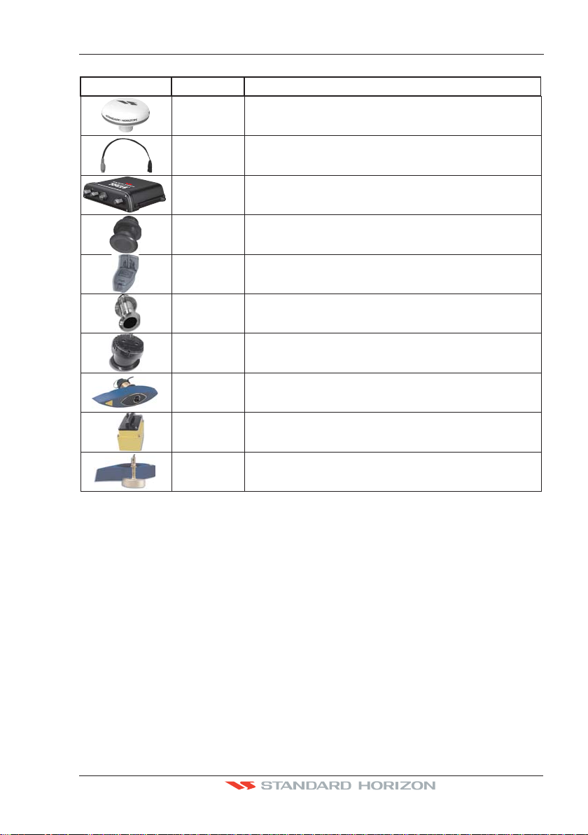
1.3 OPTIONAL ACCESSORIES
ACCESSORIES PARTS NAME ITEM
Dual Frequency Fish Finde
Q7000619A
ACVC10 Video Adapter cable
r
FF525 50/200kHz Black Box Fish Finder
50 Channel GPS Antenna Unit GSU-5H Series UXOGSU51SD
(AAF69X001)
(CP390i ONLY)
DST520 600W 2" Nylon Thru-hull depthtempTransducer
DST521 600W Transom mount depth, speed temp Transducer
DST523 600W 2" Bronze Thru-hull depthtemp Transducer
DST525 600W In-hull Transducer
DST526
DST527 1000W In-hull depth Transducer
DST528A 1000W Bronze long stem depthtemp Transd.
600W 2" Bronze Thru-hull depth,speed temp Transducer
(FF525 ONLY)
()FF525 ONLY
CP390i and CPF390i Page 15

Page 16 CP390i and CPF390i

2. INSTALLATION
NOTE
Throughout this Owner’s Manual same conventions are used. See the legend below:
[MENU]If you see brackets around a bold and capital letter word this refers to a key press.
[CHART] If you see brackets around a bold and small capital letter word this refers to a Soft Key
press.
GENERAL SETUP When a word(s) is bold capital letters and underlined, this refers to a menu
A GPS receiver and antenna are located inside the CP390i and CPF390i and are designed
to be bracket mounted. Both models may be flush mounted, however an optional external
GPS antenna may be needed to receive GPS satellite signals.
To use the external GPS antenna, the internal GPS antenna must be turned off, using the
procedure below:
1. Turn the CP390i and CPF390i On an d s e le c t t h e
2. Press [ENT] to show the
3. Move the ShuttlePoint knob to highlight
4. Move the ShuttlePoint knob to highlight
selection item.
GPS SETUP menu.
INTERNAL GPS
RESTART GPS
NAVIGATION SPEED
NAVIGATION FILTER High
DIFF CORRECTION SOURCE WAAS/EGNOS
INTERNAL GPS and press [ENT].
OFF and press [ENT].
Off
On
Figure 2 - GPS Setup menu
GPS STATUS page.
5. Press [CLR] to exit the GPS SETUP menu.
6. Confirm the GPS Status page is showing satellite signal strength bars and receive a fix.
2.0 MOUNTING THE GPS CHART PLOTTER
The CP390i and CPF390i are supplied with a swivel mounting bracket which allows them
to be dash mounted. When flush mounting, the optional GPS antenna may be needed to
receive GPS satellite signals. Refer to the images below for Bracket and Flush mounting.
NOTE
The CP390i and CPF390i are designed to be bracket and flush mounted. However when bracket
mounting the CP390i and CPF390i in an area where satellite reception is not possible with the
internal antenna or when flush mounted, the optional GPS antenna must be installed.
2.1 BRACKET MOUNTING
Before installing ensure the area the bracket is mounted to is strong enough to support the
weight of the GPS Chart Plotter especially while under way. After the location is found,
CP390i and CPF390i Page 17
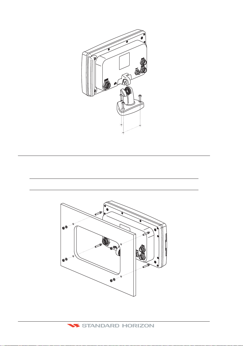
attach the mounting base to the area using the supplied hardware.
Figure 2.1 - Example of Bracket installation
2.2 FLUSH MOUNTING
The CP390i and CPF390i are supplied with a flush mount template for the cutout hole and
screw holes required to install the GPS Chart Plotter.
NOTE
Before drilling holes make sure there is enough room to mount the GPS Chart Plotter and there
are no obstructions.
Figure 2.2 - Example of Flush installation
Page 18 CP390i and CPF390i

1. After a location is found, peel the template label from the backing and apply the label
to the mounting area.
2. Drill a hole in one area of the cutout area that will allow the blade of a jig saw to be
inserted. Insert and cut out the area on the panel using the jig saw.
3. Next drill the four holes required to insert the GPS Chart Plotter with the mounting studs.
4. Install the mounting studs on the GPS Chart Plotter and insert into the mounting hole.
5. Attach the GPS Chart Plotter to the mounting location by attaching the supplied
hardware to the mounting studs.
2.3 MOUNTING THE OPTIONAL EXTERNAL GPS ANTENNA
An external WAAS GPS antenna is available when the CP390i and CPF390i is flush
mounted or mounted in an area where satellite reception is not possible with the internal
antenna.This antenna is designed to be mounted on a base, installed on an extension or
flush mounted.
Choose a location for the antenna that has a clear view of the sky and is not located within
3Feet of a Radar or other transmitting antennas. Ensure there are no major obstructions or
fixtures in the immediate proximity to the antenna. The antenna relies on direct “line of sight”
satellite reception. If you are unsure of the chosen location, temporarily mount the antenna
in the desired location to verify correct operation. If mounted close to Radar, after the GPS
Chart Plotter has a fix, turn on the Radar to ensure the GPS Chart Plotter holds the fix (use
the GPS Status Page).
The thread used on the antenna is an industry standard (1inch 14TPI) used on a wide range
of mounting brackets.
NOTE
The antenna cable can be cut and spliced to ease installation. Care must be taken when
reconnecting the antenna cable to protect from water and corrosion.
2.3.0 Flush mounting the antenna
NOTE
Before drilling holes, it is recommended the antenna be positioned where the location is planned,
cable connected to the GPS Chart Plotter and power turned on to ensure a GPS Fix is received.
1. Remove the threaded base from the antenna dome.
2. To ease installation a flush mounting template for the antenna has been included.
3. Apply the mounting template sticker to the area that was verified for GPS reception.
4. Then, drill out the 0.78” (20mm) and 0.13” (3.2mm) holes, and remove the template.
5. Insert the cable into the 0.78” (20mm) hole and route to the GPS Chart Plotter.
6. Apply a small amount or RTV to the underside of the antenna.
7. Place the antenna and then screw it into place using the screws.
NOTE
In some cases the screw may not be long enough. If this happens simply apply more RTV to the
underside of the antenna to glue it into place.
CP390i and CPF390i Page 19

Figure 2.3.0 - Installing the External GPS antenna (I)
Figure 2.3.0a - Installing the External GPS antenna (II)
Smart GPS Cable
Pin Wire Color Description
1 Red Battery Positive
2 Green Smart GPS NMEA Input
3 Brown Smart GPS NMEA Output
4NC
5NC
6 Black/Yellow Battery Ground
S8002348
3.2m
0.13”[Ø
0.78" [Ø20 mm]
GPS OVERALL SHAPE
]
m
2.4 CONNECTIONS
The CP390i and CPF390i have connectors that allow them to be connected to a power
supply, optional WAAS GPS antenna, optional FF525 50/200kHz BLACK BOX FISH
FINDER (only for CP390i) and NMEA Devices* such as Optional Video Camera, VHFs, AIS
Receiver, Digital Instruments and autopilots.
NOTE*
RS232 not opto-isolated electrical interface
Page 20 CP390i and CPF390i

NOTE
The GPS Chart Plotter can send many sentences to external NMEA devices*. The NMEA Output
wires are yellow and white. If you have connected devices as shown in the table on the next page
and need to feed NMEA to other devices (Autopilot, RADAR…) you can parallel wires from the
yellow, brown or white wires to other devices.
2.4.0 CP390i Connection Table
12VDC Power Cable
Pin Wire Color Description Connection Example Additional Comments
1 Black Battery Ground Connect to Battery Ground
2 Red Battery Positive Connect to Battery Positive
3 Green NMEA Common Common (ground) for NMEA devices*
4 Blue Port 1 Input Connect to Output of NMEA devices* Default is NMEA0183
5 Brown Port 1 Output Connect to Input of NMEA devices* Default is NMEA0183 with GGA, GLL, RMC,
6 Grey Port2 Input Connect to FF525 Default is Fish Finder
7 White Port2 Output Connect to FF525 Default is Fish Finder
8 Yellow Port 3 Output Connect to Input of NMEA devices* Default is NMEA0183 with APA, APB, BOD,
NMEA ACC 2 Cable
Pin Wire Color Description Connection Example Additional Comments
1 Black NC
2 Red NC
3 Green NMEA Common Common (ground) for NMEA devices*
4 Blue Port 4 Input Connect to Output of NMEA devices* Default is NMEA0183*
5 Brown Port 4 Output Connect to Input of NMEA devices* Default is NMEA0183 with GLL, RMB, RMC
6 Grey Port 5 Input Connect to Output of NMEA devices* Default is NMEA0183
7 White Port 5 Output Connect to Input of NMEA devices* Default is NMEA0183 with GLL, RMB, RMC
8 Yellow NC
*NOTE
RS232 not opto-isolated electrical interface.
XTE, DBT, DPT, MTW, VHW sentences
GGA, GLL, RMC and BOD sentences
and XTE sentences
and XTE sentences
2.4.1 CP390i Connections
2.4.1.0 DC Power Connection
Optional
WAAS GPS
Antenna
ACC 2 Cable - Not used
CP390i
Red
2A
Fuse
Switch
-
+
Battery
10-35Vdc
Black
PWR & ACC 1 Cable
CP390i and CPF390i Page 21
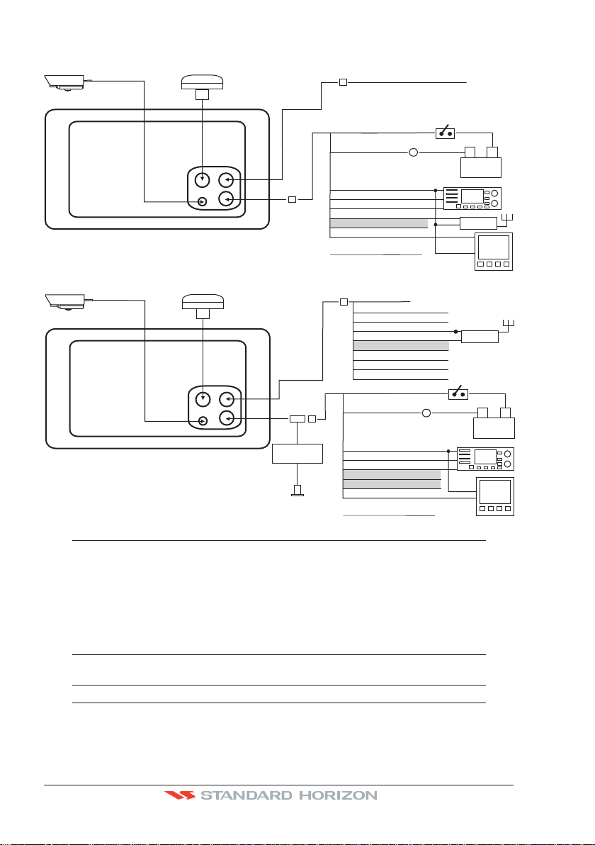
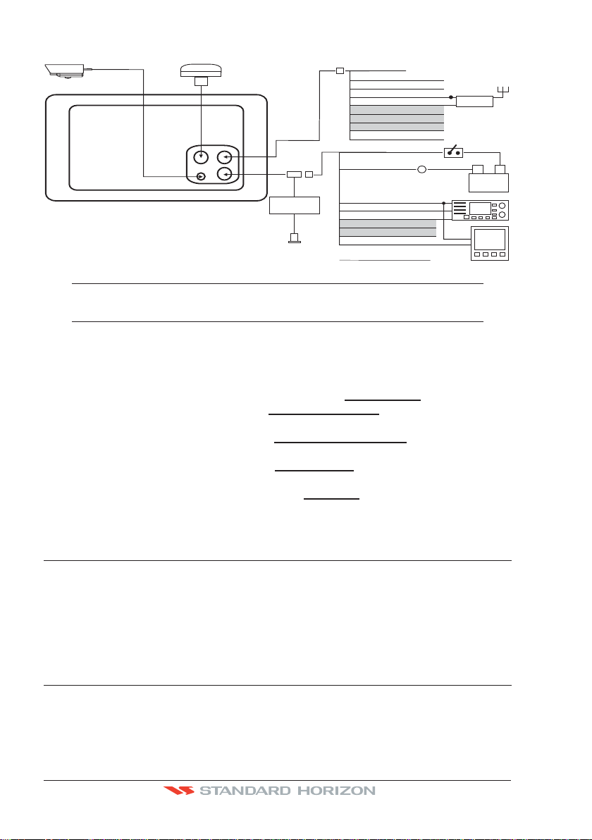
2.4.1.1 Connection a VideoCamera, FF525, AIS receiver, VHF and Autopilot
VIDEO
Camera
CP390i
VIDEO
Camera
CP390i
Optional
WAAS GPS
Antenna
Optional
WAAS GPS
Antenna
Transducer
Tee
Optional
Fish Finder
ACC 2 Cable - Not used
Red
Black
NMEA Common
Green
Port 1 Input
Blue
Port 1 Output
Brown
Port 2 Input
Gray
Port 2 Output
White
Port 3 Output
Yellow
PW
R &
ACC 1 Cable
ACC 2 Cable
No Connection
Red
No Connection
Black
NMEA Common
Green
Port 4 Input
Blue
Port 4 Output
Brown
Port 5 Input
Gray
Port 5 Output
White
No Connection
Yellow
Red
Black
NMEA Common
Green
Port 1 Input
Blue
Port 1 Output
Brown
Port 2 Input
Gray
Port 2 Output
White
Port 3 Output
Yellow
PW
R
&
A
CC 1 Cable
2A
Fuse
2A
Fuse
Switch
Switch
-
Battery
10-35Vdc
VHF
AIS
AIS
10-35Vdc
NOTE
Port2 Input and Output is used by the optional FF525. In the diagram above you will notice Port2
Input and Output wires are shown in gray and not used.
Port4, and 5 Outputs are can be connected to NMEA devices*capable of listening to NMEA0183
sentences.
Port4, and 5 Inputs can be connected to NMEA devices* capable of outputting to NMEA0183
sentences.
The Input and Output baud rate for each Port is set using the Advanced
Setup>In/Out Connections menu. For example if Port1 is set for AIS 38400, the
Input Port operates at 38400 baud and the Output Port is disabled.
+
PILOT
-
Battery
VHF
PILOT
+
NOTE*
RS232 not opto-isolated electrical interface.
2.4.1.2 AIS Setup
The CP390i has to be set up to be able to receive NMEA information from the AIS receiver.
Page 22 CP390i and CPF390i

The GPS Chart Plotter reads the AIS NMEA message VMD, type 1, 2, 3 and 5 for AIS Class
A and type 18, 19, 24 for AIS Class B. Select the used port and transmission speed by
following the procedure:
The CP390i has to be setup to be able to receive NMEA information from the AIS receiver.
1. Press [MENU], move the ShuttlePoint knob to highlight
2. Move the ShuttlePoint knob to highlight
ADVANCED SETUP and press [ENT] or move
SETUP MENU and press [ENT].
the ShuttlePoint knob to the right.
3. Move the ShuttlePoint knob to highlight
IN/OUT CONNECTIONS and press [ENT] or
move the ShuttlePoint knob to the right.
4. Move the ShuttlePoint knob to highlight
PORT4 INPUT (or other Port the AIS is
connected to) and press [ENT] or move the ShuttlePoint knob to the right.
5. Move the ShuttlePoint knob up/down to select
AIS 38400 and press [ENT] or move the
ShuttlePoint knob to the right.
2.4.2 CPF390i Connection Table
12VDC Power
Pin Wire Color Description Connection Example Additional Comments
1 Black Battery Ground &
Common for and signal ground
NMEA devices*
2 Red Battery Positive Connect to Battery Positive
3 Green Port3 Input Connect to Output of NMEA devices* Default is NMEA0183
4 Blue Port1 Input Connect to Output of NMEA devices* Default is NMEA0183
5 Brown Port1 Output Connect to Input of NMEA devices* Default is NMEA0183 with GGA, GLL, RMC,
6 Gray Port2 Input Connect to Output of NMEA devices* Default is NMEA0183
7 White Port2 Output Connect to Input of NMEA devices* Default is NMEA0183 with GGA, GLL, RMC
8 Yellow Port3 Output Connect to Input of NMEA devices* Default is NMEA0183 with APA, APB, BOD,
*NOTE
RS232 not opto-isolated electrical interface.
Connect to Battery Ground and
XTE, DBT, DPT, MTW, VHW sentences
and XTE sentences
GGA, GLL, RMC and BOD sentences
2.4.3 CPF390i Connections
2.4.3.0 DC Power Connection
Optional WAAS GPS
antenna
CPF390i
Red
2A
Fuse
Switch
-
Battery
10-35Vdc
Black
PWR & ACC 1 Cable
Transducer
CP390i and CPF390i Page 23
+
2.4.3.1 Connection a VideoCamera, AIS Receiver, VHF and Autopilot
VIDEO
Camera
CP300
SMART GPS
Antenna
Transducer
Tee
FF520
Optional
Fish Finder
ACC 2 Cable
No Connection
Red
No Connection
Black
NMEA Common
Green
Port 4 Input
Blue
Port 4 Output
Brown
Port 5 Input
Gray
Port 5 Output
White
No Connection
Yellow
Red
Black
NMEA Common
Green
Port 1 Input
Blue
Port 1 Output
Brown
Port 2 Input
Gray
Port 2 Output
White
Port 3 Output
Yellow
PWR & ACC 1 Cable
2A
Fuse
Switch
AIS
-
Battery
10-35Vdc
VHF
PILOT
+
NOTE
The Input and Output baud rate for each port is set using the Advanced
Setup>In/Out Connections menu. For example if Port1 is set for AIS 38400, the
Input and Output both operate at 38400 baud.
2.4.3.2 AIS Setup
The CPF390i has to be set up to be able to receive NMEA information from the AIS receiver.
The GPS Chart Plotter reads the AIS NMEA message VMD, type 1, 2, 3 and 5. Select the
used port and transmission speed by following the procedure:
1. Press [MENU], move the ShuttlePoint knob to highlight
2. Move the ShuttlePoint knob to highlight
ADVANCED SETUP and press [ENT] or move
SETUP MENU and press [ENT].
the ShuttlePoint knob to the right.
3. Move the ShuttlePoint knob to highlight
IN/OUT CONNECTIONS and press [ENT] or
move the ShuttlePoint knob to the right.
4. Move the ShuttlePoint knob to highlight
PORT2 INPUT and press [ENT] or move the
ShuttlePoint knob to the right.
5. Move the ShuttlePoint knob up/down to select
AIS 38400 and press [ENT] or move the
ShuttlePoint knob to the right.
2.5 BATTERY CONNECTIONS
1. The GPS Chart Plotters are supplied with a fuse and holder. This fuse should be
installed into the Black wire to protect the NMEA Output/Input circuits from possible
damaged.
2. Connect the Red and Black wires from the GPS Chart Plotter to a 12VDC source as
directly as possible.
2.6 NMEA CONNECTIONS
The GPS Chart Plotter can be connected to external devices with NMEA and display
information, examples:
· DSC VHF Radio
· Depth Sounder, Speed Log, Wind Instrument, Autopilot etc.
Page 24 CP390i and CPF390i
· Radar (USA ONLY)
D
u
a
l
F
re
q
u
e
n
c
y
F
is
h
F
in
d
e
r
Dual
Frequency
Fish
Finder
· Personal Computer
· AIS Receiver
· MOBILARM System
2.7 GPS POSITION ON A VHF RADIO
STANDARD HORIZON has pioneered Digital Selective Calling (DSC) on VHF radios.
Advancements in DSC have made it possible to show the coordinates of a vessel that has
transmitted a DSC Distress Call or even Polled the location of another vessel and show
the position of that vessel on the display of STANDARD HORIZON VHFs.
STANDARD HORIZON has taken this feature one step further. If a CP390i or CPF390i is
connected to a DSC capable VHF, the vessel in Distress or the polled position of the vessel
is shown on the display of the GPS Chart Plotter, making it easy to navigate to the location
of the vessel. This is a great feature that could save someone’s life or for anyone wanting
to know the position of another vessel.
Other DSC VHF Manufactures
GPS Chart Plotter Description VHF
Green NMEA Common Ground Connect to NMEA Ground
Brown NMEA Positive Output Connect to NMEA Input
Blue NMEA Positive Input * Connect to NMEA Output (if available)
* Some manufacturers of DSC VHF’s are not capable of outputting NMEA DSC and DSE sentences to
the CP390i or CPF390i. Refer to the Owner’s Manual and confirm the VHF can output NMEA DSC
and DSE sentences.
NOTE
Refer to VHF Digital Selective Calling Section for operation.
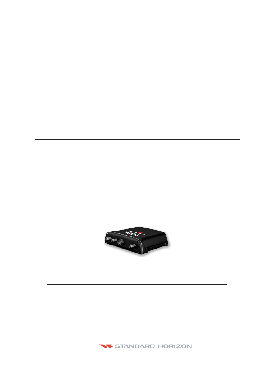
2.8 CP390i: OPTIONAL BLACK BOX FISH FINDER
STANDARD HORIZON offers an optional BLACK BOX FISH FINDER called the FF525. Please
refer to the Owner's Manual supplied with the Fish Finder for connections and operation.
Figure 2.8 - FF525 50/200kHz BLACK BOX FISH FINDER
NOTE
The FF520 is also compatible.
2.9 RADAR ANTENNA (USA ONLY)
Please refer to Par. “1.3 Radar Unit supplied by SI-TEX USA”. The Radar antenna includes the
necessary electronics to deliver Radar information to a compatible STANDARD HORIZON
GPS Chart Plotter, and is supplied with mounting hardware kit, interconnection cable and
a Radar Junction Box.
CP390i and CPF390i Page 25

Please refer to the Radar Installation Manual and Radar Operation Manual available at
www.standardhorizon.com.
2.10 PERSONAL COMPUTER CONNECTIONS
The GPS Chart Plotter can be connected to output Marks and Routes to many available PC
programs. To send or receive User Points the PC Program must be able to receive NMEA
WPL and RTE sentences. Refer to the table below for connection to a Serial DB9 connector.
Pin PC DB9 connection Port 1 connection
2 Receive Brown
3 Transmit Blue
5 Signal ground Green
By default Port1 is set to receive or send User Points to and from a PC. The GPS Chart
Plotter may be set up to send and receive the User Points on a different Port using the
following procedure:
1. Press [MENU], move the ShuttlePoint knob to highlight
2. Move the ShuttlePoint knob to highlight
ADVANCED SETUP and press [ENT] or move
the ShuttlePoint knob to the right.
3. Move the ShuttlePoint knob to highlight
IN/OUT CONNECTIONS and press [ENT] or
move the ShuttlePoint knob to the right.
4. Move the ShuttlePoint knob to highlight
SEND/REC RTE & MARKS and press [ENT]
or move the ShuttlePoint knob to the right to show the popup window.
5. Move the ShuttlePoint knob to desired Port and press [ENT].
The PC COM settings are:
· Baud Rate : 4800
· Parity : None
· Data Bits : 8
· Stop Bits : 1
· Flow Control : None
SETUP MENU and press [ENT].
The format of the sentences that are sent:
· MARK $GPWPL,3249.061,N,00710.651,E,MRK002*22
· WAYPOINT $GPWPL,3933.008,N,00639.969,E,WPT012*22
· ROUTE $GPWPL,2544.362,N,08011.672,W,WPT003*32
$GPWPL,2543.921,N,08011.481,W,WPT004*31
$GPWPL,2543.493,N,08011.768,W,WPT005*37
$GPRTE,2,1,c,ROUTE01,WPT003,WPT004,WPT005*21
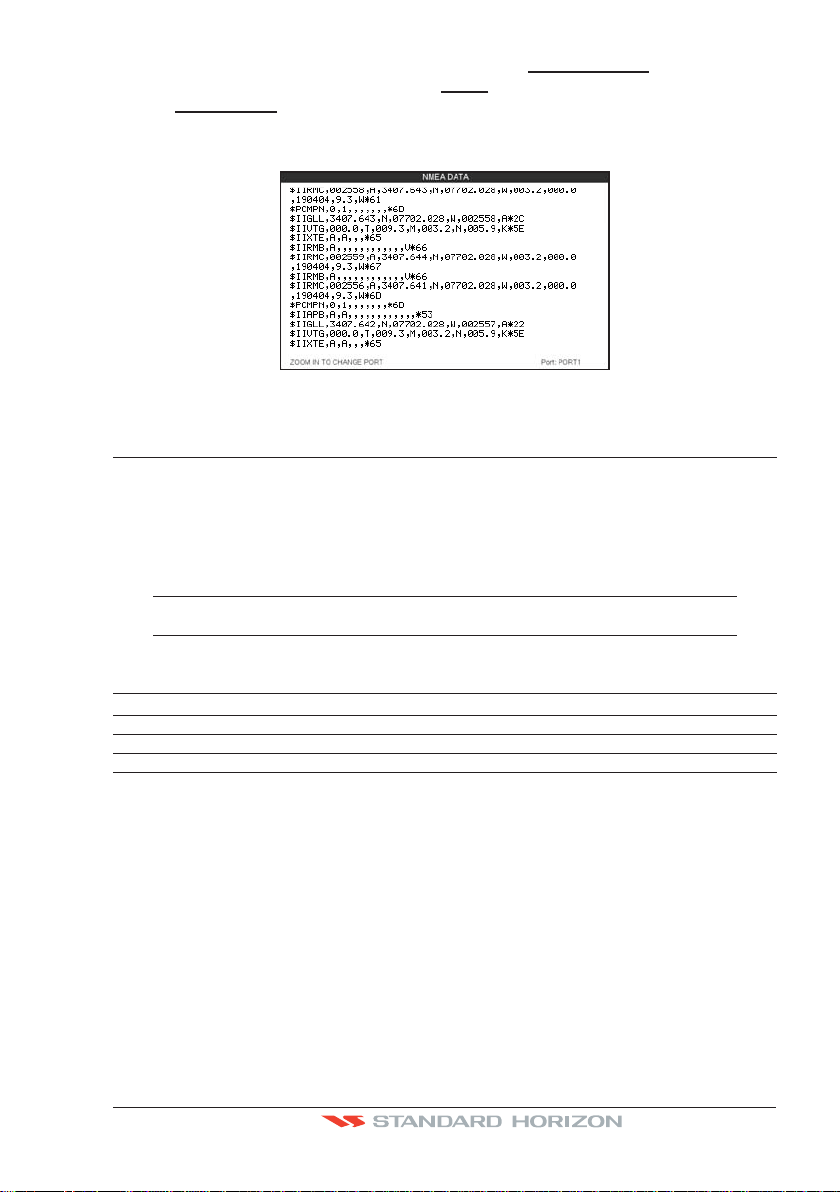
2.11 NMEA DATA PAGE
The NMEA Data page is very useful to see if an external device (example: Depth Sounder)
is transmitting NMEA sentences to the GPS Chart Plotter. This page can also be used to
see if the GPS Chart Plotter NMEA Output is being loaded down by an external NMEA
device the GPS Chart Plotter is connected to. Example: A VHF radio is connected but the
radio is not receiving a GPS Position. Usually the VHF radio will be connected to the Green
and Brown wires. To check to see if the GPS Chart Plotter is transmitting the sentences:
Page 26 CP390i and CPF390i
1. Press [MENU], move the ShuttlePoint knob to highlight NMEA DISPLAY and press [ENT].
2. Move the ShuttlePoint knob to highlight
3. The
NMEA DATA page is shown.
DATA and press [ENT].
4. Connect the Blue Wire on the GPS Chart Plotter to the junction of the Brown wire and
the VHF wire. The display should look similar to the following picture.
Figure 2.11 - NMEA Data page
2.12 CPF300i VIDEO INPUT
By accessing this menu it is possible to see images on the CP390i or CPF390i display from
an external video signal source, if connected to the CP390i or CPF390i.
It allows the "picture-in-picture" functionality, so a Video Input image can be shown on a
window and placed over the Chart, Navigation, Highway, Celestial and NMEA pages image
at full screen.
NOTE
If the Video Input signals is not detected (E.g. the video camera is not connected to the Video Input
connector), the VIDEO INPUT menu item will be grayed out.
Video Connector
Pin Description Connection Example
1 Ground Connect to Video Signal Ground of DVD/VCR/Video Cameras
2 + 9 / 12 VDC Connect to Video Cameras Power Input
3 Video Signal + Connect to Video Signal + (NTSC/PAL) of DVD/VCR/Video Cameras
2.12.0 Video Camera Input
The CP390i or CPF390i has one connection for video camera. Any NTSC or PAL camera
will operate correctly. To connect use the video output of the camera and connect to the
optional ACVC10 cable.
2.12.1 VCR or DVD Input
A VCR or DVD may be connected to Video port. The CP390i or CPF390i does not have
speakers so the audio from the VCR or DVD would have to be routed to a stereo system.
STANDARD HORIZON offers an optional cable called ACVC10 that allows any VCR or
DVD to simply be plugged into the CP390i or CPF390i.
CP390i and CPF390i Page 27

VCR/DVD
Video Signal GND
Video Signal OUT
Audio OUT
Figure 2.12.1 - VCR/DVD Input
STEREO
SYSTEM
VIDEO CONNECTOR
3
2
1
The CP390i or CPF390i has the capability to select the Video Input in three ways.
I. From the menu
1. Press [MENU], move the ShuttlePoint knob to highlight
2. Move the ShuttlePoint knob to highlight
VIDEO INPUT and press [ENT] or move the
SETUP and press [ENT].
ShuttlePoint knob to the right. A menu appears with the following options:
ACTIVATE VIDEO, the possible choices are Full Screen View, PiP (Picture in
a.
Picture) View and Auto Switch (*).
If Full Screen View is chosen, the GPS Chart Plotter will show a warning message
with the instructions to adjust the image from the Video Input. If the user agrees to
proceed, the image from the video input will be shown.
If Picture in Picture (PiP) View is chosen, a Video Input image can be shown on a
window and placed over the selected page at full screen. By moving the ShuttlePoint
knob, the PiP image is moved. When the focus is on the PiP image, press [CLR] to
close the PiP image.
If Auto Switch is chosen, all the menus will be closed and the video input will be
shown switching between the Video Input Full View (if connected) and the selected
page. See next section for details of setting up the switching times. If the user agrees
to proceed, the image from the Video Input and the CP390i or CPF390i page will be
shown intermittently. The intermittence time is selected by Switching Timeout item.
b.
SWITCHING TIMEOUT, the possible choices are 5,10,30 sec, 1, 5, 10 min. Allows
selecting the timing to change from Video Input and CP390i or CPF390i display.
RESTORE DEFAULTS, allows restoring the factory defaults for the Input picture
c.
adjustment. When Restore default is executed, the message “OK” is shown next to
the selected menu item.
NOTE (*)
If the video signal is not present on the video connector, the corresponding item in the menu will
be shown with a light color (to identify that the option is not available).
1=GND
2=PWR+
3=SIGNAL
II. Quick Activation by pressing [CLR] for 1 second
Pressing and holding [CLR] for 1 second from the Chart page Display or from any main page
(Navigation, Highway, Celestial, GPS Status, DSC, NMEA DISPLAY); the following Soft
Keys are shown: [F
ULL SCREEN], [PIP VIEW], [AUTO SWITCH]. If no video signal is detected on
the Video Input connector, the Soft Keys will be shown in light color in order to identify that
they are not active.
III. Quick Activation by Soft Keys
It is possible to assign the Video Input mode to any of the Soft Keys. Press one of the Soft
Keys, the Soft Keys functions are shown. Pressing and holding for 1 second one of the Soft
Keys, the Soft Keys customization list will be shown. By selecting
VIDEO option it will be
possible to assign the Soft Key to execute the Video Input function. Once the Soft Key has
been assigned to Video Input, its label will show the message [V
IDEO]. If [VIDEO] is pressed,
Page 28 CP390i and CPF390i

the Soft Keys will be assigned this way: [FULL SCREEN], [PIP VIEW], [AUTO SWITCH]. From now
on, the functioning is identical to case II.
NOTE
When the PIP video window is shown, the ShuttlePoint knob can be used to move the position of the
PIP window or move the cursor around the Chart page. By default the PIP window is controlled by
the ShuttlePoint knob. To change so the chart cursor can be moved, press any Soft Key, then press
[VIDPAGE]. To change back to control the PIP window press any Soft Key, then press [VIDPAGE] again.
NOTE
When the PIP window is shown, the cursor and the vessels position may be shown under the PIP
window.
2.13 DEMO MODE (FOR DEALER USE)
In Demonstration Mode the GPS Chart Plotter automatically places a Destination point on
the Chart page and simulates navigation to the point. Also, the active page displayed on the
screen changes every 10 seconds. The pages are shown in the following order: Start-up
screen, GPS Status page, Chart/Compass tape page, Chart/Fish Finder page, Fish Finder
Full page, Radar page, Navigation page, Highway Page, Celestial page, NMEA Display
page.
NOTE
This mode is used by dealers to promote the features of the CP390i or CPF390i when on a retail
shelf.
The Demo mode can be selected from the Simulation Menu following the procedure:
1. Press [MENU], move the ShuttlePoint knob to highlight
2. Move the ShuttlePoint knob to highlight
ADVANCED SETUP and press [ENT] or move
the ShuttlePoint knob to the right.
3. Move the ShuttlePoint knob to highlight
SIMULATION and press [ENT] or move the
ShuttlePoint knob to the right.
4. Move the ShuttlePoint knob to highlight
DEMO MODE and press [ENT] or move the
ShuttlePoint knob to the right to show the popup window.
5. Move the ShuttlePoint knob to select
ON and press [ENT] or move the ShuttlePoint
knob to the right.
6. Demo mode is now activated.
SETUP MENU and press [ENT].
Once the Demo Mode is enabled, it is possible to temporally exit Demo Mode by pressing
a key and return to the GPS Chart Plotter normal operation. If a key in not touched for 30
seconds the Demo Mode will re-start.
To disable the Demo Mode follow the procedure above selecting
CP390i and CPF390i Page 29
OFF at point 5.

Page 30 CP390i and CPF390i

3. CONTROLS AND INDICATORS
NOTE
This section defines each control of the CP390i or CPF390i. For instructions, refer to Getting
Started and Advanced Settings sections of this Owner's Manual.
NOTE
Throughout this Owner’s Manual same conventions are used. See the legend below:
[MENU]If you see brackets around a bold and capital letter word this refers to a key press.
[CHART] If you see brackets around a bold and small capital letter word this refers to a Soft Key
press.
GENERAL SETUP When a word(s) is bold capital letters and underlined, this refers to a menu
3.0 CONTROLS AND CONNECTIONS
The CP390i or CPF390i is controlled by using the keys located on the front panel. These
labeled keys are dedicated to specific functions. As you press a key, a single audio beep
confirms the key action; every time a key press is not valid, three rapid beeps sound to
indicate that the key action is not valid. There is also a ShuttlePoint knob to move the cursor
across the screen.
The ZOOM IN and ZOOM OUT keys
Pressing [ZOOM IN] shows more detail of a smaller area, by changing the chart scale and
zooming in on your display. Press [ZOOM OUT] to change the scale and show a wider,
otherwise less detailed view. Pressing and holding [ZOOM IN]/[ZOOM OUT] allows for
quick zoom, that is the fast change of the chart scale where only the land areas are drawn.
When [ZOOM IN]/[ZOOM OUT] is released all chart details are shown.
The GPS Chart Plotter contains a Worldwide background that allows you to zoom in to 2NM. For
more detail, a C-MAP BY JEPPESEN NT+/MAX C-CARD must be purchased and installed.
selection item.
NOTE
The ShuttlePoint knob
The ShuttlePoint knob moves the cursor around the Chart Page (cursor mode) and
highlights menu items. It changes the GPS Chart Plotter from Home mode to Cursor mode
on the Chart Screen. For a detailed explanation of Cursor VS Home mode refer to Par. 3.1.1.
The ENT key
Press [ENT] to select the desired option or to confirm the selection.
The CLR key
When on the Chart Page, press [CLR] to set Home Mode, clear a selected function, leave
a menu, step backwards in a menu or exit a menu.
The MENU key
Selects the Main Menu. When in the Setup Menu mode, moving the ShuttlePoint knob to
the right enters a selection and moving the knob to the left clears the function.
Pressing and holding [MENU] for 3 seconds allows you to change the fields contained within
CP390i and CPF390i Page 31

the data windows while on the Chart, Navigation, Highway, GPS Status or NMEA Display
page.
The GOTO key
This key is very useful when you desire to start navigating (goto) to a destination point. When
pressed, a popup window will be shown allowing you to select to start navigating to the Mark,
a Route or the position of the cursor.
To stop navigation to a point, press [GOTO] and select Stop in the popup window.
The MARK key
This key places a Mark under the ship’s position when in Home Mode. When the cursor is
shown and [MARK] is pressed it will place a Mark under the location of the cursor.
The ROUTE key
When pressed places a Waypoint. Succeeding presses place more Waypoints to form a Route.
The PWR key (Backlight and Contrast)
Press and hold [PWR] to turn the GPS Chart Plotter On or Off. Once on, press [PWR] to
show and change the Contrast and Backlight settings.
The MOB key
When pressed the GPS Chart Plotter automatically places a Mark on the Chart Page under
the boat’s position to aid in the rescue or a person that may have fallen aboard. To stop
navigating, press [GOTO], select
The FIND key
A dedicated key that allows searching the optional C-MAP B
STOP and press [ENT].
Y JEPPESEN NT
+
/MAX C-CARD
for Port Services, Ports, Tide Stations, Wrecks, Obstructions, Points Of Interest, Lakes
Information, Lakes By Name, User Points, GPS Coordinates or Information on any point on
the chart.
3.0.0 The Soft Keys
The 6 keys in the bottom of the front panel (hereinafter named Soft Keys) have different
functions associated depending on the software: their labels are shown on the screen
immediately above the soft keys (the user can customize the function associated with each
soft key).
The Soft Keys
These keys allow quick selection to the many pages the GPS Chart Plotter has. These keys
can be customized to your preference, however from the factory the keys are preprogrammed with the following pages. From left to right VIDEO, NAV, HIGHWAY, CELEST, CHART,
LIST. Press any of the keys and you will see popup windows above the keys. To goto a
specific page press the key with the desired popup window. The popup windows will
automatically disappear if a key is not pressed or can be removed by pressing [CLR].
3.1 GETTING STARTED
The Getting Started section will take you through the frequently used operations and assist
you to customize the look of the GPS Chart Plotter.
Page 32 CP390i and CPF390i
 Loading...