

Page 1
Color GPS Chart Plotters
CP180/CP180i
CP300/CP300i
Owner's Manual
CP300/300i
CP180/180i
Page 2

WARNING!!!
Electronic charts displayed by the GPS Chart Plotter are believed to be accurate and
reliable, but are not intended to be a substitute for the official charts, which should
remain your main reference for all matters related to the execution of safe
navigation.
For this reason we would like to remind you that you should carry on board and use
the official published and approved nautical charts.
FCC Compliance Statement
This device complies with Part 15 of the FCC limits for Class A digital devices. This
equipment generates, uses, and can radiate radio frequency energy and, if not
installed or used in accordance with the instructions may cause harmful interference
with radio communications.
There is no guarantee that interference will not occur in a particular instance. If this
equipment does cause harmful interference to other equipment, try to correct the
problem by relocating the equipment.
Consult an authorized STANDARD HORIZION dealer or other qualified service
technician if the problem cannot be corrected. Operation is subject to the following
conditions: (1) This device cannot cause harmful interference, and (2) this device
must accept any interference received, including interference that may cause
undesired operation.
Copyright 2007. STANDARD HORIZON All rights reserved. Printed in Italy.
OM CODE: S4e/igSH5c_0ww 11.08dA77 & S4e/igSH8wc_0ww 11.12dB33 - 200707
No part of this publication may be reproduced or distributed in any form or by any means, or stored in a database
or retrieval system, without prior written permission of the publisher.
Page 3

CAUTION
- The GPS Chart Plotter is designed for maritime use. To avoid water intrusion
ensure the C-MAP C-CARD door is completely closed.
- Extensive exposure to heat may result in damage to the GPS Chart Plotter.
- The GPS Chart Plotter contains dangerous high voltage circuits which only
experienced technicians can handle.
- STANDARD HORIZON will not be liable for errors contained herein, or for
incidental or consequential damages in connection with the performance or use
of this material.
CLEANING PROCEDURE FOR THE GPS CHART PLOTTER SCREEN
Cleaning of the chart plotter screen is a very important operation and must be done
carefully. Since the surface is covered by a antireflective coating, the procedure for
cleaning all the surfaces can be performed using the following procedure: You need
a tissue or lens tissue and a cleaning spray (Windex) containing Isopropanol (a
normal spray cleaner sold for the PC screen, for example PolaClear by Polaroid).
Fold the tissue or lens tissue into a triangular shape, moisten the tip and use the
index finger behind a corner to move the tissue across the surface, in overlapping
side to side strokes. If the tissue is too wet, a noticeable wet film will be left in its path
and you will need to repeat the process. If too dry, the tissue won’t glide easily, and
may damage the surface.
Page 4

Page 6 GPS Chart Plotters
Page 5

TABLE OF CONTENTS
1. INTRODUCTION ......................................................................................................11
1.0 GENERAL INFORMATION ....................................................................................11
1.1 PACKING LIST ......................................................................................................11
1.1.0 CP180/CP180i Packing List ......................................................................12
1.1.1 CP300/CP300i Packing List ......................................................................12
1.2 OPTIONAL ACCESSORIES ..................................................................................12
2. GETTING STARTED ......................................................................................................13
3. CONTROLS AND INDICATORS ......................................................................................27
4. USING FIND SERVICES & MORE FUNCTION .............................................................. 37
1.2.0 CP300/CP300i Optional Accessories........................................................12
2.0 MOUNTING THE GPS CHART PLOTTER ............................................................ 13
2.1 BRACKET MOUNTING ..........................................................................................13
2.2 CP180 AND CP300 FLUSH MOUNTING .............................................................. 14
2.3 MOUNTING THE CP180 OR THE CP300 EXTERNAL GPS ANTENNA ............. 14
2.3.0 Flush mounting the antenna ...................................................................... 15
2.4 CONNECTIONS .....................................................................................................16
2.4.0 Connection Table For CP180/CP180i .......................................................16
2.4.1 Connection Table For CP300/CP300i .......................................................17
2.4.2 Connection For CP180/CP180i .................................................................18
2.4.3 Connection For CP300/CP300i .................................................................20
2.5 BATTERY CONNECTIONS ................................................................................... 21
2.6 NMEA CONNECTIONS..........................................................................................21
2.7 GPS POSITION ON A VHF RADIO ....................................................................... 22
2.8 OPTIONAL BLACK BOX FISH FINDER ................................................................22
2.9 OUTPUTTING NMEA TO A PERSONAL COMPUTER.........................................22
2.10 NMEA DATA PAGE................................................................................................23
2.11 CP300/CP300i VIDEO INPUT................................................................................23
2.11.0 Video Camera Input ................................................................................... 23
2.11.1 VCR or DVD Input......................................................................................23
2.12 DEMO MODE (For DEALER USE) ........................................................................25
3.0 CONTROLS AND CONNECTIONS .......................................................................27
3.0.0 The CP300/CP300i Soft Keys ...................................................................28
3.1 GETTING STARTED .............................................................................................. 28
3.1.0 Power On, Off and ShuttlePoint knob operation ....................................... 28
3.1.1 Cursor Vs. Home Mode .............................................................................29
3.1.2 Cursor and Menu selection speed.............................................................30
3.1.3 Changing the Ships Icon ........................................................................... 30
3.1.4 Changing the backlight and contrast ......................................................... 31
3.1.5 Selecting North Up or Course Up .............................................................. 31
3.2 ADJUSTING THE TIME ......................................................................................... 32
3.3 SELECTING LORAN TD OR OTHER COORDINATE SYSTEM ..........................33
3.4 CHANGING THE CHART COLOR.........................................................................33
3.5 SELECTING PAGES USING SOFT KEYS ON CP300/CP300i ............................ 34
3.6 CUSTOMIZING THE SOFT KEYS ON CP300/CP300i .........................................34
3.7 OTHER SETTINGS IN GENERAL SETUP MENU ................................................ 35
3.8 INFORMATION PAGE ............................................................................................ 36
4.0 PORT SERVICES...................................................................................................37
4.1 OTHER AVAILABLE SEARCHES..........................................................................37
GPS Chart Plotters Page 7
Page 6

4.2 INFO ON LAKES ....................................................................................................38
4.2.0 Quick Info On Lakes .................................................................................. 38
5. C-MAP MAX OVERVIEW ................................................................................................. 41
6. MAP FUNCTIONS ......................................................................................................43
7. CREATING MARKS ......................................................................................................49
8. MAN OVER BOARD (MOB) FUNCTION .........................................................................55
9. ROUTES ......................................................................................................57
10. TRACKS ......................................................................................................61
11. USER C-CARD ...................................................................................................... 65
12. PAGES ......................................................................................................67
4.2.1 Full Info On Lakes......................................................................................38
5.0 INSERTING THE C-CARD ..................................................................................... 41
6.0 MAX FUNCTIONS MENU ...................................................................................... 43
6.0.0 Zoom Type ................................................................................................. 43
6.0.1 Fonts & Symbols ON THE CP300/CP300i................................................43
6.0.2 Perspective View .......................................................................................44
6.0.3 Dynamic Nav-Aids .....................................................................................44
6.0.4 Safety Status Bar (DSI - Data Safety Indicator)........................................45
6.0.5 Currents Prediction .................................................................................... 46
6.0.6 Pictures & Diagrams .................................................................................. 46
How to show the pictures or diagrams of a Multimedia Object.................47
6.0.7 Enhanced Port Info .................................................................................... 48
7.0 CREATING A NEW MARK USING THE CHART PAGE ....................................... 49
7.1 EDITING a MARK ................................................................................................... 49
7.1.0 Deleting a Mark or Waypoint .....................................................................50
7.1.1 Moving a Mark or Waypoint ....................................................................... 50
7.2 MARKS/WAYPOINTS LIST ...................................................................................51
7.3 CREATING A NEW MARK WITH THE USER POINTS LIST ...............................52
7.4 GOTO CURSOR.....................................................................................................52
7.5 GOTO MARK ...................................................................................................... 53
8.0 DELETING A MOB POINT ..................................................................................... 55
9.0 CREATING A ROUTE USING WAYPOINTS ........................................................57
9.1 MAKING ADDITIONAL ROUTES...........................................................................58
9.2 CREATING A ROUTE USING MARKS ON THE CHART PAGE .......................... 58
9.3 INSERTING A WAYPOINT INTO A ROUTE .........................................................59
9.4 GOTO A ROUTE ....................................................................................................59
9.4.0 By select Route..........................................................................................59
9.4.1 By Cursor key ............................................................................................ 59
9.5 OTHER SETTINGS IN ROUTE MENU .................................................................. 59
10.0 TRACKING ......................................................................................................61
10.0.0 Saving and starting a new Track ...............................................................62
10.0.1 Other Settings in Track Menu....................................................................62
10.1 USING THE TRIP LOG ..........................................................................................62
10.1.0 Resetting the Trip Log ...............................................................................63
11.0 USER C-CARD MENU ...........................................................................................65
11.0.0 Formatting the User C-CARD .................................................................... 65
11.0.1 Transferring files to the optional User C-CARD ........................................65
11.0.2 Loading a file..............................................................................................66
11.0.3 Deleting a file from the User C-CARD.......................................................66
11.0.4 Refreshing the User C-CARD....................................................................66
12.0 CHART PAGE ...................................................................................................... 68
12.0.0 Window Selections ....................................................................................68
12.0.1 Additional Functions on Chart page ..........................................................69
Page 8 GPS Chart Plotters
Page 7

12.0.2 Turning Off Information on Icon Points .....................................................69
12.0.3 Display Mode .............................................................................................69
12.0.4 Marine Settings .......................................................................................... 70
12.0.5 Depth Settings ...........................................................................................71
12.0.6 Land Settings ............................................................................................. 71
12.0.7 Chart Settings ............................................................................................71
12.0.8 Underwater Objects Settings ..................................................................... 71
12.0.9 Customizing the Data Windows ................................................................72
12.1 CUSTOMIZING CHART SETTINGS ...................................................................... 72
12.2 NAVIGATION PAGE .............................................................................................. 72
12.3 HIGHWAY PAGE ................................................................................................... 73
12.4 CELESTIAL PAGE .................................................................................................74
12.5 GPS STATUS PAGE ..............................................................................................74
12.6 NMEA DISPLAY PAGE .......................................................................................... 75
12.7 NMEA DATA PAGE................................................................................................75
12.8 NMEA DEPTH, WIND SPEED, TEMP AND SOG TREND PAGES......................76
12.9 VHF DIGITAL SELECTIVE CALLING .................................................................... 76
12.9.0 Interfacing ..................................................................................................76
12.9.1 DSC Distress Call ...................................................................................... 77
13. ADVANCED SETTINGS ...................................................................................................79
14. AIS ......................................................................................................83
15. C-MAP WEATHER SERVICE...........................................................................................87
16. TROUBLE SHOOTING.....................................................................................................89
17. TECHNICAL TESTS ......................................................................................................91
18. SPECIFICATIONS ......................................................................................................93
19. APPENDIX: TERMS ......................................................................................................97
ANALITYCAL INDEX ...................................................................................................... 99
12.9.2 Position Request........................................................................................77
13.0 INPUT/OUTPUT (NMEA) .......................................................................................79
13.1 NAVIGATE ...................................................................................................... 79
13.2 COMPASS ......................................................................................................80
13.3 ALARMS ...................................................................................................... 80
14.0 AIS SYSTEM DEFINITIONS .................................................................................. 83
14.1 AIS MENU ......................................................................................................84
14.2 TO SET THE CHART PLOTTER FOR RECEIVING AIS ......................................84
14.3 QUICK INFO ON AIS TARGET..............................................................................85
15.0 C-MAP WEATHER SERVICE MENU ....................................................................87
15.0.0 Download ...................................................................................................87
15.0.1 Copy From User C-CARD ......................................................................... 88
15.0.2 Weather Forecast ......................................................................................88
15.0.3 Real Time View..........................................................................................88
15.0.4 Type of Data .............................................................................................. 88
17.0 SYSTEM TEST ......................................................................................................91
17.0.0 RAM Menu (reset)......................................................................................91
17.0.1 DIM Menu...................................................................................................91
17.0.2 Cartridges...................................................................................................92
17.0.3 Serial Ports ................................................................................................ 92
18.0 CP180/CP180i SPECIFICATIONS ......................................................................... 93
18.1 CP300/CP300i SPECIFICATIONS ......................................................................... 94
18.2 GPS WAAS SMART Receiver Specifications........................................................95
GPS Chart Plotters Page 9
Page 8

Page 10 GPS Chart Plotters
Page 9

1. INTRODUCTION
Congratulations on your purchase of the Standard Horizon GPS Chart Plotter. Whether this
is your first GPS Chart Plotter, or if you have other STANDARD HORIZON equipment, the
STANDARD HORIZON organization is committed to ensuring your enjoyment of this GPS
Chart Plotter. STANDARD HORIZON technical support personnel stand behind every
product we sell, and our Product Support team invites you to contact us should you require
technical advice or assistance, at 800/767-2450, or marinetech@vxstdusa.com.
1.0 GENERAL INFORMATION
The CP180, CP300 (with external GPS antenna) and CP180i, CP300i (with internal GPS
antenna) are precision-crafted GPS Chart Plotters with high-performance receiver for the
Global Positioning System (WAAS GPS) constellation of satellites, providing precise
location data with a host of navigation features. Ideal for nautical use and sealed against
water ingress. The GPS Chart Plotter is housed in a rugged, impact-resistant case with
outstanding ergonomic design, for effortless operation.
The advanced features of the GPS Chart Plotter include:
· Direct sunlight viewable color LCD display
· Capable of using the Optional FF520 50/200kHz BLACK BOX FISH FINDER
· C-MAP NT+/MAX cartography compatible
· Improved Worldwide background showing detail up to 2.0 NM
· GPS WAAS Smart Antenna, bracket and flush mounting hardware (FOR CP180 AND
CP300 ONLY)
· for CP180/CP180i: 600 Waypoints (Marks) / 20 Routes storage
for CP300/CP300i: 3000 Waypoints (Marks) / 50 Routes storage
· User selectable data fields
· NMEA Data pages
· for CP180/CP180i: 3 NMEA Outputs and 2 Inputs (2 Inputs for CP180i)
for CP300/CP300i: 5 NMEA Outputs and 3 Inputs (2 Inputs for CP300i)
· Connections to and from STANDARD HORIZON DSC VHF’s for Distress and Position
Request calls
· 3 year limited warranty, lifetime flat rate
NOTE
The screen imagines on this manual refer to the CP180/CP180i Chart Plotters unless specified.
1.1 PACKING LIST
When the package containing the GPS Chart Plotter is first opened, please check for the
following contents.
If any parts are missing contact the dealer this GPS Chart Plotter was purchased from.
Accessories and replacement parts may be ordered from STANDARD HORIZON’s Parts
Department at 767/827-7600 ext 6800 or email at yaesuparts@vxstdusa.com.
GPS Chart Plotters Page 11
Page 10

1.1.0 CP180/CP180i Packing List
PART CODE ITEM
S8002224A External bracket
S8002225 Mounting knob with two washers
S8002222 Dust cover
T9101553 Power data cable
S8002223 Flush mounting screws (CP180 ONLY)
EM016N550 Flush mount template (CP180 ONLY)
XUCMP0058 GPS WAAS Smart antenna
EM023U100 Owner’s Manual
EM023U500 Quick Reference Guide
1.1.1 CP300/CP300i Packing List
PART CODE ITEM
S8002224A External bracket
S8002225 Mounting knob with two washers
S8002235 Dust cover
T9101553 PWR & ACC 1 cable
T9101553 ACC 2 cable
S8002223 Flush mounting screws (CP300 ONLY)
EM022U500 Flush mount template (CP300 ONLY)
XUCMP0052 2 Amp fuse and holder
XUCMP0058 GPS WAAS Smart antenna (CP300 ONLY)
EM022U100 Owner’s Manual
EM022U510 Quick Reference Guide
1.2 OPTIONAL ACCESSORIES
1.2.0 CP300/CP300i Optional Accessories
PARTS NAME ITEM
ACVC10 Video Adapter cable (AAF69X001)
FF520 50/200kHz Black Box Fish Finder
DST520 500W 2" Nylon thru hull depth temp Transducer
DST521 500W Transom mount depth, speed temp Transducer
DST523 500W 2" Bronze thru hull depth temp Transducer
DST525 500W In-Hull Transducer
DST526 500W 2" Bronze thru hull depth, speed temp Transducer
DST527 1000W In-Hull depth Transducer
DST528 1000W Bronze long stem depth temp Transducer
Page 12 GPS Chart Plotters
Page 11
2. GETTING STARTED
NOTE
Throughout this Owner’s Manual same conventions are used. See the legend below:
[MENU]If you see brackets around a bold and capital letter word this refers to a key press.
[CHART] If you see brackets around a bold and small capital letter word this refers to a Soft Key
press.
GENERAL SETUP When a word(s) is bold capital letters and underlined, this refers to a menu
2.0 MOUNTING THE GPS CHART PLOTTER
The CP180 and CP300 are supplied with hardware for bracket or flush mounting, the
CP180i and CP300i are is supplied with the hardware for bracket mounting due to the
internal design of the GPS antenna. Below are pictures showing actual examples of the two
types of installation.
The GPS Chart Plotter with internal GPS antenna is designed to be bracket mounted only. Do not
flush mount or GPS performance may be dramatically reduced or not receive a fix.
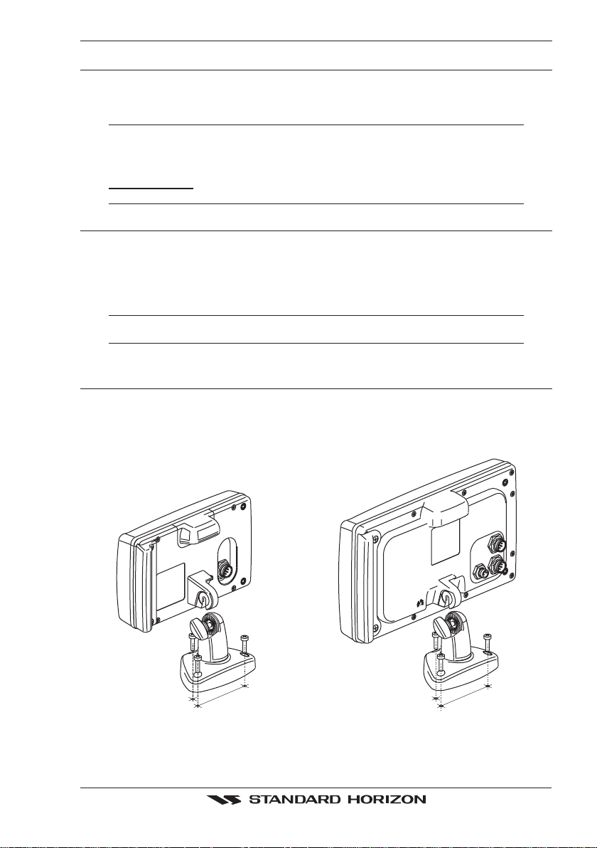
2.1 BRACKET MOUNTING
The CP180/CP180i and CP300/CP300i can be mounted using the supplied swivel mounting
bracket. Before installing ensure the area the bracket is mounted to is strong enough to
support the weight of the GPS Chart Plotter especially while under way.
After the location is found, attach the mounting base to the area using the supplied hardware.
selection item.
NOTE
Figure 2.1 - Example of Bracket installation (CP180i on the left side and CP300i on the right side)
GPS Chart Plotters Page 13
Page 12
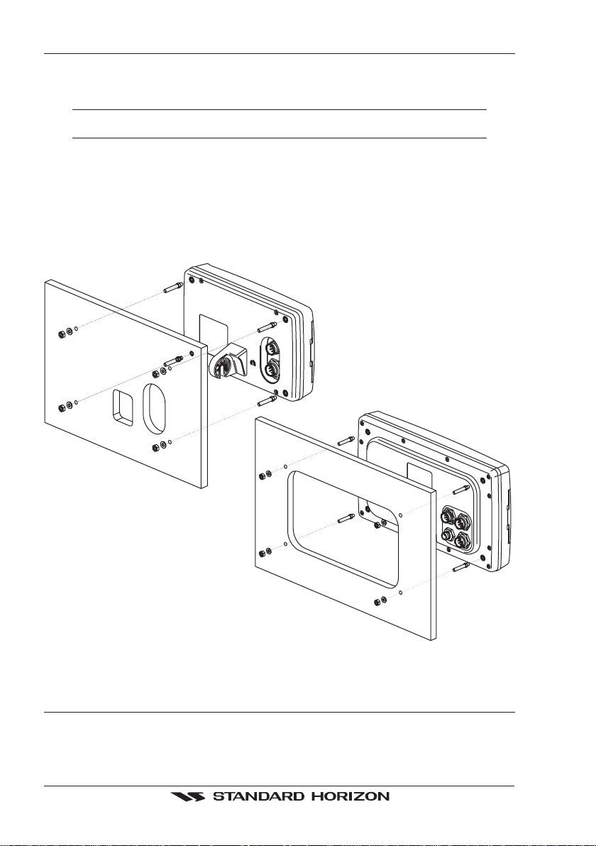
2.2 CP180 AND CP300 FLUSH MOUNTING
The CP180 and CP300 are supplied with a flush mount template for the cutout hole and
screw holes required to install the GPS Chart Plotter.
NOTE
Before drilling holes make sure there is enough room to mount the GPS Chart Plotter and there
are no obstructions.
1. After a location is found, peel the template label from the backing and apply the label
to the mounting area.
2. Drill a hole in one area of the cutout area that will allow the blade of a jig saw to be
inserted. Insert and cut out the area on the panel using the jig saw.
3. Next drill the four holes required to insert the GPS Chart Plotter with the mounting studs.
4. Install the mounting studs on the GPS Chart Plotter and insert into the mounting hole.
5. Attach the GPS Chart Plotter to the mounting location by attaching the supplied
hardware to the mounting studs.
Figure 2.2 - Example of Flush installation (CP180 on the left side and CP300 on the right side)
2.3 MOUNTING THE CP180 OR THE CP300 EXTERNAL GPS
ANTENNA
The CP180 and CP300 are supplied with a external GPS WAAS antenna with 30 feet of
routing cable. This antenna is designed to be mounted on a base, installed on an extension
or even flush mounted.
Page 14 GPS Chart Plotters
Page 13
Choose a location for the antenna that has a clear view of the sky and is not located within
CUTTING TEMPLATE
3 FT of Radar or other transmitting antennas. Ensure there are no major obstructions or
fixtures in the immediate proximity to the antenna. The antenna relies on direct “line of sight”
satellite reception. If you are unsure of the chosen location, temporarily mount the antenna
in the desired location to verify correct operation. If mounted close to Radar, after the GPS
Chart Plotter has a fix, turn on the Radar to ensure the GPS Chart Plotter holds the fix (use
the GPS Status Page).
The thread used on the antenna is an industry standard (1inch 14TPI) used on a wide range
of mounting brackets. Due to the manufacturing process of these mounting brackets, the
antenna may not tighten all the way down onto all the threads. This is no concern however
as the antenna must be tightened until the antenna stops rotating.
NOTE
The antenna cable can be cut and spliced to ease installation. Care must be taken when
reconnecting the antenna cable to protect from water and corrosion.
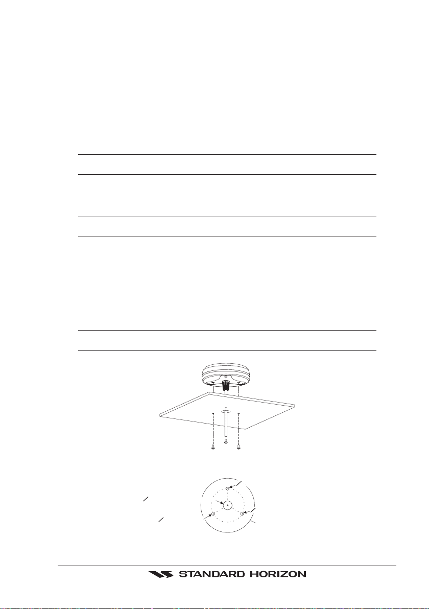
2.3.0 Flush mounting the antenna
NOTE
Before drilling holes, it is recommended the antenna be positioned where the location is planned,
cable connected to the GPS Chart Plotter and power turned on to ensure a GPS Fix is received.
1. Remove the threaded base from the antenna dome.
2. To ease installation a flush mounting template for the antenna has been included.
3. Apply the mounting template sticker to the area that was verified for GPS reception.
4. Then, drill out the 0.63” (16mm) and 0.16” (4mm) holes, and remove the template.
5. Insert the cable into the 0.63” (16mm) hole and route to the GPS Chart Plotter.
6. Apply a small amount or RTV to the under side of the antenna.
7. Place the antenna and then screw it into place using the screws.
NOTE
In some cases the screw may not be long enough, if this happens simply apply more RTV to the
underside of the antenna to glue it into place.
Figure 2.3.0 - Installing the GPS WAAS Smart Antenna (I)
4 mm [0.155"]
0
16 mm [0.63"] or greater
0
4 mm [0.155"]
4 mm [0.155"]
0
GPS Chart Plotters Page 15
Figure 2.3.0a - Installing the GPS WAAS Smart Antenna (II)
0
GPS OVERALL SHAPE
Page 14

2.4 CONNECTIONS
The GPS Chart Plotter has connectors that are used to connect to the power supply, GPS
Antenna (CP180
and to NMEA devices such as VHF’s, AIS Receivers, digital instruments and autopilots.
The GPS Chart Plotter can send many sentences to external NMEA devices. The NMEA Output
wires are Yellow, Brown and White. If you have connected devices as shown in the below table and
need to feed NMEA to other devices (Autopilot, RADAR…) you can parallel wires from the Yellow,
Brown or White wires.
AND CP300 ONLY) optional FF520 50/200kHz BLACK BOX FISH FINDER
NOTE
2.4.0 Connection Table For CP180/CP180i
12VDC Power and NMEA PWR & ACC 1 Cable
Pin Wire Color Description Connection Example Additional Comments
1 Black Battery Ground Connect to Battery Ground
2 Red Battery Positive Connect to Battery Positive
3 Green NMEA Common Common (ground) for NMEA devices
4 Blue Port1 Input Connect to Output of NMEA device Default is NMEA0183*
5 Brown Port1 Output Connect to Input of NMEA device Default is NMEA0183 with GLL, RMB, RMC
6 Gray Port2 Input Connect to Output of NMEA device Default is NMEA0183**
7 White Port2 Output Connect to Input of NMEA device Default is NMEA0183 with GLL, RMB, RMC
8 Yellow Port3 Output Connect to Output of NMEA device Default is NMEA0183 with APA, APB, XTE,
*NOTE: AIS RECEIVER OPTION
When an optional AIS rceiver is connected, Port 1 of the NMEA in/out Communication setup
menu must be changed to AIS 38400 as shown below for communications.
1. From the Chart page, press [MENU]. Move the ShuttlePoint knob to highlight
MENU and press [ENT].
2. Move the ShuttlePoint knob to highlight
ADVANCED SETUP and press [ENT] or move
the ShuttlePoint knob to the right.
3. Move the ShuttlePoint knob to highlight
IN/OUT CONNECTIONS and press [ENT] or
move the ShuttlePoint knob to the right.
4. Move the ShuttlePoint knob to highlight
PORT 1 INPUT and press [ENT] or move the
ShuttlePoint knob to the right.
5. Move the ShuttlePoint knob up/down to select
ShuttlePoint knob to the right.
6. Press [CLR] or move the ShuttlePoint knob to the left until the Chart page is shown.
**NOTE: FF520 FISH FINDER OPTION
When a FF520 is connected to the GPS Chart Plotter, Port 2 of the NMEA in/out Communication setup menu must be changed to FF520 as shown below for communications.
1. From the Chart page, press [MENU]. Move the ShuttlePoint knob to highlight
MENU and press [ENT].
2. Move the ShuttlePoint knob to highlight
ADVANCED SETUP and press [ENT] or move
the ShuttlePoint knob to the right.
3. Move the ShuttlePoint knob to highlight
IN/OUT CONNECTIONS and press [ENT] or
move the ShuttlePoint knob to the right.
4. Move the ShuttlePoint knob to highlight
PORT 2 INPUT and press [ENT] or move the
ShuttlePoint knob to the right.
and XTE sentences
and XTE sentences
COG and BOD sentences***
SETUP
AIS 38400 and press [ENT] or move the
SETUP
Page 16 GPS Chart Plotters
Page 15

5. Move the ShuttlePoint knob up/down to select FF520 and press [ENT] or move the
ShuttlePoint knob to the right.
6. Press [CLR] or move the ShuttlePoint knob to the left until the Chart page is shown.
***NOTE: AUTOPILOT CONNECTION
Care must be taken when connecting the GPS Chart Plotter to an autopilot. Normally Port
3 (Yellow wire) will be used to connect to an Autopilot input, however older autopilots may
not be able to read the sentences due to the talker ID that is being used (II Integrated
Instrument). If the autopilot connections are made to Port 3 (Yellow wire) and the autopilot
is not reading the sentences, change the connections to Port 1 (Brown) or 2 (White) and
change the sentences to APA, APB, XTE, COG and BOD.
Smart GPS Cable
Pin Wire Color Description
1 Red Battery Positive
2 Green Smart GPS NMEA Output
3 Brown Smart GPS NMEA Input
4NC
5NC
6 Black/Yellow Battery Ground
FOR CP180 and CP300
2.4.1 Connection Table For CP300/CP300i
12VDC Power and NMEA PWR & ACC 1 Cable
Pin Wire Color Description Connection Example Additional Comments
1 Black Battery Ground Connect to Battery Ground
2 Red Battery Positive Connect to Battery Positive
3 Green NMEA Common Common (ground) for NMEA devices
4 Blue Port 1 Input Connect to Output of NMEA device Default is NMEA0183
5 Brown Port 1 Output Connect to Input of NMEA device Default is NMEA0183 with GLL, RMB, RMC
6 Gray Port 2 Input Connect to Output of NMEA device Default is NMEA0183*
7 White Port 2 Output Connect to Input of NMEA device Default is NMEA0183 with GLL, RMB, RMC
8 Yellow Port 3 Output Connect to Output of NMEA device Default is NMEA0183 with APA, APB, XTE,
*NOTE: FF520 FISH FINDER OPTION
When a FF520 is connected to the GPS Chart Plotter, Port 2 of the NMEA in/out Communication setup menu must be changed to FF520 as shown below for communications.
1. From the Chart page, press [MENU]. Move the ShuttlePoint knob to highlight
MENU and press [ENT].
2. Move the ShuttlePoint knob to highlight
ADVANCED SETUP and press [ENT] or move
the ShuttlePoint knob to the right.
3. Move the ShuttlePoint knob to highlight
IN/OUT CONNECTIONS and press [ENT] or
move the ShuttlePoint knob to the right.
4. Move the ShuttlePoint knob to highlight
PORT 2 INPUT and press [ENT] or move the
ShuttlePoint knob to the right.
5. Move the ShuttlePoint knob up/down to select
ShuttlePoint knob to the right.
6. Press [CLR] or move the ShuttlePoint knob to the left until the Chart page is shown.
and XTE sentences
and XTE sentences
COG and BOD sentences
SETUP
FF520 and press [ENT] or move the
GPS Chart Plotters Page 17
Page 16
NMEA ACC 2 Cable
Pin Wire Color Description Connection Example Additional Comments
1 Black NC
2 Red NC
3 Green NMEA Common Common (ground) for NMEA devices
4 Blue Port 4 Input Connect to Output of NMEA device Default is NMEA0183**
5 Brown Port 4 Output Connect to Input of NMEA device Default is NMEA0183 with GLL, RMB, RMC
6 Gray Port 5 Input Connect to Output of NMEA device Default is NMEA0183
7 White Port 5 Output Connect to Input of NMEA device Default is NMEA0183 with GLL, RMB, RMC
8 Yellow NC
**NOTE: AIS RECEIVER OPTION
and XTE sentences
and XTE sentences
When an optional AIS rceiver is connected, Port 4 of the NMEA in/out Communication setup
menu must be changed to AIS 38400 as shown below for communications.
1. From the Chart page, press [MENU]. Move the ShuttlePoint knob to highlight
SETUP
MENU and press [ENT].
2. Move the ShuttlePoint knob to highlight
ADVANCED SETUP and press [ENT] or move
the ShuttlePoint knob to the right.
3. Move the ShuttlePoint knob to highlight
IN/OUT CONNECTIONS and press [ENT] or
move the ShuttlePoint knob to the right.
4. Move the ShuttlePoint knob to highlight
PORT 4 INPUT and press [ENT] or move the
ShuttlePoint knob to the right.
5. Move the ShuttlePoint knob up/down to select
AIS 38400 and press [ENT] or move the
ShuttlePoint knob to the right.
6. Press [CLR] or move the ShuttlePoint knob to the left until the Chart page is shown.
Video Connector
Pin Description Connection Example
1 Ground Connect to Video Signal Ground of DVD/VCR/Video Cameras
2 + 9 / 12 VDC Connect to Video Cameras Power Input
3 Video Signal + Connect to NTSC Video Signal + of DVD/VCR/Video Cameras
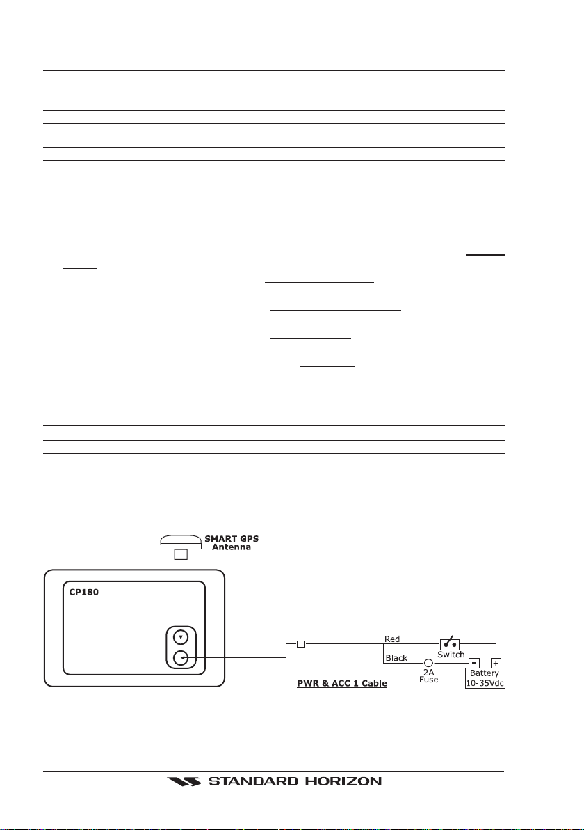
2.4.2 Connection For CP180/CP180i
2.4.2.1 DC Power Connection
Page 18 GPS Chart Plotters
Page 17
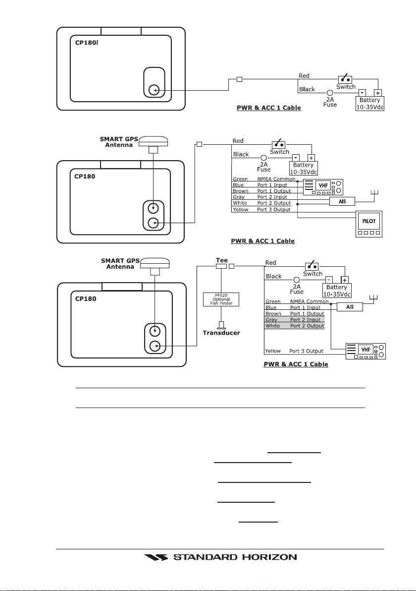
2.4.2.2 Connection of the FF520, AIS receiver, VHF and Autopilot
NOTE
Port 2 input and output is used by the optional FF520. In the diagram above you will notice Port 2
Input and Output wires are shown in gray and not used.
AIS Setup
The CP180 or CP180i has to be setup to be able to receive NMEA information from the AIS
receiver.
1. Press [Menu], move the ShuttlePoint knob to highlight
2. Move the ShuttlePoint knob to highlight
ADVANCED SETUP and press [ENT] or move
SETUP MENU and press [ENT].
the ShuttlePoint knob to the right.
3. Move the ShuttlePoint knob to highlight
IN/OUT CONNECTIONS and press [ENT] or
move the ShuttlePoint knob to the right.
4. Move the ShuttlePoint knob to highlight
PORT 1 INPUT and press [ENT] or move the
ShuttlePoint knob to the right.
5. Move the ShuttlePoint knob up/down to select
AIS 38400 and press [ENT] or move the
ShuttlePoint knob to the right.
GPS Chart Plotters Page 19
Page 18
NOTE
If an AIS receiver is not connected, Port 1 Input can be connected to most DSC VHF’s for position
polling.
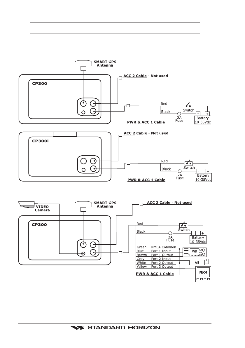
2.4.3 Connection For CP300/CP300i
2.4.3.1 DC Power Connection
2.4.3.2 Connection a VideoCamera, FF520, AIS receiver, VHF and Autopilot
Page 20 GPS Chart Plotters
Page 19
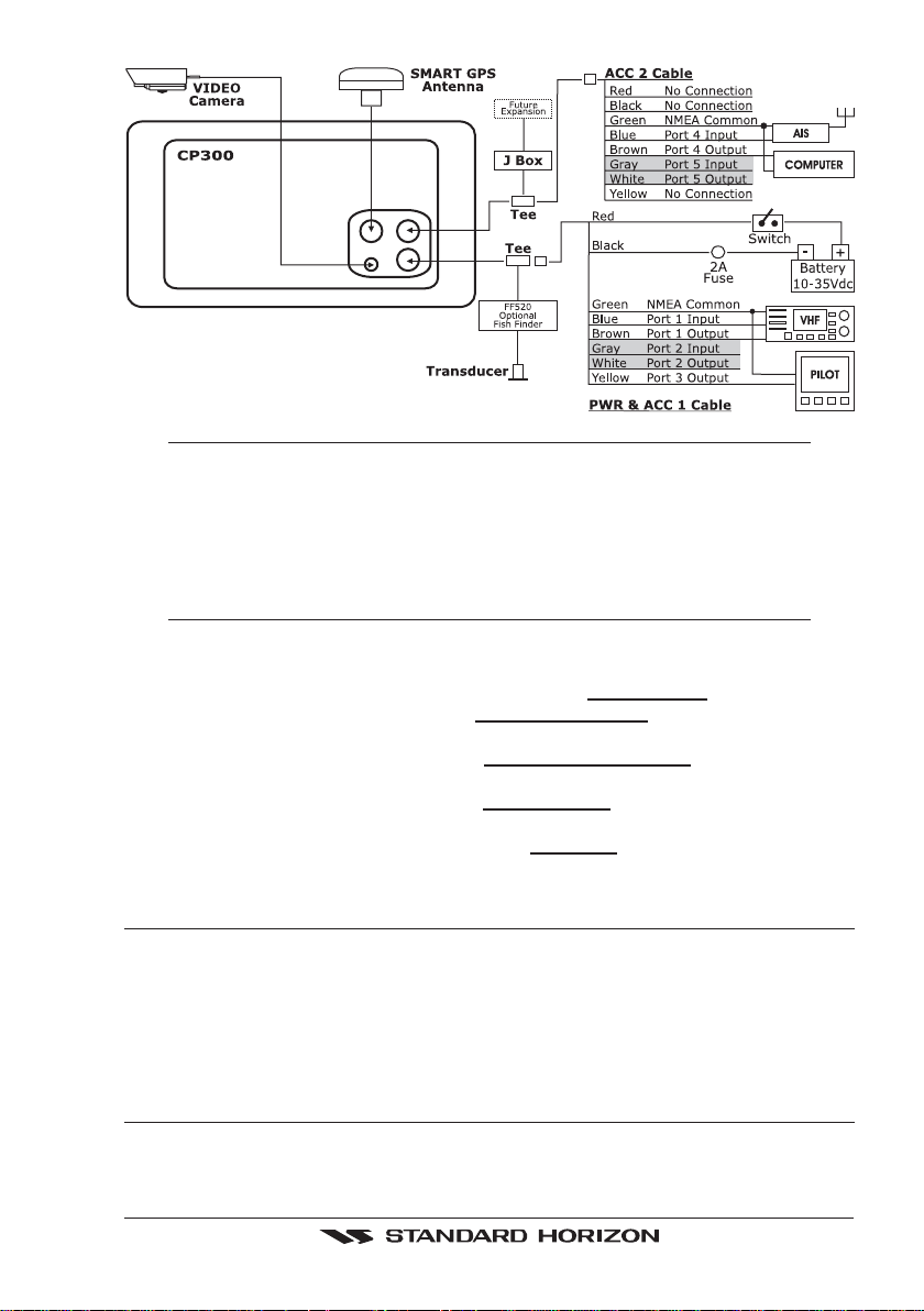
NOTE
Port 2 Input and Output is used by the optional FF520. In the diagram above you will notice Port
2 Input and Output wires are shown in gray and not used.
Port 4, and 5 Outputs are can be connected to NMEA devices capable of listening to NMEA 0183
sentences.
Port 4, and 5 Inputs can be connected to NMEA devices capable of outputting to NMEA 0183
sentences.
The Input and Output baud rate for each port are set using the Advanced
Setup>In/Out Connections menu. For example if Port 1 is set for AIS 38400, the
Input and Output both operate at 38400 baud.
AIS Setup
The CP300 or CP300i has to be setup to be able to receive NMEA information from the AIS receiver.
1.Press [Menu], move the ShuttlePoint knob to highlight
2. Move the ShuttlePoint knob to highlight
ADVANCED SETUP and press [ENT] or move
SETUP MENU and press [ENT].
the ShuttlePoint knob to the right.
3. Move the ShuttlePoint knob to highlight
IN/OUT CONNECTIONS and press [ENT] or
move the ShuttlePoint knob to the right.
4. Move the ShuttlePoint knob to highlight
PORT 4 INPUT and press [ENT] or move the
ShuttlePoint knob to the right.
5. Move the ShuttlePoint knob up/down to select
AIS 38400 and press [ENT] or move the
ShuttlePoint knob to the right.
2.5 BATTERY CONNECTIONS
1. The GPS Chart Plotters are supplied with a fuse and holder. This fuse should be
installed into the Black wire to protect the NMEA Output/Input circuits from becoming
damaged.
2. Connect the Red and Black wires from the GPS Chart Plotter to a 12VDC source directly
as possible.
2.6 NMEA CONNECTIONS
The GPS Chart Plotter can be connected to external devices with NMEA and display
information, examples:
GPS Chart Plotters Page 21
Page 20
- DSC VHF Radio
- Depth Sounder, Speed Log, Wind Instrument, Autopilot etc.
- Personal Computer
- AIS receiver
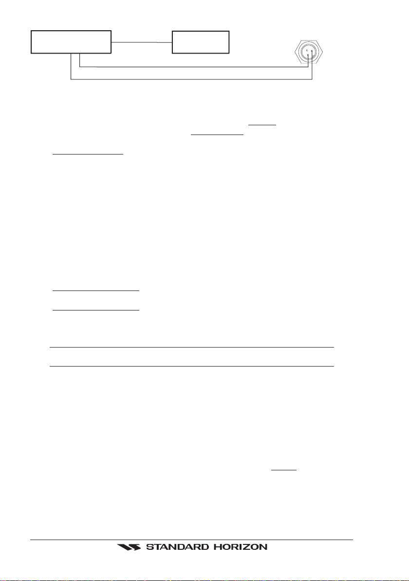
2.7 GPS POSITION ON A VHF RADIO
STANDARD HORIZON has pioneered Digital Selective Calling (DSC) on VHF radios.
Advancements in DSC have made it possible to show the coordinates of a vessel that has
transmitted a DSC Distress Call or even Poll the location of another vessel and show the
position of that vessel on the display of STANDARD HORIZON VHFs.
STANDARD HORIZON has taken this feature one step further, if the GPS Chart Plotters
are connected to a STANDARD HORIZON DSC capable VHF, the vessel in Distress or the
polled position of the vessel is shown on the display of the GPS Chart Plotter, making it easy
to navigate to the location of the vessel. This is a great feature that could save someone’s
life or for anyone wanting to know the position of another vessel.
Other DSC VHF Manufactures
GPS Chart Plotter Description VHF
Green NMEA Common Ground Connect to NMEA Ground
Brown NMEA Positive Output Connect to NMEA Input
Blue NMEA Positive Input * Connect to NMEA Output (if available)
* Some manufacturers of DSC VHF’s are not capable of receiving NMEA DSC sentences from the GPS
Chart Plotter. Refer to the Owner’s Manual and confirm the VHF can receive NMEA DSC and DSE
sentences output by the brown wire.
NOTE
Refer to VHF Digital Selective Calling section for operation.
2.8 OPTIONAL BLACK BOX FISH FINDER
STANDARD HORIZON offers an optional BLACK BOX FISH FINDER called the FF520. Please
refer to the Owner's Manual supplied with the Fish Finder for connections and operation.
Figure 2.8 - FF520 50/200kHz BLACK BOX FISH FINDER
2.9 OUTPUTTING NMEA TO A PERSONAL COMPUTER
The GPS Chart Plotter can be connected to output Marks, Routes and tracks to many PC
programs available. To send or receive User Points the PC Program must be able to receive
NMEA WPL and RTE sentences. Refer to the table below for connection to a Serial DB9
connector.
Pin PC DB9 connection NMEA connection
2 Receive Brown
3 Transmit Blue
5 Signal ground Green
Page 22 GPS Chart Plotters
Page 21
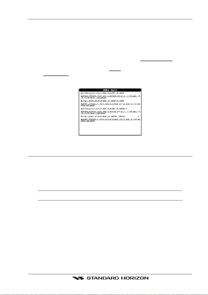
2.10 NMEA DATA PAGE
The NMEA Data Page is very useful to see if a External device (example: Depth Sounder)
is transmitting NMEA sentences to the GPS Chart Plotter. This page can also be used to
see if the GPS Chart Plotter NMEA output is being loaded down by a external NMEA device
the GPS Chart Plotter is connected to. Example:
VHF Radio connected but the radio is not receiving a GPS Position.
Usually the VHF radio will be connected to the Green and Brown wires. To check to see if
the GPS Chart Plotter is transmitting the sentences:
1. Press [MENU]. Move the ShuttlePoint knob to highlight
NMEA DISPLAY and press
[ENT].
2. Move the ShuttlePoint knob to highlight
3. The
NMEA DATA page is shown.
DATA and press [ENT].
4. Connect the Blue Wire on the GPS Chart Plotter to the junction of the Brown wire and
the VHF wire. The display should look similar to the picture below.
ENTER TO STOP
ZOOM IN TO CHANGE Port: NMEA1
Figure 2.10 - NMEA Data page
2.11 CP300/CP300i VIDEO INPUT
By accessing this menu it is possible to see images on the CP300/CP300i display from an
external video signal source, if connected to the CP300/CP300i.
It allows the "picture-in-picture" functionality, so a Video Input image can be shown on a
window and placed over the Chart, Navigation, Highway, Celestial and NMEA pages image
at full screen.
NOTE
If the Video Input signals is not detected (E.g. the video camera is not connected to the Video Input
connector), the VIDEO INPUT menu item will be grayed out.
2.11.0 Video Camera Input
The CP300/CP300i has one connection for video camera. Any NTSC or PAL camera will
operate correctly. To connect use the video output of the camera and connect to the optional
ACVC10 cable.
2.11.1 VCR or DVD Input
A VCR or DVD may be connected to Video port. The CP300/CP300i does not have speakers
so the audio from the VCR or DVD would have to be routed to a stereo system.
STANDARD HORIZON offers an optional cable called ACVC10 that allows any VCR or
DVD to simply be plugged into the CP300/CP300i.
GPS Chart Plotters Page 23
Page 22
VCR/DVD
Video Signal GND
Video Signal OUT
Audio OUT
Figure 2.11.1 - VCR/DVD Input
STEREO
SYSTEM
VIDEO CONNECTOR
2
The CP300/CP300i has the capability to select the Video Input in three ways.
I. From the menu
1. Press [MENU]. Move the ShuttlePoint knob to highlight
2. Move the ShuttlePoint knob to highlight
VIDEO INPUT and press [ENT] or move the
SETUP and press [ENT].
ShuttlePoint knob to the right. A menu appears with the following options:
a.
ACTIVATE VIDEO, the possible choices are Full Screen View, PiP (Picture in
Picture) View and Auto Switch (*).
If Full Screen View is chosen, the GPS Chart Plotter will show a warning message
with the instructions to adjust the image from the Video Input. If the user agrees to
proceed, the image from the video input will be shown.
If Picture in Picture (PiP) View is chosen, a Video Input image can be shown on a
window and placed over the selected page at full screen. By moving the ShuttlePoint
knob, the PiP image is moved. When the focus is on the PiP image, press [CLR] to
close the PiP image.
If Auto Switch is chosen, all the menus will be closed and the video input will be
shown switching between the Video Input Full View (if connected) and the selected
page. See next section for details of setting up the switching times. If the user agrees
to proceed, the image from the video input and the GPS Chart Plotter page will be
shown intermittently. The intermittence time is selected by Switching Timeout item.
b.
SWITCHING TIMEOUT, the possible choices are 5,10,30 sec, 1, 5, 10 min. Allows
selecting the timing to change from Video Input and GPS Chart Plotter display.
RESTORE DEFAULTS, allows restoring the factory defaults for the Input picture
c.
adjustment. When Restore default is executed, the message “OK” is shown next to
the selected menu item.
NOTE (*)
If the video signal is not present on the video connector, the corresponding item in the menu will
be shown with a light color (to identify that the option is not available).
3
1=GND
1
2=PWR+
3=SIGNAL
II. Quick Activation by pressing [CLR] for 1 second
Pressing and holding [CLR] for 1 second from the Chart page Display or from any main page
(Navigation, Highway, Celestial, GPS Status, DSC, NMEA DISPLAY); the following Soft
Keys are shown: [F
ULL SCREEN], [PIP VIEW], [AUTO SWITCH]. If no video signal is detected on
the Video Input connector, the Soft Keys will be shown in light color in order to identify that
they are not active.
III. Quick Activation by Soft Keys
It is possible to assign the Video Input mode to any of the Soft Keys. Press one of the Soft
Keys, the Soft Keys functions are shown. Pressing and holding for 1 second one of the Soft
Keys, the Soft Keys customization list will be shown. By selecting
VIDEO option it will be
possible to assign the Soft Key to execute the Video Input function. Once the Soft Key has
been assigned to Video Input, its label will show the message [V
the Soft Keys will be assigned this way: [F
ULL SCREEN], [PIP VIEW], [AUTO SWITCH]. From now
IDEO]. If [VIDEO] is pressed,
on, the functioning is identical to case II.
Page 24 GPS Chart Plotters
Page 23

2.12 DEMO MODE (FOR DEALER USE)
NOTE
When the PIP video window is shown, the ShuttlePoint knob can be used to move the position of
the PIP window or move the cursor around the chart page. By default the PIP window is controlled
by the ShuttlePoint knob. To change so the chart cursor can be moved, press any Soft Key, then
press [V
IDPAGE]. To change back to control the PIP window press any Soft Key, then press [VIDPAGE]
again.
NOTE
When the PIP window is shown, the cursor and the vessels position may be shown under the PIP
window.
In Demo mode the GPS Chart Plotter automatically places a Destination point on the Chart
page and simulates navigation to the point. Also, the active page changes automatically
every 10 seconds. The pages are shown in the following order: Start-up screen, GPS
Status, Chart/General window, Chart/Compass tape, Chart/Fish, Full page Fish, Navigation page, Highway Page, Celestial page, NMEA Page.
NOTE
This mode is use by selling dealers to promote the features of the GPS Chart Plotter when on a retail
shelf.
The Demo mode can be selected from the Simulation Menu following the procedure:
1. Press [MENU]. Move the ShuttlePoint knob to highlight
2. Move the ShuttlePoint knob to highlight
ADVANCED SETUP and press [ENT] or move
the ShuttlePoint knob to the right.
3. Move the ShuttlePoint knob to highlight
SIMULATION and press [ENT] or move the
ShuttlePoint knob to the right.
4. Move the ShuttlePoint knob to highlight
DEMO MODE and press [ENT] or move the
ShuttlePoint knob to the right to show the popup window.
5. Move the ShuttlePoint knob to select
On and press [ENT] or move the ShuttlePoint knob
to the right.
6. Demo mode is now activated.
SETUP MENU and press [ENT].
Once the Demo mode is enabled, pressing any key it is possible to temporally exit and
returns to GPS Chart Plotter normal operation, but if you do not touch any key for 30 seconds
Demo mode re-starts.
To disable Demo mode follow the procedure above selecting
GPS Chart Plotters Page 25
Off at point 5.
Page 24

Page 26 GPS Chart Plotters
Page 25

3. CONTROLS AND INDICATORS
NOTE
This section defines each control of the GPS Chart Plotter. For instructions, refer to Getting Started
and Advanced Settings sections of this Owner's Manual.
3.0 CONTROLS AND CONNECTIONS
The GPS Chart Plotter is controlled by using the keys located on the front panel. These labelled
keys are dedicated to specific functions. As you press a key, a single audio beep confirms the
key action; every time a key press is not valid, three rapid beeps sound to indicate that the key
action is not valid. There is also a ShuttlePoint knob to move the cursor across the screen.
The ZOOM IN and ZOOM OUT keys
Pressing [ZOOM IN] shows more detail of a smaller area, by changing the chart scale and
zooming in on your display. Press [ZOOM OUT] to change the scale and show a wider,
otherwise less detailed view. Pressing and holding [ZOOM IN]/[ZOOM OUT] allows for
quick zoom, that is the fast change of the chart scale where only the land areas are drawn.
When [ZOOM IN]/[ZOOM OUT] is released all map details are shown.
NOTE
The GPS Chart Plotter contains a Worldwide background that allows you to zoom into 2NM. For
more detail, a C-MAP NT+/MAX C-CARD must be purchased and installed.
The ShuttlePoint knob
The ShuttlePoint knob moves the cursor about on the display screen, quickly and accurately.
It also scrolls the desired option in the menu page(s). It changes the Chart Plotter from Home
Mode to Cursor Mode on the Chart Screen. For a detailed explanation of Cursor VS Home
mode refer to section 3.1.1.
The ENT key
Press [ENT] to select the desired option or to confirm selection.
The CLR key
Press [CLR] to set Home mode. Also press [CLR] to exit from menu or data windows or to
leave a menu without making changes, to abort selected function or to step backward from
a selection made in the menu.
The MENU key
Selects the Main Menu. When in the Setup Menu mode, moving the ShuttlePoint knob to
the right enters a selection, moving the knob to the left clears the function.
Press and hold [MENU] for 3 seconds allows you to change the fields contained within the data
windows while on the Chart, Navigation, Highway, GPS Status or NMEA Display Page.
Press and hold [MENU] for 3 seconds from Navigation, Highway, GPS Status, NMEA and
Chart pages allows the data fields to be customize.
The GOTO key
This key is very useful when you desire to start navigating (goto) to a destination point. When
pressed, a popup window will be shown allowing you to select to start navigating to the
position of the cursor, Mark or Route.
GPS Chart Plotters Page 27
Page 26

To stop navigation to a point, press [GO TO] and select Stop on the pop-up window.
The MARK key
Places a Mark under the ships position when in Home Mode, or when the cursor is shown will
place a Mark under the location of the cursor.
The ROUTE key
When pressed places a Waypoint. Succeeding presses place more Waypoints to form a Route.
The PWR key and Lamp/Contrast
Press and hold [PWR] to turn the GPS Chart Plotter on or off. Once on, press [PWR] to show
the Contrast and Lamp popup window.
The MOB key
When pressed the GPS Chart Plotter automatically places a Mark on the Chart page under
the boats position and all navigation is towards the position of the MOB Mark to aid in the
rescue or a person that may have fallen overboard.
The INFO key
When pressed shows information on the selected point.
3.0.0 The CP300/CP300i Soft Keys
The 6 keys in the bottom of the front panel (hereinafter named Soft Keys) have different
functions associated depending on the software: their labels are shown on the screen
immediately above the keys (the user can customize the function associated).
The Soft Keys
These keys allow quick selection to the many pages the GPS Chart Plotter has. These keys
can be customized to your preference, however from the factory the keys are preprogrammed
with the following pages. From left to right VIDEO, NAV, HIGHWAY, CELEST, CHART, LIST.
Press any of the keys and you will see popup windows above the keys. To goto a specific page
press the key with the desired popup window. The popup windows will automatically disappear
if a key is not pressed or can be removed by pressing [CLR].
3.1 GETTING STARTED
The Getting Started section will take you through the frequently used operations and assist
you to customize the look of the GPS Chart Plotter.
3.1.0 Power On, Off and ShuttlePoint knob operation
1. Press and hold [PWR] until the display shows the start-up page. To turn off, press and
hold [PWR] until the display turns off.
2. When the power is first turned on two pages the start-up page (see the following picture)
and the Caution page are briefly shown before the GPS Status page.
Page 28 GPS Chart Plotters
Page 27
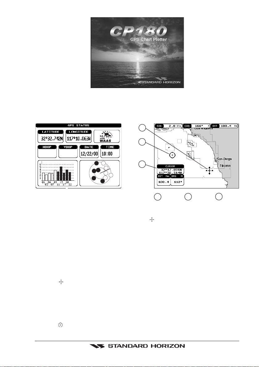
Figure 3.1.0 - Example of Start-Up page on CP180
3. When the GPS Chart Plotter is first turned on it will take some time for the GPS to acquire
a fix of your position. Look closely at the GPS Status page and you will see satellites and
relative signal strengths. After a fix is received the GPS Chart Plotter will automatically
switch to the Chart page with the ships icon centered on the screen.
1
2
1.2
1.5
AM
22
01
03
20
17
06
09
07
13
11
Figure 3.1.0a - GPS Status and Chart pages
3
Cursor
1
Ships
2
Icon
3
Cursor
window
4. On the Chart page the ShuttlePoint knob is used to pan around the chart. Move the ShuttlePoint
knob to the left and you will notice a cross hair
appears, this is called the cursor.
5. When you move the ShuttlePoint knob you will notice DST and BRG values in the Data
window change. This shows the Distance and Bearing from the GPS Fix of your vessel
to the position of the Cursor.
6. If the cursor is moved to the edge of the screen the GPS Chart Plotter will automatically
pan in the desired direction.
3.1.1 Cursor Vs. Home Mode
Cursor Mode
When the
In Cursor mode the position of the vessel will not stay in the center of the page and will move
right off the edge of the screen (as your boat moves) Cursor mode allows you to pan around
and look at areas on the map. In this mode your can also measure distance and bearings
from your current position.
Home mode
When the
cursor is shown on the Chart page, this is called Cursor mode.
ships icon is shown on the Chart page (cursor is not shown) you are in Home
GPS Chart Plotters Page 29
Page 28
mode. Now as the ship moves through the water the vessels position will be kept in the
center of the display.
NOTE
To change from Cursor mode to Home mode press [CLR].
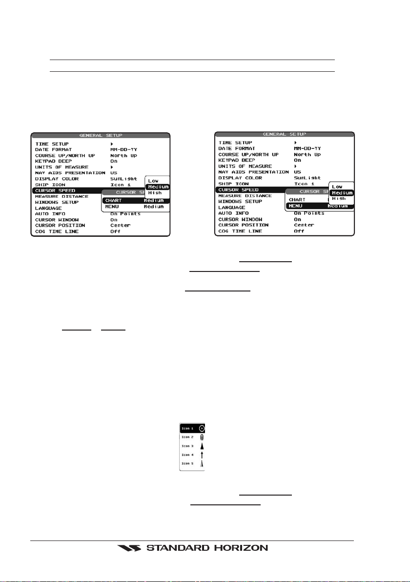
3.1.2 Cursor and Menu selection speed
The GPS Chart Plotter allows you to control the speed the Cursor moves when the
ShuttlePoint knob is pressed. To change the speed:
Figure 3.1.2 - Cursor Speed menu
1. Press [MENU]. Move the ShuttlePoint knob to highlight SETUP MENU and press [ENT].
2. Move the ShuttlePoint knob to highlight
the ShuttlePoint knob to the right.
3. Move the ShuttlePoint knob to highlight
ShuttlePoint knob to the right.
4. The menu now shows two selections, CHART and MENU which allows the Cursor
Speed to be selected to High, Medium or Low on Chart page or within the menus.
5. With
CHART or MENU selected, press [ENT] or move the ShuttlePoint knob to the right.
Move the ShuttlePoint knob to the desired setting and press [ENT] or move the
ShuttlePoint knob to the right.
6. Press [CLR] until the menu disappears or an easier method is to press the ShuttlePoint
knob to the left a few times.
7. Move the cursor on the Chart page and see if the speed is to your liking.
GENERAL SETUP and press [ENT] or move
CURSOR SPEED and press [ENT] or move the
3.1.3 Changing the Ships Icon
The cursor may be changed to any of the following:
Figure 3.1.3 - Ship icons
1. Press [MENU]. Move the ShuttlePoint knob to highlight SETUP MENU and press [ENT].
2. Move the ShuttlePoint knob to highlight
the ShuttlePoint knob to the right.
Page 30 GPS Chart Plotters
GENERAL SETUP and press [ENT] or move
Page 29
3. Move the ShuttlePoint knob to highlight SHIP ICON and press [ENT] or move the
ShuttlePoint knob to the right to show the popup window with ship icons.
4. Move the ShuttlePoint knob to select the desired icon and press [ENT] or move the
ShuttlePoint knob to the right to select a new icon.
5. Press [CLR] or move the ShuttlePoint knob to the left to exit the menu and show the
Chart page.
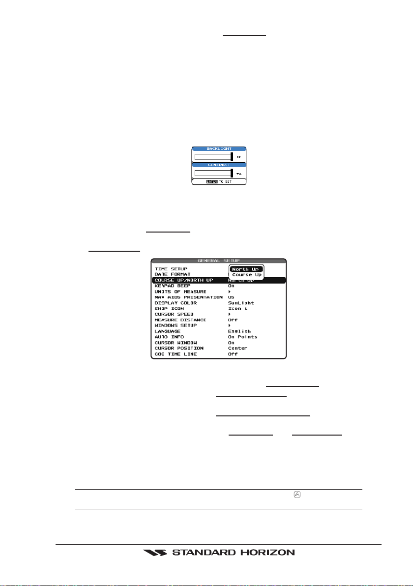
3.1.4 Changing the backlight and contrast
With the GPS Chart Plotter is turned On, briefly press [PWR] to show the light and contrast
popup window. Move the ShuttlePoint knob to the left or right to adjust the LCD backlight
intensity or up or down to change the LCD contrast. Press [ENT] to set.
Figure 3.1.4 - Backlight and Contrast adjustment
3.1.5 Selecting North Up or Course Up
The default selection is NORTH UP, however you may want the top of the Chart page oriented so it will always show the area ahead of the direction your vessel is travelling which is called
COURSE UP.
Figure 3.1.5 - Course Up/North Up menu
1. Press [MENU]. Move the ShuttlePoint knob to highlight SETUP MENU and press [ENT].
2. Move the ShuttlePoint knob to highlight
GENERAL SETUP and press [ENT] or move
the ShuttlePoint knob to the right.
3. Move the ShuttlePoint knob to highlight
COURSE UP/NORTH UP and press [ENT] or
move the ShuttlePoint knob to the right.
4. Another popup window will be shown with
NORTH UP and COURSE UP, move the
ShuttlePoint knob to the desired selection and press [ENT] or move the ShuttlePoint
knob to the right.
5. Press [CLR] or move the ShuttlePoint knob to the left to exit the menu and show the
Chart page.
NOTE
When the GPS Chart Plotter is in COURSE UP mode a small arrow icon will be shown on the
Chart page indicating the direction of North.
GPS Chart Plotters Page 31
Page 30
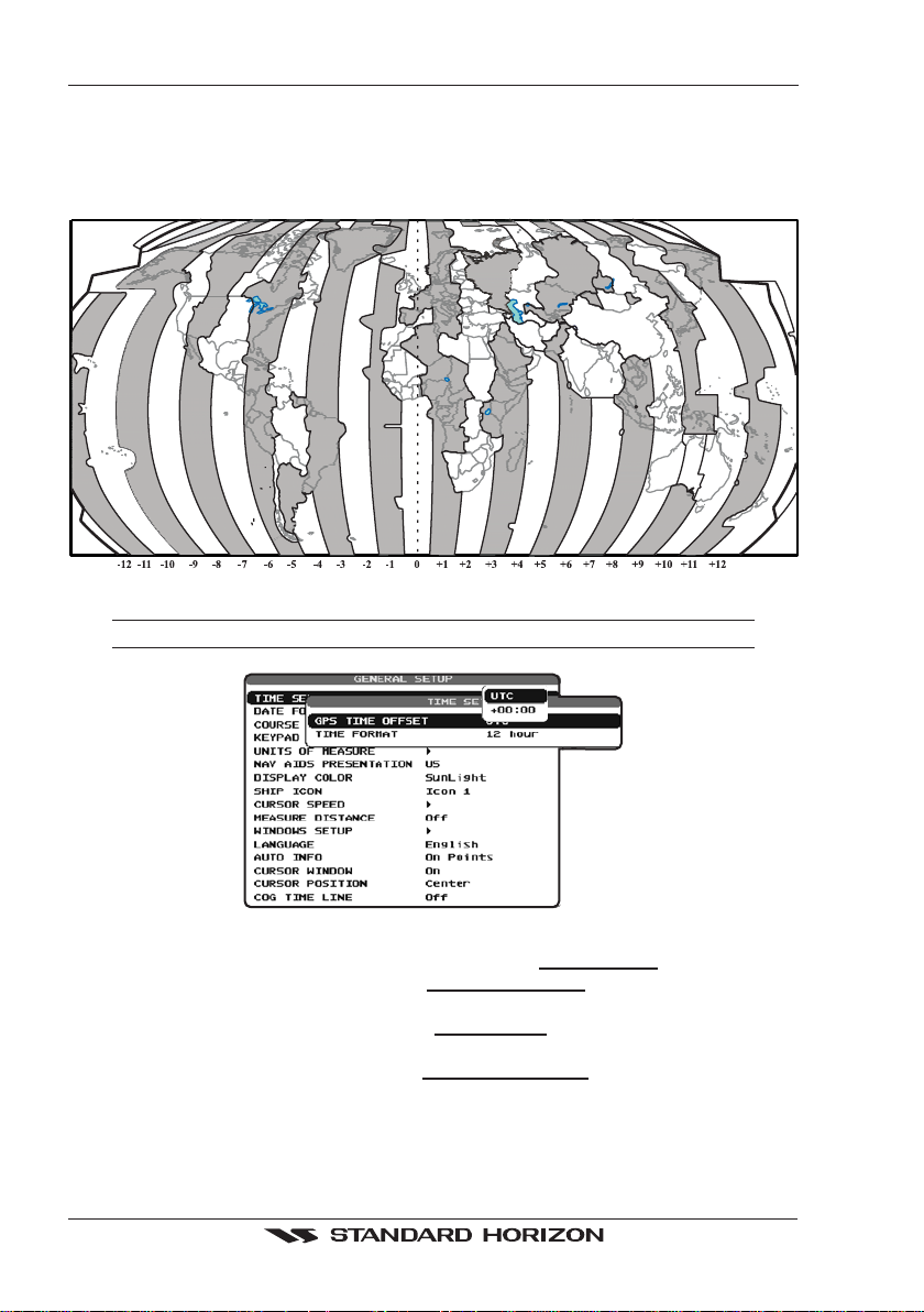
3.2 ADJUSTING THE TIME
The time information supplied by the GPS satellites is in Universal Time Coordinates (UTC or
Greenwich England Mean Time). To change the GPS Chart Plotter to read the correct time, first
you must figure out the offset and if it is daylight savings time. For example on the West coast of
the United States or Pacific Standard Time the offset needed would be –08:00 or –07:00 for daylight
savings time, Eastern Standard Time –05:00 or –04:00 for daylight savings time.
Figure 3.2 - Adjusting Time
NOTE
This map shows offset for standard time. For daylight saving time, subtract one hour from the offset time.
Figure 3.2a - Time Setup menu
1. Press [MENU]. Move the ShuttlePoint knob to highlight SETUP MENU and press [ENT].
2. Move the ShuttlePoint knob to highlight
GENERAL SETUP and press [ENT] or move
the ShuttlePoint knob to the right.
3. Move the ShuttlePoint knob to highlight
TIME SETUP and press [ENT] or move the
ShuttlePoint knob to the right.
4. Move the ShuttlePoint knob to highlight
GPS TIME OFFSET and press [ENT] or move
the ShuttlePoint knob to the right.
5. Move the ShuttlePoint knob down to select +00:00, press [ENT] and move the
ShuttlePoint knob to the right to edit the number.
6. Look at the table and find the offset for your area. You will need to enter this offset to
Page 32 GPS Chart Plotters
Page 31

make the GPS Chart Plotter shows the correct time.
7. Move the ShuttlePoint knob to the “+”. Move the ShuttlePoint knob up or down to change
to the desired offset.
8. Next move the ShuttlePoint knob to the right to select Hours and move the ShuttlePoint
knob up or down to change the hour.
9. Repeat this method to change the minutes, if necessary.
10. Once you have the correct GPS time offset, press [ENT] to set.
3.3 SELECTING LORAN TD OR OTHER COORDINATE SYSTEM
The GPS Fix coordinates can be changed to show Latitude/Longitude, Loran TD’s or UTM.
Below is the window that will appear when customizing the Coordinate System.
Figure 3.3 - Coordinate System menu
1. Press [MENU]. Move the ShuttlePoint knob to highlight SETUP MENU and press [ENT].
2. Move the ShuttlePoint knob to highlight
the ShuttlePoint knob to the right.
3. Move the ShuttlePoint knob to highlight
ShuttlePoint knob to the right.
4. Move the ShuttlePoint knob to highlight
move the ShuttlePoint knob to the right.
5. Move the ShuttlePoint knob to highlight the desired coordinate type and press [ENT] or
move the ShuttlePoint knob to the right.
6. Press [CLR] or move the ShuttlePoint knob to the left until the Chart page is shown.
If the TD is selected, you should set the Chain, Pair, ASF1, ASF2 and Alter. If the TD numbers are
not correct the Pair letters may be backwards. Reversing the two letters usually solves this issue.
Example Y/Z change to Z/Y.
ADVANCED SETUP and press [ENT] or move
NAVIGATE and press [ENT] or move the
COORDINATE SYSTEM and press [ENT] or
NOTE
3.4 CHANGING THE CHART COLOR
The GPS Chart Plotter has preprogrammed settings allowing you to customize the look of
the Chart page. The default is “Sunlight” however there are other settings; Normal, Classic
and Night. Night is very useful during evening hours so not to impair night vision.
GPS Chart Plotters Page 33
Page 32

Figure 3.4 - Display Color menu
1. Press [MENU]. Move the ShuttlePoint knob to highlight SETUP MENU and press [ENT].
2. Move the ShuttlePoint knob to highlight
GENERAL SETUP and press [ENT] or move
the ShuttlePoint knob to the right.
3. Move the ShuttlePoint knob to highlight
DISPLAY COLOR and press [ENT] or move the
ShuttlePoint knob to the right.
4. A popup window will be shown with Normal, Classic, NOAA, Night and Sunlight. Move
the ShuttlePoint knob to the desired selection and press [ENT] or move the ShuttlePoint
knob to the right.
5. Press [CLR] or move the ShuttlePoint knob to the left to exit the menu and show the
Chart page.
3.5 SELECTING PAGES USING SOFT KEYS ON CP300/CP300i
The Soft Keys located under the LCD on the CP300 and CP300i are used to select the pages
quickly without the need to go into the menu. The default pages are VIDEO, CHART, NAV,
HIGHWAY, CELESTIAL and NMEA DISPLAY.
When one of the Soft Keys is pressed popup windows above each Soft Key are shown with
the key description. Press the Soft Key with the desired page description and the GPS Chart
Plotter will change to that page.
Figure 3.5 - Screen display pages
3.6 CUSTOMIZING THE SOFT KEYS ON CP300/CP300i
The Soft Keys (CP300 and CP300i) can be individually customized from the default pages
(discussed above) to the following: CHART, CHART/COMPASS, CHART/HIGHWAY,
NAVIGATION, HIGHWAY, CELESTIAL, GPS STATUS, DSC LOG, DSC DIRECTORY,
Page 34 GPS Chart Plotters
Page 33

NMEA DISPLAY, NMEA DATA, DEPTH TREND, WIND SPEED TREND, TEMP TREND,
SOG TREND, MARKS/WAYPOINTS, USER C-CARD and VIDEO INPUT.
When the Optional FF520 50/200kHz BLACK BOX FISH FINDER is connected, any Soft
Key can be customized to show 50 or 200kHz full page, 50 or 200kHz Chart/Fish split screen
and zoom screens.
Figure 3.6 - Window options of the selected Soft Key on CP300/CP300i
1. To change, momentarily press any of the Soft Keys, then press and hold the Soft Key
you want to customize.
2. A popup window will be shown with the above settings.
3. Move the ShuttlePoint knob up or down to select the desired page.
4. Press [ENT] or move the ShuttlePoint knob to the right to save the page to the selected
Soft Key.
3.7 OTHER SETTINGS IN GENERAL SETUP MENU
You will notice the GENERAL SETUP menu has other selections that allow you to customize:
TIME SETUP Selects a sub-menu to allow the time setup. It is possible to set the GPS Time Offset,
DATE FORMAT Allows choosing date format MM-DD-YY or DD-MM-YY.
COURSE UP/NORTH UP Selections are:
KEYPAD BEEP Allows the beep produced when a key is pressed to be turned on or off. UNITS OF MEASURE Units of Measure can be selected for Distance, Speed, Depth, Altitude and Temperature. NAV AIDS PRESENTATION Allows the Nav Aids presentation to be drawn using NOAA symbology when US is
DISPLAY COLOR Changes the background colors of the chart page to enhance the visibility of the screen
SHIP ICON Allows selection of one of 5 choices of ship icons that represent your vessels position
choosing the UTC or Local Time display, and the Time Format, switching 12 or 24 hours
time format.
North Up : The Top of the page is fixed to North
Course Up: The top of the page is orientated to the direction the vessel is heading.
selected or International symbols will be used when International is selected. When
selected these functions affect how the icons for Lights, Signals, Buoys and beacons are
displayed.
depending on the surrounding light conditions. Normal is recommended when the GPS
Chart Plotter is not exposed to the direct sunlight. When this mode is set the maps are
displayed in order to use colors as similar as possible to ones used in the original paper
charts. Classic uses vivid chart colors presentation. NOAA allows setting NOAA paper
chart colors presentation. Night is recommended when the environment is dark in order
to reduce the glare of the display. The GPS Chart Plotter displays maps and screen in
darker colors. Sunlight (default) is designed to enhance the visibility of the screen when
the GPS Chart Plotter is exposed to sunlight. The maps are much brighter than in the other
modes and the depth areas are filled with the white color so different depth areas are not
easily distinguishable.
shown on the chart page.
GPS Chart Plotters Page 35
Page 34

CURSOR SPEED Selects the preferred speed among Low, Medium and High for the cursor in the Chart page
MEASURE DISTANCE When this function is turned on allows a distance to be measured between two points
WINDOWS SETUP This menu selection allows the data windows to be customized on the Chart and
LANGUAGE Allows changing the language for menus and data screens. AUTO INFO By default when the cursor is moved over a buoy, Mark or other item a popup window will
CURSOR WINDOW By default when the cursor is moved a window is shown with the lat/lon Distance and
CURSOR POSITION The position of the cursor (vessels location) can be customized so it centered in the middle
COG TIME LINE Is a line projected from the vessel icon which indicates the distance your vessel will travel
and within the menu.
using the ShuttlePoint knob and [ENT].
Navigation pages.
show information of the item. This menu item allows the window to be turned on or off.
bearing from the vessels location to the cursor. This selection allows the window to be
turned off.
or centered on the bottom of the chart page. The default is “Center”.
at the current speed. Selections are 2, 10, 30 minutes, 1, 2 hours and infinite.
3.8 INFORMATION PAGE
From Main Menu page it is possible to select an Information page containing Software,
Chart and Optional devices information.
Figure 3.8 - Example of Information page on CP180
1. Press [MENU]. Move the ShuttlePoint knob to highlight SETUP MENU and press [ENT].
2. Move the ShuttlePoint knob to highlight
About... and press [ENT] or move the
ShuttlePoint knob to the right.
3. The Information page appears on the screen (see the previous Figure).
4. Press [CLR] or move the ShuttlePoint knob to the left to exit and show the Chart page.
Page 36 GPS Chart Plotters
Page 35

4. USING FIND SERVICES & MORE FUNCTION
With a C-MAP NT+/MAX C-CARD installed the GPS Chart Plotter allows you to search for
a Port Service, Port, Tide Stations, Wrecks, Obstructions, POIs, Lakes, User Points, or
GPS Coordinates.
4.0 PORT SERVICES
With a C-MAP NT+/MAX C-CARD installed, the GPS Chart Plotter can find Port Services
contained on the map.
1. Press [MENU]. Move the ShuttlePoint knob to highlight
[ENT].
2. Move the ShuttlePoint knob to highlight
PORT SERVICES and press [ENT] or move the
ShuttlePoint knob to the right.
3. A popup window will be shown with the Port Services.
4. Move the ShuttlePoint knob to highlight the desired Service and press [ENT].
5. Another popup window will show the name, distance and position of the Services closest
to your location.
6. Using the ShuttlePoint knob, highlight the desired Service and press [ENT] which will
show the name and phone number of the Service.
7. Press [CLR] which will show the available Services at the location.
8. Press [CLR] to show the actual position of the Services.
FIND SERVICES and press
Figure 4.0 - Port Services
4.1 OTHER AVAILABLE SEARCHES
PORT : Shows the list of all ports stored on the C-CARD in distance order. Pressing [MENU] shows
TIDE STATIONS : Searches for the closest Tide Station and shows the information of the selected tide station. WRECKS : Searches for the closest Wreck. OBSTRUCTIONS : Searches for the closest Obstruction. LAKES INFORMATION : Searches and shows information on the selected Lake. LAKES BY NAME : Shows the list of all lakes stored on the C-CARD in alphabetic order. Pressing [MENU] to
POINTS OF INTEREST : Searches and shows information on the selected Point Of Interest. USER POINTS : Searches and shows on the Chart page the closest User Points (Marks or Waypoints). COORDINATES : Searches and shows on the Chart page GPS Coordinates.
GPS Chart Plotters Page 37
the list of all ports in alphabetic order; press [MENU] again to insert the name to search.
insert the Lake name.
Page 36

4.2 INFO ON LAKES
4.2.0 Quick Info On Lakes
Upon viewing the chart of a lake, you will click on to query the available information
immediately displayed with many details. For example, see the following picture:
Figure 4.2.0 - Example of Lakes info
When the cursor is placed over the icon, the icons of the available services are shown:
Figure 4.2.0a - Quick Info: available services
If you press [ENT] all available information about the cartographic point under the cursor
will be shown. See the next paragraph.
4.2.1 Full Info On Lakes
The following is an example of Full Info on Lakes:
Figure 4.2.1 - Example of Full Info page
Page 38 GPS Chart Plotters
Page 37

To see the "Fishing" object press [MENU] (when the "Fishing" object is highlighted). On the
screen appears:
Figure 4.2.1a - Example of picture associated to the Fishing object
GPS Chart Plotters Page 39
Page 38

Page 40 GPS Chart Plotters
Page 39

5. C-MAP MAX OVERVIEW
5.0 INSERTING THE C-CARD
Hold the C-CARD by the long inclined side so that you can see the C-MAP label.
Figure 5.0 - Inserting C-CARD
Open the door, gently push the C-CARD into the slot: push the C-CARD in as far as it will
go, then close the door.
Figure 5.0a - Inserting C-CARD (Details)
C-MAP MAX is a major evolution of the NT/NT+ product technology. Key points are:
New Data Features
· Tides and Currents (intuitive arrows show direction and strength)
· World Background Charts with terrestrial data
· Value Added Data (Pictures and Diagrams, Land Data)
· Enhanced Port Info
New Presentation Features
· Clear Info (sophisticated "Human Dictionary" to translate Nav-Aid abbreviations found
on paper charts)
· Dynamic Nav-Aids (an innovative and dynamic presentation mode)
· Flexi-Zoom (increased Under and Over Zoom between chart levels, resulting in optimal
scale display for any situation)
GPS Chart Plotters Page 41
Page 40

· Dynamic Elevation Data (optimized palettes for GPS Chart Plotters; includes new
NOAA palette)
· Perspective View ("Real World" perspective view of the chart, updated real-time during
navigation)
+
MAX and NT/NT
· When NT
data from both charts (depending on the current position).
· When NT
C-CARD coexistence
+
data and MAX data cover different areas, the GPS Chart Plotter receives
+
data and MAX data cover the same area, the GPS Chart Plotter receives
data only from MAX chart.
Page 42 GPS Chart Plotters
Page 41

6. MAP FUNCTIONS
6.0 MAX FUNCTIONS MENU
1. Press [MENU]. Move the ShuttlePoint knob to highlight SETUP MENU and press [ENT].
2. Move the ShuttlePoint knob to highlight
the ShuttlePoint knob to the right. The MAX Functions menu appears on the screen:
Figure 6.0 - Map Functions Menu on CP180/CP180i
The available Functions are described in the following.
6.0.0 Zoom Type
Allows zooming into our out on the chart page. Zoom Mode has two options; STANDARD
(default) or FLEXI-ZOOM. When in FLEXI-ZOOM mode, a short [ZOOM...] push causes
a change of chart, while a long [ZOOM...] push (press and hold) causes a pop-up window
to be displayed on a corner of the screen. The window shows the current Zoom Factor. By
pressing [ZOOM IN]/[ZOOM OUT] the map is expanded or compressed according to the
zoom factor selected. The window is automatically closed if [ZOOM...] is not pressed for 2
seconds and the selected zoom factor will be used at the next zoom in/out.
To activate this function follow the procedure:
1. Press [MENU]. Move the ShuttlePoint knob to highlight
2. Move the ShuttlePoint knob to highlight
the ShuttlePoint knob to the right.
3. Move the ShuttlePoint knob to highlight
ShuttlePoint knob to the right.
4. The menu now shows two selections,
5. Move the ShuttlePoint knob to select the selection and press [ENT].
6. Press [CLR] until the menu disappears or an easier method is to move the ShuttlePoint
knob to the left a few times.
MAX FUNCTIONS and press [ENT] or move
SETUP MENU and press [ENT].
MAX FUNCTIONS and press [ENT] or move
ZOOM TYPE and press [ENT] or move the
STANDARD or FLEXI-ZOOM.
6.0.1 Fonts & Symbols ON THE CP300/CP300i
On MAX charts it is possible to set the size of all names and symbols drawn on the charts,
selecting between Normal size (the regular characters size) and Large size.
To activate this function follow the procedure:
1. Press [MENU]. Move the ShuttlePoint knob to highlight
2. Move the ShuttlePoint knob to highlight
the ShuttlePoint knob to the right.
3. Move the ShuttlePoint knob to highlight
the ShuttlePoint knob to the right.
4. The menu now shows two selections,
GPS Chart Plotters Page 43
MAX FUNCTIONS and press [ENT] or move
FONTS & SYMBOLS and press [ENT] or move
NORMAL or LARGE.
SETUP MENU and press [ENT].
Page 42

5. Move the ShuttlePoint knob to select the selection and press [ENT].
6. Press [CLR] until the menu disappears or an easier method is to move the ShuttlePoint
knob to the left a few times.
NORMAL size LARGE size
Figure 6.0.1 - Example of Normal size (on the left side) and Large side (on the right side) settings
6.0.2 Perspective View
Chart data may be projected in perspective mode during navigation. This function allows
setting the panoramic View of the chart. As the upper side of the map is more compressed
than the lower side, a wider map area is visible. The perspective view allows showing more
chart information immediately ahead and around the cursor.
Figure 6.0.2 - Perspective View
To activate this function follow the procedure:
1. Press [MENU]. Move the ShuttlePoint knob to highlight
2. Move the ShuttlePoint knob to highlight
MAX FUNCTIONS and press [ENT] or move
SETUP MENU and press [ENT].
the ShuttlePoint knob to the right.
3. Move the ShuttlePoint knob to highlight
PERSPECTIVE VIEW and press [ENT] or
move the ShuttlePoint knob to the right.
4. The menu now shows two selections,
ON or OFF.
5. Move the ShuttlePoint knob to select the selection and press [ENT].
6. Press [CLR] until the menu disappears or an easier method is to move the ShuttlePoint
knob to the left until the chart page is shown.
6.0.3 Dynamic Nav-Aids
This function allows the Nav-Aids to be turned On or Off. The blink period and color of each
Nav-aid is read from the Nav-Aid attributes available on the data cartridge. When the ship
is inside the Nav-Aid nominal range, the light of the Nav-Aid will start blinking.
Page 44 GPS Chart Plotters
Page 43

When Dynamic Nav-Aids option is set to On, when the flashing light is Off, or when fix
position is out of the sector, the light color is displayed by using a faint light color.
To activate this function follow the procedure below:
1. Press [MENU]. Move the ShuttlePoint knob to highlight
2. Move the ShuttlePoint knob to highlight
MAX FUNCTIONS and press [ENT] or move
SETUP MENU and press [ENT].
the ShuttlePoint knob to the right.
3. Move the ShuttlePoint knob to highlight
DYNAMIC NAV-AIDS and press [ENT] or move
the ShuttlePoint knob to the right.
4. The menu now shows two selections,
ON or OFF.
5. Move the ShuttlePoint knob to select the selection and press [ENT].
6. Press [CLR] until the menu disappears or an easier method is to move the ShuttlePoint
knob to the left until the chart page is shown.
6.0.4 Safety Status Bar (DSI - Data Safety Indicator)
When Safety Status Bar is On, a status bar with six boxes showing the status of certain
functions is displayed. Any warning or alarm condition is identified by the red color to
indicate possible risk.
To activate this function follow the procedure:
1. Press [MENU]. Move the ShuttlePoint knob to highlight
2. Move the ShuttlePoint knob to highlight
MAX FUNCTIONS and press [ENT] or move
the ShuttlePoint knob to the right.
3. Move the ShuttlePoint knob to highlight
SAFETY STATUS BAR and press [ENT] or
move the ShuttlePoint knob to the right.
4. The menu now shows the following selections:
OFF (The Safety Status Bar is not shown), ICON (The Safety Status Bar is not shown,
but a Warning alarm Icon is shown on the corner of the map screen as soon as any item
controlled by the DSI function returns an alarm condition. The Warning Icon remains
displayed until the alarm condition persists. Placing the cursor over this Icon, a quick
help message is shown next to the Icon, allowing the Safety Status Bar to be shown.
In this case - when the Safety Status Bar is opened via Warning alarm Icon - it is allowed
to obtain information about each “active” Safety Status box (the red ones): it is possible
to select them by ShuttlePoint knob movement left/right, and a list of active alarms is
shown underneath the selected box. By pressing [CLR], the Safety Status Bar is
removed from the screen.
5. Move the ShuttlePoint knob to select the selection and press [ENT].
6. Press [CLR] until the menu disappears or an easier method is to press the ShuttlePoint
knob to the left a few times.
SETUP MENU and press [ENT].
ON (The Safety Status Bar is shown),
Figure 6.0.4 - Safety Status Bar
Boxes definition is as follows:
Zoom
♦ Normal: when the chart is displayed at normal scale.
♦ U. Zoom: red when the chart is under-zoomed out more than twice normal
scale, gray otherwise.
GPS Chart Plotters Page 45
Page 44

♦ O. Zoom: red when the chart is over-zoomed in more than twice normal scale,
gray otherwise.
♦ Chart Lock: red when the chart is zoomed in more than twice normal scale,
gray otherwise.
NOTE
U. Zoom, O. Zoom and chart lock are used with Flexi zoom selected.
Best Map
Red when a more detailed chart is available under the cursor position.
Data Off
Red when at least one of the following objects or layers is turned off (by the user):
Depths/soundings; Wrecks/obstructions; Tracks/routes; Attention Areas; Nav-Aids.
Declutter
Displays red when clearing overlapping objects.
Dangers
Red when “Guardian Technology” detects one of the following objects: Land, Intertidal, Depth Area, Rocks, Obstructions, Shoreline Constructions, Fishing Facility,
Wrecks, Dragged area, Diffusion area, Mooring facilities, Pingos and Production installations.
Caution
Red when “Guardian Technology” detects cautionary or restricted area.
6.0.5 Currents Prediction
It is possible to see the variation of the Tidal arrows on the selected area at any given time.
To activate this function follow the procedure:
1. Press [MENU]. Move the ShuttlePoint knob to highlight
2. Move the ShuttlePoint knob to highlight
MAX FUNCTIONS and press [ENT] or move
SETUP MENU and press [ENT].
the ShuttlePoint knob to the right.
3. Move the ShuttlePoint knob to highlight
CURRENTS PREDICTION and press [ENT] or
move the ShuttlePoint knob to the right.
4. A window is shown on the low-left side of the chart. On the CP300/CP300i, press [S
to set the date and time manually, and [I
press [E
XIT] to exit. On the CP180/CP180i press [ENT] to set the date and time manually,
NCR. TIME]/[DECR. TIME] to decrease/increase time;
ET TIME]
and [GOTO]/[MENU] to decrease/increase time; press [CLR] to exit.
6.0.6 Pictures & Diagrams
Using C-Map MAX data cards allows you to show pictures or diagrams on the Chart Plotter
display. These Pictures are typically used to facilitate the identification of cartographic
objects or places around the map: they can be the landscape layout nearby a harbour, the
shape of a bridge or of a buoy etc.
On some objects, such as bridges, the image associated can represent the Diagram
representing the shape of the objects and the various characteristics (length, height, type
of bridge etc.).
Page 46 GPS Chart Plotters
Page 45

Figure 6.0.6 - Pictures and Diagrams
The pictures or diagrams can be a MULTIMEDIA OBJECT or they can be associated to a
generic cartographic object, like a port marina.
How to show the pictures or diagrams of a Multimedia Object
They are shown on the chart page with the camera icon
Move the cursor over the camera icon. You will get the quick info on the object and there
will be the camera icon on the top bar of the window:
Figure 6.0.6a - Example of Quick Info on MULTIMEDIA object
Press [IMAGE] on the CP300/CP300i or press [ENT] on the CP180/CP180i for 1 second to
display the image on the screen; press [E
XPAND] on the CP300/CP300i or [ENT] on the
CP180/CP180i to open the Full info on the object:
Figure 6.0.6b - Example of Full Info on MULTIMEDIA object
On the Full Info, there will be the small camera icon on a corner of the square containing
the object icon.
To see the picture press [MENU] when the object with a picture is highlighted.
When the picture is shown, it is possible to fit it to screen by pressing [ENT].
When the picture is shown, it is possible to change the contrast by pressing [ZOOM IN] or
[ZOOM OUT].
When the picture is shown, it is possible to display the next picture associated, if any, by
pressing the ShuttlePoint knob left or right.
GPS Chart Plotters Page 47
Page 46

6.0.7 Enhanced Port Info
MAX charts include additional port services that were not present before. Additional
attributes of Port Areas and Port Marinas have been included (Location, Country, Region,
State, Harbour master telephone number etc.).
Page 48 GPS Chart Plotters
Page 47

7. CREATING MARKS
Definitions:
MARK
Can be a stand alone position or be linked to a Route. A Mark is place on the Chart page using
[MARK] or by entering in information in the
WAYPOINTS
Always linked to a Route. Are placed on the Chart page using [ROUTE].
The difference between a Mark and a Waypoint is
a. When a Route is created using WAYPOINTS and the ROUTE is deleted the WAYPOINTs are
also deleted.
b. If a Route is created using MARKS and the ROUTE is deleted the MARKs remain.
7.0 CREATING A NEW MARK USING THE CHART PAGE
1. Move the ShuttlePoint knob to the desired or approx. Lat/Lon and press [MARK].
2. You will notice a Mark is placed under the location of the Cursor and a popup window
is shown with the exact Lat/Lon of the Mark.
3. If the position is incorrect on the CP180/CP180i press [ENT], select
ShuttlePoint knob and press [ENT]. On the CP300/CP300i, press [E
you to change the position, Mark name, icon type and color of the icon.
Mark placed under Cursor
1
MARK/WAYPONTS List NEW MARK selection.
NOTE
EDIT using the
DIT] that will allow
Lat/Lon of Mark, DST/BRG
2
from vessel location
ONLY for CP180/180i
Press [ENT] to delete, to move,
3
to edit a Mark or to show the
Marks/Waypoint List (Directory)
ONLY for CP300/300i
Press Soft Key to show
4
Marks/Waypoint List
to move or to delete Mark
Vessel location
5
After entering in all the Marks it is a good practice to back up the points to a C-MAP User C-CARD.
Refer to Section 11.
the
,toedit,
5
1
4
Figure 7.0 - Mark creation
NOTE
2
3
7.1 EDITING A MARK
If a Mark has previously been created and you wish to Edit it, move Cursor over the top of
the Mark.
GPS Chart Plotters Page 49
Page 48

Figure 7.1 - Mark editing
1. After a Mark is created on the CP180/CP180i press [ENT], select EDIT using the
ShuttlePoint knob and press [ENT]. On the CP300/CP300i press [E
DIT] to show the edit
popup window.
2. Use the ShuttlePoint knob to change to the Mark Icon, when finished press [ENT].
3. Move the ShuttlePoint knob to the right to select the Mark Name. Press [ENT] and the
first digit in the name will be highlighted.
4. Move the ShuttlePoint knob up or down to select the first character.
5. Move the ShuttlePoint knob to the right to select the next character.
6. Repeat steps 4 and 5 until the Mark name is shown. Press [ENT].
7. Move the ShuttlePoint knob to the right and press [ENT] to change the Mark Icon’s
Color.
8. Move the ShuttlePoint knob to up/down, left/right to select the Mark Icon’s Color. When
finished press [ENT].
9. Move the ShuttlePoint knob to the right to select the Lat/Lon and press [ENT].
10. Move the ShuttlePoint knob up or down to select the first character.
11. Move the ShuttlePoint knob to the right to select the next character.
12. Repeat steps 10 and 11 until the desired position is shown. Press [ENT] and [CLR] to
store the Mark.
7.1.0 Deleting a Mark or Waypoint
Move the cursor over the Mark or Waypoint to delete. On the CP180/CP180i press [ENT],
select
DELETE using the ShuttlePoint knob and press [ENT]. On the CP300/CP300i, press
ELETE]. A Warning popup window will be shown. Select YES and press [ENT].
[D
7.1.1 Moving a Mark or Waypoint
Place the cursor over the Mark or Waypoint which you want to move. On the CP180/CP180i
press [ENT], select
CP300i, press [M
connecting the previous Waypoint position to the new position, is shown:
MOVE using the ShuttlePoint knob and press [ENT]. On the CP300/
OVE]. Use the ShuttlePoint knob to move the cursor. A dotted line,
Figure 7.1.1 - Moving Mark or Waypoint (I)
Press [ENT] ([CLR] to abort the move), the Waypoint appears in the new position.
Page 50 GPS Chart Plotters
Page 49

Figure 7.1.1a - Moving Mark or Waypoint (II)
7.2 MARKS/WAYPOINTS LIST
The MARKS/WPTS List shows all the Marks and Waypoints that have been stored into the
GPS Chart Plotter. This page also allows you to:
ICON Allows sorting by icon type FIND Searches through the Marks or Waypoints to find a point by name using the ShuttlePoint knob LOCATE Shows the position of a Mark or Waypoint on the Chart page EDIT Allows you to edit a previous stored Mark or Waypoint NEW MARK Allows entering in Marks, editing icon type and position MODE This selection controls how the Marks or Waypoints are shown on the Chart page. Selections are:
DELETE Opens a window with two options: "DELETE SELECTED" for deleting the selected point and
SORT Sorts the name of the Mark or Waypoint in ascending or descending order
SEND Sends the stored points to a external device (PC) capable of listening to NMEA WPL and RTE
RECEIVE When selected, receives points from an external device (PC) that is capable of sending NMEA
The SEND and RECEIVE functions are usually used by navigation programs running on a Personal
Computer.
a. SHOW - icon and name are shown
b. ICON - only icon (no name) is shown
c. HIDE - Mark or Waypoint is hidden
d. SHOW ALL - All Marks or Waypoints are shown
e. ICON ALL - All Icons are shown without name
f. HIDE ALL - All Marks or Waypoints are hidden
"DELETE ALL" for deleting all stored points.
sentences.
WPL sentence.
NOTE
Figure 7.2 -Example of Marks/Waypoints List
GPS Chart Plotters Page 51
Page 50

7.3 CREATING A NEW MARK WITH THE USER POINTS LIST
NOTE
This function is very useful if you have a list of Marks that you want to enter into the GPS Chart
Plotter.
1. Press [MENU]. Move the ShuttlePoint knob to highlight USER POINTS and press [ENT].
2. Move the ShuttlePoint knob to highlight
3. The MARKS/WAYPOINTS List page will be shown (see previous Figure).
4. To create a New Mark, move the ShuttlePoint knob to the right to highlight
and press [ENT].
5. Press [ENT] to change to show the Icon popup window.
6. Move the ShuttlePoint knob to highlight the desired Icon and press [ENT].
7. Move the ShuttlePoint knob to the right to select the Mark name. Press [ENT] and the
first digit in the name will be highlighted.
8. Move the ShuttlePoint knob up or down to select the first character.
9. Move the ShuttlePoint knob to the right to select the next character.
10. Repeat steps 8 and 9 until the Mark name is shown. Press [ENT].
11. Move the ShuttlePoint knob to the right to select the Lat/Lon and press [ENT].
12. Move the ShuttlePoint knob up or down to select the first character.
13. Move the ShuttlePoint knob to the right to select the next character.
14. Repeat steps 12 and 13 until the desired position is shown. Press [ENT] and [CLR], a
WARNING “Save the new Mark?” popup window will be shown, move the ShuttlePoint
knob to the right or left to select
After entering in all the Marks it is a good practice to back up the points to a C-MAP User C-CARD.
Refer to Section 11.
MARKS/WPTS and press [ENT].
NEW MARK
YES or NO and press [ENT].
NOTE
7.4 GOTO CURSOR
The GPS Chart Plotter allows you to quickly start navigating to the Cursor, Mark or Route.
GOTO CURSOR
1. Move the ShuttlePoint knob to the exact position you want to navigate to.
2. Press [GOTO] and a GOTO popup window will be shown
Figure 7.4 - GO TO menu
3. Move the ShuttlePoint knob to highlight CURSOR and press [ENT].
4. The GPS Chart Plotter is now navigating from your current position to the location
selected at step 1.
Page 52 GPS Chart Plotters
Page 51

Figure 7.4a - Navigating to Cursor Example
5. Now the GPS Chart Plotter shows a bearing line between the vessels location and the
destination point. A popup window shows the Distance (DST) and Bearing (BRG) from
the vessels location to the destination point.
6. The GPS Chart Plotter is in Cursor mode, to switch to Home mode press [CLR] so the
vessel will stay in the center of the page.
7. On the CP300/CP300i two Soft Keys are also shown that allow you to quickly switch to
the HIGHWAY page or to stop navigation.
8. To STOP Navigation, press [GOTO] and the WARNING page is shown. Select
STOP
and press [ENT].
7.5 GOTO MARK
1. Move the ShuttlePoint knob to an open position (no buoy, warning etc. under the cursor)
on the Chart page.
2. Press [GOTO] to show the GOTO popup window.
3. Move the ShuttlePoint knob to highlight
WAYPOINTS List.
4. Move the ShuttlePoint to the highlight the desired Mark or Waypoint and press [GOTO].
5. You will notice a circle is drawn around the Icon Symbol. This means the GPS Chart
Plotter is now navigating to the point.
6. Press [CLR] to switch to the Chart page or Highway page to start navigating to the point.
MARK and press [ENT] to show the MARKS/
GPS Chart Plotters Page 53
Page 52

Page 54 GPS Chart Plotters
Page 53

8. MAN OVER BOARD (MOB) FUNCTION
During navigation, the “MOB” feature provides a one-touch method of storing a location,
such as a point were a crew member fell overboard. In this mode, the GPS Chart Plotter
places a MOB point on the Chart page and all the navigation data shown is related to
navigating back to this point, allowing you to retrace your path to the MOB point efficiently.
1. On the Chart page, press [MOB] to start navigating back to the point.
2. You will notice a MOB Mark will be on the Chart page and all navigation is referring back
to this point.
3. On the CP300/CP300i: If the cursor is moved over the MOB Icon, the popup windows
over Soft Keys will be shown allowing quick access to the Navigation or Highway pages.
8.0 DELETING A MOB POINT
1. Move the ShuttlePoint knob until the cursor is over the top of the MOB icon.
2. On the CP180/CP180i press [ENT], select
CP300i press [D
point.
3. Move the ShuttlePoint knob to highlight
ELETE], a popup window will be shown to confirm deleting the MOB
DELETE and press [ENT]. On the CP300/
YES and press [ENT].
GPS Chart Plotters Page 55
Page 54

Page 56 GPS Chart Plotters
Page 55

9. ROUTES
The GPS Chart Plotter has the capability to store, for CP180/CP180i: 20 Routes with a
maximum of 30 Waypoints each, for CP300/CP300i: 50 Routes with a maximum of 30
Waypoints each.
A Route can consist of Waypoints or Marks. The difference is when a Route is made using
Waypoints and the Route is deleted the Waypoints are also deleted. However if a Route is
made of Marks and the Route is deleted the Marks stay in memory.
9.0 CREATING A ROUTE USING WAYPOINTS
1. On the Chart page move the ShuttlePoint knob to the Lat/Lon of the starting Waypoint
in the Route.
2. Press [ROUTE], you will notice the Starting Waypoint
cursor.
3. Move the ShuttlePoint knob to the second Lat/Lon of the next leg
4. Press [ROUTE]. You will notice another Waypoint is shown under the cursor and a line
joins the starting Waypoint to the Second Waypoint.
will be placed under the
in the Route.
Figure 9.0 - Creating a Route using Waypoints
5. Repeat steps 3 and 4 until all Waypoints are entered into the Route.
NOTE
At this point the Route is saved as ROUTE01. If you would like to save the Route under a specific
name follow the remaining steps.
6. To name the Route press [MENU]. Move the ShuttlePoint knob to highlight USER
POINTS and press [ENT].
7. Move the ShuttlePoint knob to highlight
8. Move the ShuttlePoint knob to highlight
ROUTE and press [ENT].
REPORT and press [ENT] or move the
ShuttlePoint knob to the right.
9. Move the ShuttlePoint knob to highlight
NAME and press [ENT]. A popup window will
be shown.
10. Move the ShuttlePoint knob up/down to change the characters and left/right to select
a different character in the Routes Name.
GPS Chart Plotters Page 57
Page 56

Figure 9.0 - Route Report
11. When finished press [ENT] to save.
12. Press [CLR] to show the Chart page.
9.1 MAKING ADDITIONAL ROUTES
To create another Route the GPS Chart Plotter must be told that you want to create a second
Route.
1. Press [MENU]. Move the ShuttlePoint knob to highlight
USER POINTS and press
[ENT].
2. Move the ShuttlePoint knob to highlight
3. Move the ShuttlePoint knob to highlight
ROUTE and press [ENT].
SELECT and press [ENT] or move the
ShuttlePoint knob to the right.
4. Move the ShuttlePoint knob to an open Route number example Route 2.
5. Press [ENT] or move the ShuttlePoint knob to the right.
6. Press [CLR] or move the ShuttlePoint knob to the left until the Chart page is shown.
7. To create the new Route, follow the steps in Creating a Route using Waypoints or Marks
sections.
9.2 CREATING A ROUTE USING MARKS ON THE CHART PAGE
To create a Route containing Marks you first must create the Marks and show them on the
Chart page.
1. Move the ShuttlePoint knob over the top of a Mark that you wish to be the starting point
in the Route and press [ROUTE].
2. Next move the ShuttlePoint knob until the cursor is over the Mark that you want to be
the next leg in the Route.
3. Press [ROUTE]. You will notice a bearing line joins the first and second Mark which
means these Marks are selected into the Route.
4. Repeat steps 3 and 4 until all Marks are entered into the Route.
NOTE
At this point the Route is saved as ROUTE01. If you would like to save the Route under a specific
name follow the remaining steps.
5. To name the Route press [MENU]. Move the ShuttlePoint knob to highlight USER
POINTS and press [ENT].
6. Move the ShuttlePoint knob to highlight
7. Move the ShuttlePoint to highlight
ROUTE and press [ENT].
REPORT and press [ENT] or move the ShuttlePoint
knob to the right.
8. Move the ShuttlePoint knob to highlight
Page 58 GPS Chart Plotters
NAME and press [ENT] or move the Shuttle-
Page 57

Point knob to the right. A popup window will be shown.
9. Move the ShuttlePoint knob up/down to change the characters and left/right to select
a different character in the Routes Name.
10. When finished press [ENT] to save.
11. Press [CLR] to show the Chart page is shown.
9.3 INSERTING A WAYPOINT INTO A ROUTE
Place the cursor on the navigation line between two points and press [ROUTE]. Move the
ShuttlePoint knob to the desired location of the Waypoint and press [ENT].
9.4 GOTO A ROUTE
9.4.0 By select Route
1. Move the ShuttlePoint knob to an open position (no buoy, warning etc. under the cursor)
on the Chart page.
2. Press [GOTO] to show the GOTO popup window.
3. Move the ShuttlePoint knob to highlight
4. The SELECT ROUTE popup window will be shown.
5. Move the ShuttlePoint knob to the highlight the desired Route and press [ENT].
6. On the Chart page a circle with a Flag is shown on the first leg of the Route and a navigation
line is shown, indicating the GPS Chart Plotter is navigating to the first Waypoint in the
Route.
ROUTE and press [ENT].
Figure 9.4.0 - Select a Route
9.4.1 By Cursor key
1. On the Chart page move the ShuttlePoint knob until the cursor reaches the starting point
of the Route.
2. Press [GOTO] to start following the Route.
3. Press [CLR] twice to revert to Home mode.
9.5 OTHER SETTINGS IN ROUTE MENU
You will notice the ROUTE menu has other selections.
SELECT Choose an available Route to create or choose a stored Route to show and follow on the Chart page.
DELETE Deletes the Route when shown in the above SELECT menu.
REVERSE Reverses the Route, when chosen Starting point is at the end of the Route.
COLOR Allows changing the color of the navigation lines between in leg in the Route.
REPORT The Route Report menu is useful to show details of the Waypoints contained within the Route. This menu
SEND Sends the stored points to a external device (PC) capable of listening to NMEA RTE sentence.
RECEIVE Receive the points from an external device (PC) capable of sending NMEA RTE sentence.
GPS Chart Plotters Page 59
also allows you to enter in your average speed and fuel consumption and calculate the approximate fuel
used when following the Route.
Page 58

Page 60 GPS Chart Plotters
Page 59

10. TRACKS
The GPS Chart Plotter has the capability to store 5 individual tracks and record up to 3000
Track Points.
Before using the Track function you will need to setup the Track function that suits your boat.
The Track function tracks your vessels location as it moves through the water. The Track
function can be setup to lay down a Track for a predetermined time or distance interval. If
you have a fast moving boat you may want to setup the GPS Chart Plotter to record a Track
point every 0.5NM or if you have a sail boat you may want to setup to lay down a Track point
once ever 1 minute.
NOTE
Please note the Track point memory is 3000 points. This means for a long journey you may have to
adjust the time or distance to be able to track your journey. It should be noted when the 3000 Track
points are used up, the first Track point layed down will be deleted when a new point is placed on the
chart.
1. Press [MENU]. Move the ShuttlePoint knob to highlight USER POINTS and press
[ENT].
2. Move the ShuttlePoint knob to highlight
3. Move the ShuttlePoint knob to highlight
ShuttlePoint knob to the right.
4. Move the ShuttlePoint knob to highlight
ShuttlePoint knob to the right.
TRACK and press [ENT].
STEP UNIT and press [ENT] or move the
Dist or Time and press [ENT] or move the
Figure 10 - Distance Units and Time Units
5. Move the ShuttlePoint knob to highlight DISTANCE or TIME step interval and press
[ENT] or move the ShuttlePoint knob to the right.
6. Move the ShuttlePoint knob up/down to the desired step value and press [ENT] or move
the ShuttlePoint knob to the right.
7. Press [CLR] or move the ShuttlePoint knob to the left until the Chart page is shown.
10.0 TRACKING
You may have to take a few trips to see how you like the Distance or Time Interval setup
on the previous step. However when using the tracking feature you will notice every time
a Track Point is layed down on the Chart page a small filled in circle is shown on the Track
line. If you move the cursor over the top of the circle a popup window will be shown with the
Time, Water Temperature (shown when FF520 is connected), Speed and Course Over
Ground (COG) this is very useful if you are fishing and want to review the conditions where
the fish were being caught.
GPS Chart Plotters Page 61
Page 60

Figure 10.0 - Tracking
10.0.0 Saving and starting a new Track
A Track is automatically saved to memory. To start a new Track:
1. Press [MENU]. Move the ShuttlePoint knob to highlight
[ENT].
2. Move the ShuttlePoint knob to highlight
3. Move the ShuttlePoint knob to highlight
TRACK and press [ENT].
ACTIVE TRACK and press [ENT] or move the
ShuttlePoint knob to the right.
4. Move the ShuttlePoint knob up/down to select the next available open Track and press
[ENT] or move the ShuttlePoint knob to the right.
5. Move the ShuttlePoint knob to highlight
TRACKING and press [ENT] or move the
ShuttlePoint knob to the right to set On.
6. Press [CLR] or move the ShuttlePoint knob to the left until the Chart page is shown.
7. A new Track now will be laid down.
USER POINTS and press
10.0.1 Other Settings in Track Menu
You will notice the Track menu has other selections:
TRACKING Allows turning on or off the tracking function
ACTIVE TRACK This selection allows you to save a Track to one of the 5 Tracks available
VISIBLE Shows or hides a Track shown in ACTIVE TRACK menu
LINE COLOR Selects the color of the Track line
DELETE Deletes a Track selected in the ACTIVE TRACK menu
STEP UNIT Allowable selection are Distance or Time
DISTANCE Setup the Distance interval the Track point is placed on the Chart page
TIME Setup the TIME interval the Track point is placed on the Chart page
10.1 USING THE TRIP LOG
On the Chart, Navigation, Highway and NMEA Data pages the windows may be customized
to show TRIP LOG information.
1. Select one of the pages listed above, press and hold [MENU]. You will notice one of the
data boxes will be highlighted.
2. Press [ENT] and move the ShuttlePoint knob to highlight
move the ShuttlePoint knob to the right.
3. A popup window will be shown with
(Kilometer) and
RESET. Move the ShuttlePoint knob to select the desired units of
Nm (Nautical Mile), Sm (Statute Mile), Km
measure and press [ENT] or move the ShuttlePoint knob to the right.
Page 62 GPS Chart Plotters
TRIP LOG, press [ENT] or
Page 61

4. Press [CLR] or move the ShuttlePoint knob to the right until the selected page (Chart,
Navigation, Highway or NMEA Data Page) is shown.
10.1.0 Resetting the Trip Log
Select the page with TRIP LOG in one of the data windows as setup in the “Using the TRIP
LOG” section.
1. Press and hold [MENU], move the ShuttlePoint knob to highlight
2. Press [ENT] or move the ShuttlePoint knob to the right to show a popup window, select
RESET and press [ENT] or move the ShuttlePoint knob to the right.
3. A Warning popup window will be shown to confirm if you want to reset the Trip Log. Using
the ShuttlePoint knob select
YES and press [ENT]. The Trip Log is now reset.
TRIP LOG.
GPS Chart Plotters Page 63
Page 62

Page 64 GPS Chart Plotters
Page 63

11. USER C-CARD
The Optional C-MAP User C-CARD is used to back up Marks, Routes, and Tracks stored in
your GPS Chart Plotter's memory. The User C-CARD is similar to a back up disk used with a PC,
in case you have to clear your GPS Chart Plotter's memory, or if you would like to transfer Waypoint,
Track and Route information from one STANDARD HORIZON GPS Chart Plotter to another.
11.0 USER C-CARD MENU
C-MAP offers a special card that may be used to backup the User Points and Tracks the
you have created in the GPS Chart Plotter. This optional card is similar to using a floppy disk
on a PC to backup your files or to transfer the information that you have stored to a friends
GPS Chart Plotter. The information shown below will assist you to transfer the User Points,
Routes and Track history to the optional User C-CARD.
Time of file creation
1
Date of file creation
2
Type of data contained in the
3
file (Mark file, Waypoint file...)
Number of selected Slot
4
File name
5
6
Number of Selected file
Information on stored User
7
Points on Internal Memory
4
SLOT
1
5
6
7
Figure 11.0 - User C-CARD Menu
FILE
1
MRKS
2
WPTS
5
RTES
1
TRKS
566
SAVE LOAD DELETE FORMAT CHANGE
1
2
3
11.0.0 Formatting the User C-CARD
1. Press [MENU]. Move the ShuttlePoint knob to highlight USER POINTS and press [ENT].
2. Move the ShuttlePoint knob to highlight USER C-CARD and press [ENT].
3. Move the ShuttlePoint knob to highlight FORMAT and press [ENT].
4. A popup Warning window will to confirm you want to format the User C-CARD.
5. Select YES and press [ENT] to confirm (select NO otherwise). The format of User
C-CARD must be done before using a new User C-CARD: this operation prepares the
User C-CARD to receive and store information.
NOTE
Formatting permanently erases all files previously saved on the User C-CARD.
11.0.1 Transferring files to the optional User C-CARD
1. Remove a C-MAP NT
+
/MAX C-CARD if present and insert the optional User C-CARD into
the slot.
GPS Chart Plotters Page 65
Page 64

2. Press [MENU]. Move the ShuttlePoint knob to highlight USER POINTS and press
[ENT].
3. Move the ShuttlePoint knob to highlight USER C-CARD and press [ENT].
4. A screen will appear. Move the ShuttlePoint knob to the left to highlight SAVE and
press [ENT].
5. A popup SAVE FILE window will appear. In this window you can change the name
and the file type by using the ShuttlePoint knob and pressing [ENT], when finished
press [CLR] once.
6. To save the file to the User C-CARD.
11.0.2 Loading a file
If you have a problem and accidentally loose the User Points in the GPS Chart Plotter
with the optional User C-CARD it is possible to load the data back into the GPS Chart
using the following procedure:
Plotter
1. Press [MENU]. Move the ShuttlePoint knob to highlight USER POINTS and press
[ENT].
2. Move the ShuttlePoint knob to highlight USER C-CARD and press [ENT].
3. Select the saved file from the USER C-CARD list by using the ShuttlePoint knob
and press [ENT].
4. Move the ShuttlePoint knob to the left to highlight LOAD and press [ENT].
5. A popup information window will appear when loading is complete.
6. Press [ENT] to confirm.
11.0.3 Deleting a file from the User C-CARD
You may want to delete a saved file on the User C-CARD.
1. Press [MENU]. Move the ShuttlePoint knob to highlight USER POINTS and press
[ENT].
2. Move the ShuttlePoint knob to highlight USER C-CARD and press [ENT].
3. Select the saved file from the User C-CARD list by using the ShuttlePoint knob and
press [ENT].
4. Move the ShuttlePoint knob to the left to highlight DELETE and press [ENT].
5. A popup Warning window will to confirm you want to delete the file.
6. Press [ENT] to confirm.
11.0.4 Refreshing the User C-CARD
You may want to change the User C-CARD inserted in the slot with a new one.
1. Press [MENU]. Move the ShuttlePoint knob to highlight USER POINTS and press
[ENT].
2. Move the ShuttlePoint knob to highlight USER C-CARD and press [ENT].
3. Open the door, remove the User C-CARD from the slot and insert another User
C-CARD into the same slot.
4. Move the ShuttlePoint knob to highlight REFRESH and press [ENT]. This "new"
User C-CARD is now ready to receive and store information.
Page 66 GPS Chart Plotters
Page 65

12. PAGES
The GPS Chart Plotter has many pages that are designed to ease your navigation.
Figure 12 - Screen display pages
The pages can selected in the following way:
Selection by MENU
This function is available on the CP180/CP180i and CP300/CP300i.
1. Press [MENU]. The following page is shown on the screen:
Figure 12a - Main Menu
2. Move the ShuttlePoint knob to highlight the desired page and press [ENT].
Selection by SOFT KEY O
NLY FOR CP300/CP300i
Press one of the Soft Keys under the display, then press the Soft Key to show the desired
page.
GPS Chart Plotters Page 67
Page 66

Figure 12b - Screen display pages (by Soft Keys) on CP300/CP300i
12.0 CHART PAGE
The Chart page is the main page of the GPS Chart Plotter. From this page the user can zoom
in/out, pan around the chart, show information about cartographic objects, see the exact
vessel position with the COG and SOG, place points, GOTO a destination point, show Track
history etc. The GPS Chart Plotter is provided with a Worldwide background showing C-MAP
+
NT
/MAX detail up to 2.0 NM. For more detail, optional C-MAP NT+/MAX C-CARDs are used.
1
Fix Status
2
Cursor coordinates
Speed Over Ground and
3
Course Over Ground
Distance and Bearings from Fix to
4
Cursor (if the Fix is NOT received,
DST and BRG are empty)
5
Chart Scale
Figure 12.0 - Charts and general text area
WAAS
12.0.0 Window Selections
The window on the right side of the Chart page is called the General Window and it may be
edited, customized or even changed to show a highway or compass tape.
FULL CHART (None)
GENERAL
WAAS
1 LINE SMALL
1 LINE LARGE
1
2
3
4
5
2 LINES SMALL
Figure 12.0.0 - Data window layout
Page 68 GPS Chart Plotters
HIGHWAY COMPASS
Page 67

1. To change, press [MENU]. Move the ShuttlePoint knob to highlight SETUP MENU and
press [ENT].
2. Move the ShuttlePoint knob to highlight
the ShuttlePoint knob to the right.
3. Move the ShuttlePoint knob to highlight
ShuttlePoint knob to the right.
4. Move the ShuttlePoint knob to highlight
ShuttlePoint knob to the right.
5. Select the desired window,
ShuttlePoint knob to the right.
6. Press [CLR] or move the ShuttlePoint knob to exit the menu and show the Chart page.
HIGHWAY or COMPASS, and press [ENT] or move the
GENERAL SETUP and press [ENT] or move
WINDOW SETUP and press [ENT] or move the
CHART PAGE and press [ENT] or move the
12.0.1 Additional Functions on Chart page
When on the Chart page you will notice icons of Buoys, Towers, Lights, Wrecks, Tide
Stations and Port Icons. If the cursor is moved over the top of these icons a popup window
will be shown with information about the icon.
12.0.2 Turning Off Information on Icon Points
The GPS Chart Plotter allows you to select to see information on points, all items or to turn
this function off.
1. To change, press [MENU]. Move the ShuttlePoint knob to highlight
press [ENT].
2. Move the ShuttlePoint knob to highlight
the ShuttlePoint knob to the right.
3. Move the ShuttlePoint knob to highlight
ShuttlePoint knob to the right.
4. Select the
to the right.
5. Press [CLR] or move the ShuttlePoint knob to the left until the Chart page appears.
Off, On Points, or On ALL and press [ENT] or move the ShuttlePoint knob
GENERAL SETUP and press [ENT] or move
AUTO INFO and press [ENT] or move the
SETUP MENU and
12.0.3 Display Mode
Selects from a pre-defined table what cartographic objects are displayed and which display
options are set. Pre-programmed settings are user selectable from Full, Medium, Low,
Radar (reduces the information on the display to simulate items that would be shown on a
RADAR display. Please note this function is not actually showing RADAR information it is
only showing what typically would be shown by a separate dedicated RADAR display),
Tides, Custom (default mode).
The table below shows the selections for each mode.
1. To change to one of the pre-programmed settings, press [MENU]. Move the ShuttlePoint knob to highlight
2. Move the ShuttlePoint knob to highlight
move the ShuttlePoint knob to the right.
3. Move the ShuttlePoint knob to highlight
ShuttlePoint knob to the right.
4. Move the ShuttlePoint knob up or down to select the preset and press [ENT].
5. Press [CLR] or move the ShuttlePoint knob to the right until the Chart page is shown.
GPS Chart Plotters Page 69
SETUP MENU and press [ENT].
MAP CONFIGURATIONS and press [ENT] or
DISPLAY MODE and press [ENT] or move the
Page 68

Setting Full Medium Low RADAR Tides Custom
Place Names On On On O n On On
Name Tags On Off Off Off Off On
Nav-Aids & Light Sectors On No Sector No Sector No Sector Off Off
Attention Areas On On Off Off Off On
Tides & Currents On Off Off Off On On
Seabed Type On Off Off Off Off On
Ports & Services On On Off On O ff On
Tr acks & R outes On Off Off Off Off On
Depth Range Min 0 Ft 0 Ft 0 Ft 0 Ft 0 Ft 0 Ft
Depth Range Max 32805 Ft 32805 Ft 32805 Ft 32805 Ft 32805 Ft 1000 Ft
Land Elevations On On Off Off Off Off
Land Elevation Values On Off Off Off Off On
Roads On Off Off Off Off On
Points Of Interest On Off Off Off Off On
Lat/Lon Grid On Off Off Off Off On
Chart Boundaries On Auto Off Off Off Auto
Value-Added Data On Off Off Off Off On
Chart Lock On On On On On On
Mixing Levels On On On On On On
Underwater Ob. Limit 1000Ft 32Ft 32Ft 32Ft 32Ft 10Ft
Rocks Icon + Depth Icon Icon Icon Icon Icon
Obstructions Icon + Depth Icon Icon Icon Icon Icon
Diffusers Icon + Depth Icon Icon Icon Icon Icon
Wrecks Icon + Depth Icon Icon Icon Icon Icon
(Default values)
12.0.4 Marine Settings
To control the display on the map of the marine features.
Place Names : Turns the Local area names On or Off. Names Tags : Turns On or Off a tag for particular chart objects that either includes the Name of the chart
Nav Aids & Light Sectors: Turns the presentation of Lights, Signals, Buoys and Beacons On (Nav-Aids & Light
Attention Areas : Turns the displaying of Attention Areas (areas in which special attention by the mariner is
Tides & Currents : Turns the displaying of Tides and Currents On or Off.
object or the Depth of an Underwater chart object.
Sectors are shown), Off (Nav-Aids & Light Sectors are not shown) or No Sector (Nav-Aids
are shown, Light Sectors are hidden).
required because of natural or man-made hazards sailing regulations and restrictions) On
or Off.
When data/time is available, Tidal stream arrows are shown on the charts, indicating the
direction and strength of the Tide. If no data/time is available from the GPS or the GPS
Chart Plotter is not in Simulation mode, the icon on the map is generic one. The color of
the arrow denotes the strength of the current as follows:
When the GPS Chart Plotter receives a valid position fix, the Tide icons are shown on
the charts on the basis of the current date and time: the screen displays and changes
Seabed Type : Turns the displaying of the Seabed type On or Off. Ports & Services : Turns the displaying of Ports and Service icons On of Off. Areas along the shore with
Tracks & Routes : Turns displaying of underwater objects On or Off. Objects are obstructions, wrecks, cable etc.
Page 70 GPS Chart Plotters
arrows as date/time changes.
facilities for mooring, downloading and uploading of ships, generally sheltered from waves
and winds. Port installations are piers, wharves, pontoons, dry docks, cranes....
Page 69

12.0.5 Depth Settings
To control the display on the map of the depth informations.
Depth Range Min : Sets the minimum depth limit to show Depth Sounding, Bathymetric Lines and Depth Area.
Depth Range Max : Sets the max depth limit to show Depth Sounding, Bathymetric Lines and Depth Area. The
The default setting is 0 Feet.
default setting is 1000 Feet.
12.0.6 Land Settings
To control the display on the map of the terrestrial features.
Land Elevations : Turns the displaying of Land Elevations On or Off. Land Elevation Values : Turns the displaying of Land Elevation Values On or Off. Roads : Turns the displaying to roads On or Off. Points of interest : Turns the displaying of Points of Information On or Off.
12.0.7 Chart Settings
Settings that control how the chart features will be shown on the Chart page of the GPS
Chart Plotter.
Lat/Lon Grid : Turns the displaying of the Latitude and Longitude grid lines on or off on the chart page. Chart Boundaries : Turns the displaying of Chart Boundaries on, off or auto mode which shows the chart boundaries
Value Added Data : Turns the displaying of Value added data On or Off. The Value Added Data (VAD) is a collection
Mixing Levels : When the map coverage at the current chart scale does not fill the entire display, the GPS Chart
Chart Lock (*) : Turns the chart function On/Off. When Chart Lock is On, the available zoom scales are only the
When an empty level is entered, the message “No cartographic coverage” is shown on a window
in a corner of the map display. The warning message is always displayed as long as the current
zoom has no data coverage.
of the two charts below the current scale. The chart boundaries are only show when a C-Map NT,
NT+ or MAX card is inserted into the GPS Chart Plotter.
of additional cartographic objects which are not present on the original paper chart (from which
the electronic chart derives). These objects have been obtained from other sources (that C-MAP
believes to be reliable) and then merged to the electronic charts in order to provide more
information useful for the navigation. VAD object can be any cartographic objects and it can be
distinguished from the official-chart-objects from the Quick Info. A dedicated icon is shown on the
Quick Info window to indicate that the object queried is a VAD. The same icon is also shown on
the Full Info page and in addition the extended text Value Added Data is shown on the details of
the VAD object.
Plotter draws the rest of the map using charts from above and below the current scale. When this
function is turned on you will notice the display may redraw 2 to 3 times to show all the details.
ones containing cartographic data. Instead when Chart Lock is Off, it is possible to zoom down
into zoom scales not covered by cartographic data after the last available zoom scale covered by
cartographic data. The DSI (Data Safety Indicator) window, if present, will show “NO CHART”,
when an empty level is entered in the location of map expansion mode.
NOTE(*)
12.0.8 Underwater Objects Settings
To control the display on the map of the Underwater Objects features.
Underwater Object Limit : Selects the max depth value to display Underwater Objects. If value is set to 0 Feet, the
GPS Chart Plotters Page 71
Underwater Objects are not shown on the charts. Menu options are grayed out. If value
is more than 0 Feet (i.e. 10 Feet), in the Range from 0 Feet to the selected value the
Underwater Objects are displayed according to their setting below. The default setting is
10 Feet.
Page 70

Rocks : Sets Off/Icon/Icon+Depth* the displaying of the Rocks. The default setting is Icon.
Obstructions : Sets Off/Icon/Icon+Depth* the displaying of the Obstructions. The default setting is Icon.
Diffusers : Sets Off/Icon/Icon+Depth* the displaying of Diffusers. The default setting is Icon.
Wrecks : Sets Off/Icon/Icon+Depth* the displaying of Wrecks. The default setting is Icon.
NOTE(*)
Choose the options: OFF (the object is not visible independently of the selected “Underwater Object
Depth Value”); ICON (the object icon is visible without tags, in the range selected from “Underwater
Object Depth Value” option); ICON+DEPTH (the object icon and tag is visible, in the range selected
from “Underwater Object Depth Value” option).
12.0.9 Customizing the Data Windows
The data fields contained on the General, 1 Line Small/Large and 2 Line Small data windows
can be changed.
1. To change a data window field, press and hold [MENU] until the field is highlighted.
2. Move the ShuttlePoint knob to the desired data field and press [ENT]. The popup
window will be shown.
3. Move the ShuttlePoint knob up or down to choose the desired setting and press [ENT]
to select and press [CLR] to store and exit the editing mode.
NOTE
Data window field on the NAVIGATION, HIGHWAY, GPS STATUS, and NMEA pages may be
customized in the above manner.
12.1 CUSTOMIZING CHART SETTINGS
1. Press [MENU]. Move the ShuttlePoint knob to highlight SETUP MENU and press [ENT].
2. Move the ShuttlePoint knob to highlight
move the ShuttlePoint knob to the right.
3. Move the ShuttlePoint knob up or down to select the desired item within the groups
Marine Settings, Depth Settings, Land Settings, Chart Settings or Underwater Settings
and press [ENT]. See the above sections for details on selections.
MAP CONFIGURATIONS and press [ENT] or
12.2 NAVIGATION PAGE
This page is useful to show information when heading to a destination. The default page is
shown with a Compass Rose, however this can be customized to show a Compass Tape.
1. To change to show the COMPASS TAPE, select the Chart page, press [MENU]. Move
the ShuttlePoint knob to highlight
2. Move the ShuttlePoint knob to highlight
the ShuttlePoint knob to the right.
3. Move the ShuttlePoint knob to highlight
[ENT] or move the ShuttlePoint knob to the right.
4. Move the ShuttlePoint knob to highlight
press [ENT] or move the ShuttlePoint knob to the right.
5. Move the ShuttlePoint up or down to select
6. Press [CLR] or move the ShuttlePoint knob to the right until the Chart page is shown.
Page 72 GPS Chart Plotters
SETUP MENU and press [ENT].
GENERAL SETUP and press [ENT] or move
WINDOW SETUP and press [ENT] and press
NAVIGATION PAGE and press [ENT] and
COMPASS TAPE and press [ENT].
Page 71

1
Fix position
2
Time
3
Speed Over Ground
4
Course Over Ground
5
Compass Rose
Compass Tape
1
Fix position
2
3
Time
Time To Go
4
Speed Over Ground
5
6
Distance to Destination
Course Over Ground
7
8
Bearing to Destination
2
3
4
Figure 12.2 - Navigation Data page with Compass Rose
1
2
3
4
Figure 12.2a - Navigation Data page with Compass Tape
1
5
5
6
7
8
12.3 HIGHWAY PAGE
Shows a 3D view of the vessel travelling through the water when Navigating to a destination
point, Mark or following a Route. Press [ZOOM IN] or [ZOOM OUT] to change the highway scale.
Figure 12.3 - Highway page
GPS Chart Plotters Page 73
Page 72

12.4 CELESTIAL PAGE
This page is useful for boaters that are concerned about the height of the water under a
bridge or by fisherman that wish to know the tide and moon phase of a specific date.
Changing date
1. Press [ENT] and a popup window will be shown.
2. Moving the ShuttlePoint knob up or down changes the digits and left and right selects
the month, day and year.
3. Press [CLR] to exit and view the information.
Changing to and from Daylight Savings time
1. Press [MARK] to toggle between Standard and Daylight Savings time.
Figure 12.4 - Celestial page
12.5 GPS STATUS PAGE
This page is used as a reference to see how well the GPS is receiving satellites.
Figure 12.5 - GPS Status page
The WAAS/GPS Icon area may change due to the satellite reception:
ACQUIRING : the GPS is trying to receive a valid position fix.
GPS2D : The GPS is receiving at least 2 valid Satellites
GPS3D : the GPS is receiving at least 3 Satellites.
WAAS 2D/3D : the GPS is receiving a 2D or 3D position and the correction from the WAAS Satellite.
HDOP : Horizontal Dilution of Precision
VDOP : Vertical Dilution of Precision
Page 74 GPS Chart Plotters
Page 73

12.6 NMEA DISPLAY PAGE
The GPS Chart Plotter is capable of displaying information in the customizable data
windows from external NMEA devices. Depth sounder, Speed Log with temp, Wind speed
and direction, Flux gate compass, and GPS information can be shown in any of the boxes.
The default NMEA Display shows 3 windows. When going to a destination, this screen is
useful to navigate as to get to the destination keep the Course Over Ground (COG) and
Bearing (BRG) figures the same.
Figure 12.6 - NMEA Display page
The NMEA sentences read from external devices are: BWC, DSC, DSE, GGA, GLL, GSA,
GSV, HDG, HDM, HDT, RMC, VHW, VTG, DPT, DBT, MTW, VWR, VWT, TLL, WPL, RTE.
CHANGING the NMEA PAGE Windows
1a. On the CP180/CP180i, press [MENU]. Move the ShuttlePoint knob to highlight
DISPLAY and press [ENT].
2. The CP300/CP300i can use step 1a, and from the factory the right most Soft Key is
programmed for direct access. Press this key two times to show the NMEA Display
page.
Move the ShuttlePoint knob to highlight
DISPLAY and press [ENT].
3. To change the 5 different pages move the ShuttlePoint knob to the left or right.
NMEA
12.7 NMEA DATA PAGE
The NMEA Data Page is very useful to see if a External device (example: Depth Sounder)
is transmitting NMEA sentences to the GPS Chart Plotter. This page can also be used to
see if the GPS Chart Plotter NMEA output is being loaded down by a external NMEA device
the GPS Chart Plotter is connected to.
Scenario: VHF Radio connected but the Radio is not receiving a GPS Position.
Usually the VHF Radio will be connected to the Green and Brown wires. To check to see
if the GPS Chart Plotter is transmitting the sentences:
1. Press [MENU]. Move the ShuttlePoint knob to highlight
[ENT].
2. Move the ShuttlePoint knob to highlight
DATA and press [ENT].
3. Connect the BLUE Wire on the GPS Chart Plotter to the junction of the Brown wire and
the VHF wire. The display should look similar to the picture below.
GPS Chart Plotters Page 75
NMEA DISPLAY and press
Page 74

Figure 12.7 - NMEA Data page
12.8 NMEA DEPTH, WIND SPEED, TEMP AND SOG TREND PAGES
When the GPS Chart Plotter is connected to the Optional FF520 50/200kHz BLACK BOX
FISH FINDER or a Digital Depth Sounder, Wind Speed/Direction, Speed Log with Temp
with NMEA output the GPS Chart Plotter is capable of show Trends in the data from the
device.
To select a NMEA Trend Page:
1. Press [MENU]. Move the ShuttlePoint knob to highlight NMEA DISPLAY and press
[ENT].
2. Move the ShuttlePoint knob to select
TREND or SOG TREND and press [ENT].
DEPTH TREND, WIND SPEED TREND, TEMP
12.9 VHF DIGITAL SELECTIVE CALLING
Digital Selective Calling is a semi-automated method of establishing a VHF radio call. DSC
had also been designated as part of the Global Maritime Distress and Safety System
(GMDSS). It is planned that DSC will eventually replace aural watches on distress
frequencies and will be used to announce routine and urgent maritime safety information
broadcasts.
This new system allow mariners to instantly send a distress call with GPS position (when
connected to the transceiver) to the US Coast Guard and other vessels within range of the
transmission. DSC will also allow mariners to initiate POSITION Request, POSITION Send
calls to or from another vessel equipped with a DSC transceiver.
STANDARD HORIZON VHF Marine Radios with Digital Selective Calling are able to be
interfaced with the GPS Chart Plotter which feeds GPS data to the VHF and listens for DSC
calls from the VHF. By connecting a few wires between the STANDARD HORIZON VHF and
the GPS Chart Plotter it will receive:
1. a vessel that has transmitted a DSC Distress call
2. a vessel that has transmitted a DSC Position Send Call
3. The position of a vessel that transmitted a DSC Position Request Call
12.9.0 Interfacing
To take advantage of these functions the GPS Chart Plotter must be interfaced (wired) to
a STANDARD HORIZON or compatible DSC VHF.
Page 76 GPS Chart Plotters
Page 75

Figure13.9.0 - Interfacing to VHF Radio
12.9.1 DSC Distress Call
During a Distress situation, a vessel that is equipped with a DSC VHF and connected to a
GPS, has the capability to transmit a DSC Distress Call with GPS Position.
When the STANDARD HORIZON VHF receives a DSC Distress Call, DSC/Position
information of the vessel in Distress is transferred to the GPS Chart Plotter. The GPS Chart
Plotter Logs the Distress call into the
DSC DISTRESS LOG and also prompts the user to
see the location of the Vessel in Distress and also allows for easy navigation to the vessel.
12.9.2 Position Request
STANDARD HORIZON VHF radios can transmit a DSC call to other equipped Vessels with
a DSC VHF or request this radio transmit the GPS position. When this position is received
the STANDARD HORIZON VHF radio sends the information to the GPS Chart Plotter which
displays the GPS position of the vessel on the Chart page. This is a great feature for anyone
wanting to know the position of another vessel for example you buddy that is catching fish,
or finding the location of a person you are cruising with.
GPS Chart Plotters Page 77
Page 76

Page 78 GPS Chart Plotters
Page 77

13. ADVANCED SETTINGS
The Advanced Setup menu allows customization of many GPS functions, Alarms and
NMEA interfacing.
1. Press [MENU]. Move the ShuttlePoint knob to highlight
2. Move the ShuttlePoint knob to highlight
ADVANCED SETUP and press [ENT] or move
the ShuttlePoint knob to the right.
While in this menu you will see many selections which are described in the next sections.
13.0 INPUT/OUTPUT (NMEA)
The CP180 has 2 NMEA inputs and 3 NMEA outputs, while the CP180i has 1 NMEA inputs
and 2 NMEA outputs. The CP300 has 4 NMEA inputs and 5 NMEA outputs, while the CP300i
has 3 NMEA inputs and 4 NMEA outputs. The NMEA outputs can be configured to send
specific NMEA messages.
NOTE
After a software upgrade the RAM is cleared and then the GPS Chart Plotter starts with the
default settings.
After reset is performed the Input/Out Connections menu must be configured to allow AIS and
FF520 operation.
13.1 NAVIGATE
The Navigate Menu allows customization of the Coordinate System (Loran TD's), Map
Datum, Map Orientation Resolution (angle the vessel has to change before the chart is
redrawn) and Static Navigation. See the following table
Coordinate System : Selections are:
Map Datum : Allows selection of Map Datums. The default Datum is WGS84 as C-MAP cartography
Map Orientation Resolution: Sets the angle the vessel has to change before the chart is redrawn. The default setting
Static Navigation : Sets up a threshold for the speed. When the speed received from the positioning device
a. TD: Loran TD
b. UTM: Universal Transverse Mercator Grid
c. ddd mm.mmm:Degrees Minutes and Thousands of Minutes
d. ddd mm.mm: Degrees Minutes and Hundredths of Minutes
e. ddd mm.ss: Degrees Minutes and Seconds (default)
has been compiled using the WGS84 Datum.
is 30 degrees. Example: if the vessel is heading 000T at a speed of 25 Knots, the display
will redraw:
a. In Home mode the GPS Cha rt Plotte r centers the location of the vessel in the center
of the display. To keep the vessel in the center of the display the GPS Chart Plotter
will occasionally redraw.
b. If the vessel changes course greater than 330T or more than 30T the chart will be
redrawn.
is under that threshold, the GPS Chart Plotter displays zero. The default setting is 0.9 Kts.
SETUP MENU and press [ENT].
The Loran TD selection allows the GPS Chart Plotter to be set up so the user can enter in
LORAN TD’s directly into the GPS Chart Plotter. After the TD’s have been entered, and the
user changes to ddd mm.sss (Degrees Minutes and Seconds) the TD’s will be converted
to Lat / Lon coordinates.
GPS Chart Plotters Page 79
Page 78

To use the TD Coordinate System the user must setup the Chain and Pair information of
the TD’s. If you do not know this information, refer to paper charts that show the Chain and
Pair information.
ASF1/2 : Additional Secondary phase Factor (TD Coordinate System)
Alter : Alternate Solution (TD Coordinate System)
Correction to TD1/2 values which can be inserted by the user to take in account the
additional signal propagation delay aver a mixed land/seawater path compared to on allseawater path. The user should enter delay values to fine adjust the position calculated.
Parameter selected by the user that is applied in the conversion of geographical coordinates
Lat/Lon to TD values. To be used if the position displayed is roughly not correct.
13.2 COMPASS
The GPS Chart Plotter computes compass direction from the constellation of GPS
Satellites. For the GPS Chart Plotter to compute direction the vessel must be moving
through the water. This menu allows the GPS Chart Plotter to customize the following
selections:
Bearings : Selects between True and Magnetic. When Magnetic bearings is enabled, the GPS Chart Plotter applies
Variation : Allows the user to select Auto or Manual. When Auto mode is selected the GPS Chart Plotter computes
Calibration : This function allows a user to enter in the offset for areas that the vessel may cruise instead of entering
the selected Magnetic Variation (Auto or Manual, see next paragraph) to compute True bearing.
the offset by the current GPS fixed location. Manual mode allows the user to enter in a magnetic variation
that is applied in the True conversion.
in a manual offset for one location. This offset is useful for cruising vessels or vessels that travel
internationally often.
Figure 13.2 - Compass Table
13.3 ALARMS
This menu is used to select and setup audible and visual Alarms. Available alarms are
Arrival, XTE, Depth, Anchor and Grounding Alarm.
Arrival Alarm :Alerts when the vessel is approaching a single destination point or when arriving at a leg in a Route.
XTE Alarm :Alerts when the vessel is deviating from a defined course. Available selections: 0.00 to 9.99NM. Depth Alarm :Alerts when the received depth Value from the optional FF520 50/200kHz BLACK BOX FISH
Anchor Alarm :Alerts when the ships moves off a selected locations by a selected distance. Available selections:
Audible Alarm :Enables or disables the alarm beep. Grounding Alarm :This function looks ahead of the vessels heading to see if a potential danger exists. When the
The following warning appears when the Grounding Alarm is enabled:
The Grounding Alarm function only operates with the new NT+/MAX C-CARDs. It also affects the
speed of the redraw of the screen. If this function is not used it may be disabled.
Page 80 GPS Chart Plotters
Available selections: 0.00 to 9.99NM.
FINDER or Depth Finder inputting NMEA data into the GPS Chart Plotter is lower than the selected
value. Available selections: 0000 to 3000 FT.
0.00 to 9.99NM.
Grounding Alarm is enabled the GPS Chart Plotter will draw a triangle in front of the vessel on the
Chart page showing the area that is being searched as shown below. The depth and range (distance)
of the area the GPS Chart Plotter looks ahead for a shallow area can be set using this function.
NOTES
Page 79

When any of the objects checked are found for the first time, the GPS Chart Plotter shows a pop
up window to alert the user of the possible danger. The name of each new dangerous object found
is reported in the warning window. In the Grounding Alarm Report page the relative item has a tick
marker next to it, to identify the dangerous object currently detected. If in the next search cycle the
same objects are found again, the alarm window will not be shown. Instead, if in the next searches
the objects found before are no longer detected, their relevant item in the Grounding Alarm Report
page is cleared (note that in this case, if the same object type is found again later, the Alarm will
be shown). The GPS Chart Plotter shows an icon on the charts that identifies when a Grounding
Alarm is detected.
Figure 13.3 - Grounding Alarm
a.Ground Alarm Range : Allows setting the distance of the grounding alarm zone.
Available selections are 0.25, 0.5 and 1.0NM. The default selection is 0.25NM. When
a depth or a object is found in the scanned zone area a marker is printed in the
Grounding Alarm Report Page to identify which dangerous objects have been currently
detected.
b.Grounding Alarm Report : Displays a report of dangerous objects found.
GPS Chart Plotters Page 81
Page 80

Page 82 GPS Chart Plotters
Page 81

14. AIS
AIS is an Automatic Identification System. It has been introduced to improve the safety of
navigation by assisting in the efficient operation of ship-to-ship location reporting and VTS
applications. The system should enable operators to obtain information from the ship
automatically, requiring a minimum of involvement of ship’s personnel, and should have a high
level of availability. AIS transponders installed on IMO vessels use VHF frequencies to:
♦ Transmit details of their own vessel
♦ Receive details from other vessels or navigation aids within VHF range.
Information being transmitted from vessels over 300 tons that, due to recent worldwide
legislation, are required to fit Class “A” AIS transponders.
Connecting to the GPS Chart Plotter an AIS receiver (please contact your local dealer), will
display vessels with AIS transponder within VHF range on screen giving the skipper or
navigator a visual interpretation of the data of nearby vessels. This improves safety, and
specifically for collision avoidance reasons.
14.0 AIS SYSTEM DEFINITIONS
♦ Target: It is a vessel equipped with AIS. Information about the targets is being
received by AIS Receiver and displayed on the screen.
♦ CPA : Closest Point of Approach is the closest distance that will be achieved
between your vessel and the tracked target, based on your vessel’s speed and
direction and the target’s speed and direction.
♦ CPA Limit: This is the distance from your vessel that a target may reach before
a target is deemed a threat.
♦ CPA Alarm: Occurs if CPA is less or equal to CPA Limit. This test is done for
active targets only.
♦ TCPA: Time to closest Point of Approach is the time remaining until the CPA
will occur.
♦ TCPA Limit: This is the time remaining before the CPA is reached.
♦ TCPA Alarm: Occurs if TCPA is less or equal to TCPA Limit. This test is done
for active targets only and if CPA value is less or equal to CPA Limit.
♦ Radio Call Sign: International call sign assigned to vessel, often used on voice radio.
♦ Name: Name of ship, 20 characters.
♦ MMSI: Maritime Mobile Service Identity.
♦ MMSI number: A unique 9 digit number that is assigned to a DSC radio sta-
tion. It primarily registers the boat information in the U.S. Coast Guard’s national distress database for use in emergency situations.
♦ Active Target: Target located within the Activation Range. Active target is rep-
resented by oriented triangle with COG and Heading vectors. Rate of turn may
also be displayed.
♦ Dangerous Target: Target detected by CPA or TCPA Alarm. Dangerous target is
Active Target by definition. For better visibility Dangerous Target symbol is flashing.
♦ Sleeping Target: T arget located out side the Activation Range. Sleeping target
is represented by a small oriented triangle.
♦ Lost Target: When the AIS info is not received from that vessel for 3.5 min-
GPS Chart Plotters Page 83
Page 82

utes. The presentation will be a flashing black triangle with a cross through.
♦ Activation Range: Range around your boat where targets become active. AIS
target become active within this range. Activation Range should be greater
than CPA Limit by definition.
NOTE
A target is removed from the screen if data is not received for 10 minutes.
The maximum number of tracked targets is 100.
Depending on the scale the presentation of the targets change to remove clutter on the screen. This
information is updated every 3 seconds to 6 minutes depending on speed and rate of turn, enabling
the track of the vessels in range to be plotted.
Figure 14.0 - AIS Symbols
14.1 AIS MENU
To configure the GPS Chart Plotter to receive AIS data, follow the procedure:
1. Press [MENU]. Move the ShuttlePoint knob to highlight
2. Move the ShuttlePoint knob to highlight
AIS SETUP and press [ENT] or move the
ShuttlePoint knob to the right. The new AIS menu appears on the screen. The available
functions are described in the following table.
Display : Turns the display of AIS Targets overlay on the cartography On or Off. The default setting is On.
Activation Range : Defines the range from the fix within which the AIS Target becomes active. The values allowed
CPA Alarm : Turns On or Off the alarm. The default setting is On.
CPA Limit : The values allowed are from 0.1 to 10 Nm. The default setting is 0.5 Nm.
TCPA Alarm : Turns On or Off the alarm. The default setting is On.
TCPA Limit : The values allowed are from 1 to 30 Min. The default setting is 10 Min.
are from 0.1 to 20 Nm. The default setting is 5 Nm.
SETUP MENU and press [ENT].
14.2 TO SET THE CHART PLOTTER FOR RECEIVING AIS
Make sure that the AIS receiver is properly connected to the GPS Chart Plotter. The GPS
Chart Plotter reads the AIS NMEA message VMD, type 1, 2, 3 and 5. Select the used serial
port and transmission speed by following the procedure:
1. Press [MENU]. Move the ShuttlePoint knob to highlight
2. Move the ShuttlePoint knob to highlight
ADVANCED SETUP and press [ENT] or move
the ShuttlePoint knob to the right.
3. Move the ShuttlePoint knob to highlight
IN/OUT CONNECTIONS and press [ENT] or
move the ShuttlePoint knob to the right.
4. Move the ShuttlePoint knob to highlight
PORT n and press [ENT] or move the
ShuttlePoint knob to the right.
5. Move the ShuttlePoint knob to highlight
AIS 38400 and press [ENT] or move the
ShuttlePoint knob to the right.
Page 84 GPS Chart Plotters
SETUP MENU and press [ENT].
Page 83

Where:
n = for CP180/CP180i Port 1/Port 2*/Port 3, for CP300/CP300i Port 1/Port 2*/Port 3/Port4/
Port5
NOTE*
For CP180i and CP300i there is not the selection for the Port 2.
14.3 QUICK INFO ON AIS TARGET
By placing the cursor over a AIS Target icon using the ShuttlePoint knob, the following
information is displayed:
♦ Vessel Name
♦ MMSI number
♦ Radio Call Sign
♦ SOG
♦ COG
♦ CPA and TCPA values
NOTE
The selected AIS Target icon is surrounded by a square frame when user places the cursor over
the icon.
GPS Chart Plotters Page 85
Page 84

Page 86 GPS Chart Plotters
Page 85

15. C-MAP WEATHER SERVICE
C-MAP Weather Service is an innovative meteorological forecasting system with the ability
to visualize the weather forecast, overlaying it on cartography. The weather data is held on
C-MAP’s weather server, which can be accessed via a C-COM modem connected to the
GPS Chart Plotter or by using the C-MAP personal Suite saving the weather data on a
User C-CARD. The weather data are overlaid on a map page as layers. The Weather format
data available are:
Data Type Display
WIND (Speed & Dir) 0
WAVE (Height & Dir) 1
TEMPERATURE (C°) 18°
HUMIDITY (%) 30
VISIBILITY (m) 20
WEATHER TYPE: Sun
WEATHER TYPE: Rain
WEATHER TYPE: Fog
WEATHER TYPE: Snow
WEATHER TYPE: Clouds
WEATHER TYPE: Partly Cloudy
WEATHER TYPE: Thunderstorm
Figure 15 - Weather data package
WARNING
Please check with Local C-MAP Office for the actual C-WEATHER coverage of your area.
15.0 C-MAP WEATHER SERVICE MENU
To select the menu:
1. Press [MENU]. Move the ShuttlePoint knob to highlight
2. Move the ShuttlePoint knob to highlight
C-MAP WEATHER SERVICE and press [ENT]
SETUP MENU and press [ENT].
or move the ShuttlePoint knob to the right.
The C-MAP Weather menu is shown on the screen, the items are described in the following
paragraphs.
15.0.0 Download
Allows to connect the software to the C-MAP weather server and to download C-MAP
weather data directly via C-COM.
Select Country To Call : Allows the selection of the country to call. The whole telephone number set is automatically
SIM Pin : Allows inserting of the Pin of the SIM.
Download Area : Allows the weather download: a squared grey area, where the weather data will be
GPS Chart Plotters Page 87
updated after every download.
downloaded, is centered on cursor position. See the following picture.
Page 86

Area of coverage of
downloaded data is
located by default with
its centre on the
cursor position
Indicates the LAT/LON
position of the cursor
Figure 15.0.0 - Example of Download Area on CP180/CP180i
Cursor is locked to the
Moving the cursor also
moves the gray area
over the area where
download the Meteo
gray area.
allowing locating it
the user wants to
forecast.
Press [LOAD] (or [ENT] for CP80/180i) to activate the C-MAP Weather Download: the
whole data package (see the previous "Weather data package" table) are downloaded.
TOP] (or [CLR] for CP180/CP180i) allows to interrupt the data download. At the end of the
[S
operation press [E
XIT] (or [CLR] for CP180/CP180i) to close the window.
15.0.1 Copy From User C-CARD
Allows the whole data package C-Weather loading from the User C-CARD.
15.0.2 Weather Forecast
Allows selecting the Layer of specific weather data to be displayed on the screen and to
change date and time of the forecast preview. The following functions are available:
♦ Panning: default usage of the cursor key is the normal panning function.
♦ Zoom in/out: zoom in/out functions are allowed as usual by using [ZOOM IN]/
[ZOOM OUT].
♦ Set of date and time: [DATE] (or [ENT] for CP180/CP180i) to modify date and
time values.
♦ Layer selection: [LAYER] (or [MENU] for CP180/CP180i) to cycle of the
weather layers.
♦ Exit: [EXIT] (or [CLR] for CP180/CP180i) to close the weather prediction page.
15.0.3 Real Time View
The following selections are available:
♦ Real Time View On: the data is shown (the area of the download) at the cur-
rent date and time (received from the GPS).
♦ Real Time View Off: the Weather data is not displayed.
The layer displayed is the one selected into the previous menu item.
15.0.4 Type of Data
Allows selecting the type of data, refer to the table in the Figure 15.
Page 88 GPS Chart Plotters
Page 87

16. TROUBLE SHOOTING
The GPS Chart Plotter does not turn On. The voltage or the polarity may not be correct.
Make sure that the correct voltage (10-35 volt dc) is present. Check also that the polarity
is correct.
The GPS Chart Plotter does not get a valid fix. The GPS WAAS Smart Antenna may not
be in a open sky position or the antenna cable may not be properly connected. Make sure
that no metal obstacle is placed around the antenna acting as a shield for the antenna and
disconnect and connect again the antenna cable to the GPS Chart Plotter. If, after 15
minutes, the GPS Chart Plotter does not get the fix, turn it Off and On again.
The GPS Chart Plotter does not turn Off. The GPS Chart Plotter may be in an
unpredictable status. If, after pressing [PWR] (for at least 3 seconds) the GPS Chart Plotter
does not turn Off, turn Off the voltage.
The GPS Chart Plotter screen becomes very dark after a long exposure to direct
sunlight. The internal temperature is very high. Control the contrast. Protect the GPS Chart
Plotter from direct sunlight.
The GPS Chart Plotter does not respond to any command. The GPS Chart Plotter may
be in an unpredictable status. Try to turn Off, and then turn On. If the problem persists, reset
the RAM or remove power from the battery.
The location of my fix is not shown correctly on the Chart page. This is usually caused
when C-MAP Geo-References a nautical chart. Contact C-MAP with the Latitude &
Longitude of your vessels position, the position where you think your vessels should be and
with details of the cartography areas, which can be seen by selecting the Chart page, press
[INFO], move the ShuttlePoint knob to
“Compilation scale”, “Notice to mariners” and “Horizontal datum”. Next contact C-MAP USA
at 508/477-8010 and advise the problem.
Data Source and press [ENT]. Write down the
After storing the Chart Plotter over the winter, It takes a long time to receive a fix.
This is usually caused by the internal rechargeable memory battery from becoming low
which could cause the Internal RAM memory to become corrupted. To solve this issue,
perform a RAM clear (refer to Section 17).
NOTE
After performing a RAM Clear all Marks, Routes and tracks will be erased. To back up these points
refer to Section 11 for details.
GPS Chart Plotters Page 89
Page 88

Page 90 GPS Chart Plotters
Page 89

17. TECHNICAL TESTS
17.0 SYSTEM TEST
If you have connected your GPS Chart Plotter according to the instructions, and chosen the
proper menu selection for your device, and are still having problems with your GPS Chart
Plotter, the extended auto-test should help determine the problem. Make sure the GPS
Chart Plotter is turned Off. While pressing and holding any other key, turn the GPS Chart
Plotter On. A new menu will appear on the display:
Figure 17.0 - System Test
Use the ShuttlePoint knob to select the desired test. Choose the test, press [ENT]. To exit
from any submenu press [CLR]. To exit from the System Test turn Off the GPS Chart Plotter.
17.0.0 RAM Menu (reset)
This test verifies the integrity of the memories and if desired during this test all the internal
memory can be erased and the default setting restored.
RAM Clear
To clear internal memory. If the GPS Chart Plotter exhibits unusual operations, or appears
to be malfunctioning, it may be possible to correct the problem by clearing RAM.
This operation will erase all Marks, Routes, stored Track plots and Destinations. It will also
return all selections (Input Data Format, Autopilot selection, etc.) to original default values.
To confirm clear RAM press [ENT] again (but if at this time you do not wish to clear RAM
press [CLR]).
17.0.1 DIM Menu
To select the desired value for brightness and keypad light.
Contrast
Each time you move the ShuttlePoint knob to right, the screen will decrease brightness,
move it to the left to increase brightness.
Backlight
The second option allows to set the backlight. Operates in similar mode as Contrast.
GPS Chart Plotters Page 91
Page 90

17.0.2 Cartridges
To check the C-CARD and its connector.
Internal Data Base Test
To test the WorldWideBackground.
C-CARD Test
To test the C-CARD. There are the possible situations:
1. if there is a C-CARD inserted in the slot and there is not a malfunction, the name of the
C-CARD zone and the message "OK" are shown.
2. if there is a C-CARD inserted in the slot, but it is a defective C-CARD, the name of the
C-CARD zone and the message "Faulty" are shown.
3. if there is not any C-CARD inserted in the slot, the message "not present" is shown.
4. if there is a User C-CARD inserted in the slot, the message
USER C-CARD is shown.
C-CARD Connector
Indicates if there is a malfunction in the connector.
17.0.3 Serial Ports
If you are having problems receiving data from the position-finding instrument, this test
should help determine the problem.
Change Parameters
To change the parameters of the serial interface. This menu allows to select the Port (Signal
Source) between PORT 1, PORT 2, PORT 3 (PORT4 and PORT 5 O
CP300
I); the Baud Rate between 300, 1200, 2400, 4800, 9600, 38400, 115200; the Data
NLY FOR CP300/
Bits (Word Length) between 7 or 8, the Parity between even, odd or none, the Stop Bits
between 1 or 2.
Default settings are: Port = PORT 2, Baud Rate = 4800, Data Bits = 8, Parity
= none, Stop Bits = 1.
Input Data Display
To allow the GPS Chart Plotter to act as a computer terminal and display the incoming data
exactly as it is received.
If the data displayed on the screen is unrecognizable, you may have selected the wrong
input parameters for your particular receiver, for example, Baud Rate 9600 instead of Baud
Rate 4800. Check your receiver manual to be sure that you have selected the proper
parameter. If the screen is blank, you may have a broken connection, and no data is being
received or you may have connected the device to the other input port.
Use [ZOOM IN] to stop (or continue after pause) data displaying, [ENT] to show data in hex
or ASCII mode (normal or small) and [CLR] to exit.
Loop-Back Test
This is a special test done during the production phase to check the serial ports integrity.
A special connector is required.
Page 92 GPS Chart Plotters
Page 91

18. SPECIFICATIONS
18.0 CP180/CP180i SPECIFICATIONS
Power Consumption CP 180i: 520mA max @12V
CP 180 : 460mA max @12V
CP 180 : 410mA max @12V WITHOUT EXTERNAL GPS CONNECTED Power supply : 10-35 Volt DC Interface : Input/Output Interface NMEA-0183 Display : TFT Color LCD Display Resolution : 320 x 240 pixels Cartography : C-MAP NT
+
/MAX C-CARD
Operating temperature range : 32°F/+131°F (0°C/+55°C) Storage temperature : -4°F/+158°F (-20°C/+70°C) Water Resistance : splash-proof Memory : Permanent Keyboard : Silicon rubber, backlight Weight (without bracket) : 1,322 lb (600 g) User Points (Marks/Waypoints): 600 Routes : 20 (max 30 Waypoints each) Track Points : 3000 (recordable in 5 Tracks) NMEA Output sentences : GLL, VTG, BWC, WCV, APA, APB, HTG, BOD, XTE,
RMA, RMB, RMC, GGA, HSC, DBT, DPT, MTW, VHW,
WPL, RTE
NMEA Input sentences : BWC, DSC, DSE, GGA, GLL, GSA, GSV, HDG, HDM,
HDT, RMC, VHW, VTG, DPT, DBT, MTW, VWR, VWT,
TLL, WPL, RTE
WITH EXTERNAL GPS CONNECTED
(active area 5") sunviewable technology
Figure 18.0 - CP180/CP180i Dimensions [mm/inch]
GPS Chart Plotters Page 93
Page 92

18.1 CP300/CP300i SPECIFICATIONS
Power Consumption CP 300i: 750mA max @12V
CP 300 : 750mA max @12V
CP 300 : 700mA max @12V WITHOUT EXTERNAL GPS CONNECTED
Power supply : 10-35 Volt DC
Interface : Input/Output Interface NMEA-0183
Display : TFT Color LCD
Display Resolution : 800 x 480 pixels
Cartography : C-MAP NT
+
Operating temperature range : 32°F/+131°F (0°C/+55°C)
Storage temperature : -4°F/+158°F (-20°C/+70°C)
Water Resistance : splash-proof
Memory : Permanent
Keyboard : Silicon rubber, backlight
Weight (without bracket) : 2,028 lb (920 g)
User Points (Marks/Waypoints): 3000
Routes : 50 (max 30 Waypoints each)
Track Points : 3000 (recordable in 5 Tracks)
NMEA Output sentences : GLL, VTG, BWC, WCV, APA, APB, HTG, BOD, XTE,
RMA, RMB, RMC, GGA, HSC, DBT, DPT, MTW, VHW,
WPL, RTE
NMEA Input sentences : BWC, DSC, DSE, GGA, GLL, GSA, GSV, HDG, HDM,
HDT, RMC, VHW, VTG, DPT, DBT, MTW, VWR, VWT,
TLL, WPL, RTE.
152.4 [6"]
[7"]
177.7
91.4 [3.6"]
PWR
WITH EXTERNAL GPS CONNECTED
(active area 7") sunviewable technology
/MAX C-CARD
REMOVABLE
Grip
145 [5.7"]
REMOVABLE
Mounting Bracket
98.6 [3.9"]
37 [1.5"]
GRAY parts are present
ONLY on CP300i
40 [1.6"]
45 [1.8"]
Figure 18.1 - CP300/CP300i Dimensions [mm/inch]
Page 94 GPS Chart Plotters
37 [1.5"]
ØØ4 [ 0.2"]
37 [1.5"]
14 [0.6"]
44 [1.7"]
251 [9.9"]
4.1 [0.2"]
100.5 [4"]
29.5
[1.2"]
Page 93

18.2 GPS WAAS SMART RECEIVER SPECIFICATIONS
This GPS WAAS Smart Receiver is based on a ultimate GPS engine that delivers accuracy
better than three meters by decoding the GPS correction signals from the satellite-based
WAAS (Wide Area Augmentation System). The GPS engine, interface electronics and the
passive antenna are enclosed inside the water-proof plastic housing. This provides
advanced state of the art GPS performance in an easy to use package.
Physical Characteristics
Color Ivory white
Dimensions 97mm in diameter x 32mm in height (flush mounted) or 61,5mm on flag-pole mount
Weight (without cable) 0,35 lb (160 g)
Cable white 15 meter 8x28AWG cable with 6 pins female connector
Electrical Characteristics
Input Voltage 10 Vdc to 35 Vdc unregulated
Input Current 0.8 Wmax
GPS Receiver Sensivity -143 dBm (typical)
GPS Performance
Receiver WAAS (North America), EGNOS (Europe), MSAS (Asia)
Geodetic Datum WGS84
Channels 16
Frequency 1575.42MHz (L1, C/A code)
Acquisition Time
Reacquisition < 1 second
Hot Start < 3.5 seconds
Warm Start < 33 seconds
Cold Start < 40 seconds
Accuracy
GPS < 2.5m
DGPS < 2.0m
NMEA Output
Messages GGA, RMC, GSA, GSV, TXT
GPS Chart Plotters Page 95
Page 94

Page 96 GPS Chart Plotters
Page 95

19. APPENDIX: TERMS
ALT (Altitude) – Shows the Altitude of the vessel. APP Wind DIR SPD (Apparent Wind Direction) – Shows the Apparent Wind Direction when
a external wind instrument with NMEA is connected. APP Wind SPD (Apparent Wind Speed) – Shows the Apparent Wind Speed when a
external wind instrument with NMEA is connected.
BRG (Bearing) – The direction from your current position to a Destination point. COG (Course Over Ground) – The course your vessel is heading. DATE – Shows the current date received by the GPS. DEPTH – Shows the water depth when the optional FF520 50/200kHz BLACK BOX FISH
FINDER or Digital Depth Sounder is connected. DEPTH AREAS – Depth Areas are the sea areas included in the user selectable range of
minimum and maximum depth limits. The sea area that is beyond the selected range is filled
by an uniform white color, the sea area that is inside the selected range is filled by ordinary
multicolor shading. The Spot Soundings and Depth Contours are displayed on the range only.
DRAUGHT – Tide height value referred to Horizontal cursor. DSC (Digital Selective Calling) – Digital Selective Calling is a semi-automated method of
establishing a VHF Radio call. DSC had also been designated as part of the Global Maritime
Distress and Safety System (GMDSS). It is planned that DSC will eventually replace aural
watches on distress frequencies and will be used to announce routine and urgent maritime
safety information broadcasts.
DST (Distance) – The distance from your current position to a Destination point.
ETA – Estimated Time of Arrival
GPS Constellation – The Global Positioning System (GPS) is a space-based radio-
navigation system consisting of a constellation of satellites and a network of ground stations
used for monitoring and control. A minimum of 24 GPS satellites orbit the Earth at an altitude
of approximately 11,000 miles providing users with accurate information on position,
velocity and time anywhere in the world and in all weather conditions.
GPS2D – The GPS is receiving at least 2 valid satellites.
GPS3D – The GPS is receiving at least 3 Satellites.
HDG (Heading) – Shows heading from a External Flux Gate Compass when connected.
HDOP/VDOP – Horizontal/Vertical Dilution of Precision. It is a parameter indicating the
precision of the positioning system (GPS). The smaller the HDOP/VDOP value, the more
accurately the position fix is provided.
HEIGHT – The current tide height referred to the vertical cursor. HIGH WATER – The maximum level of the tide height in 24 hours. LOW WATER – The minimum level of the tide height in 24 hours.
GPS Chart Plotters Page 97
Page 96

Position Request – Marine DSC VHF Function of transmitting a GPS position to another
Marine DSC VHF. When GPS Chart Plotter is connected to STANDARD HORIZON GPS
the position of another vessel is shown on the Chart page.
SPEED – Shows the Speed Thru the Water when a Digital Speed Log is connected. SOG (Speed Over Ground) – The speed you vessel is travelling at. STEER – Heading to steer to destination Waypoint. TIME – Shows the current time received by the GPS. TRIP LOG – Shows the distance the vessel has travelled since the trip log was reset. TRU Wind DIR SPD (Apparent Wind Direction) – Shows the True Wind Direction when a
external wind instrument with NMEA is connected. TRU Wind SPD (Apparent Wind Speed) – Shows the True Wind Speed when a external
wind instrument with NMEA is connected.
TTG (Time To Go) – Shows time to go to reach a Destination point. UNITS
Nm Nautical Mile (1 NM = 1.15 Sm or 1.85Km)
Sm Statue Mile (1Sm = 0.87Nm or 1.61Km)
Km Kilometer (1 Kilometer = 0062 Sm or 0.54Nm)
FT Feet. (1 Foot = 0.167 Fathoms or 0.305 Meters)
FA Fathom (1 Fathom = 6 Feet or 1.83 Meters)
Mt Meter (1 Meter = 3.28 Feet or 0.55 Fathoms)
Kts Knot (1 Knot = 1.15 MPH or 1.85 KPH)
MPH Miles Per Hour (1 MPH = 0.87 Knots or 1.61 KPH)
Kmh Kilometer Per Hour (1 KPH = 0.54 Knots or 0.62 MPH)
VMG – It is the destination closing Velocity. The VMG is calculated using the current speed
of the vessel (SOG) and the difference between the current vessel course and the bearing
to the Destination.
WAAS 2D/3D – The GPS is receiving a 2D or 3D position and the correction from the WAAS
Satellite. WAAS consists of approximately 25 ground reference stations positioned across
the United States that monitor GPS satellite data. Two master stations, located on either
coast, collect data from the reference stations and create a GPS correction message. This
correction accounts for GPS satellite orbit and clock drift plus signal delays caused by the
atmosphere and ionosphere. The corrected differential message is then broadcast through
one of two geostationary satellites, or satellites with a fixed position over the equator. The
information is compatible with the basic GPS signal structure, which means any WAASenabled GPS receiver can read the signal.
WATER TEMP – Shows the sea water temperature when the FF520 50/200kHz BLACK BOX FISH FINDER or a Digital Speed Log/Temp instrument with NMEA is connected.
XTE (Cross Track Error) – The distance your vessel is off course (left or right) to a
Destination point.
Page 98 GPS Chart Plotters
Page 97

ANALITYCAL INDEX
A
Adjusting Time .................................. 32
AIS .................................................... 83
Alarms........................................ 79, 80
ALT ................................................... 97
Altitude ....................................... 35, 97
Anchor Alarm ....................................80
ANTENNA ......................................... 14
APP Wind DIR SPD.......................... 97
APP Wind SPD ................................. 97
Arrival Alarm ..................................... 80
Attention Areas ................................. 70
Audible Alarm.................................... 80
AUTO INFO ...................................... 36
Automatic Identification System........ 83
B
backlight............................................ 31
Bearings............................................ 80
BRACKET MOUNTING .................... 13
BRG .................................................. 97
Buoys ID ........................................... 70
C
C-CARD ............................................41
Calibration......................................... 80
Cartography ............................... 93, 94
Cartridges ......................................... 92
Celestial Page................................... 74
Chart ................................... 27, 29, 68
Chart Boundaries .............................. 71
Chart Lock......................................... 71
Chart page ........................................ 68
chart scale ........................................ 27
Chart Settings ...................................71
CLEAR ..............................................27
Clear Info .......................................... 41
COG .................................................. 97
Compass Menu................................. 80
Compass Rose ................................. 72
Compass Tape.................................. 72
CONNECTIONS ............................... 16
contrast ............................................. 31
Coordinate System ........................... 79
Coordinates....................................... 37
Course Up.................................. 31, 35
CP180 ........................................ 11, 14
CP180/180i ............12, 16, 18, 57, 93
CP300 ........................................ 11, 14
CP300/300i ...........12, 17, 20, 34, 43,
57, 67, 94
Creating a Route............................... 57
Currents Prediction ........................... 46
cursor ................................................ 27
Cursor Mode ..................................... 29
CURSOR WINDOW ......................... 36
Cursor/Menu Speed.......................... 30
Customizing Soft Keys...................... 34
D
Data Safety Indicator ........................ 45
Data window layout........................... 68
DATE ................................................ 97
Daylight Savings ........................ 32, 74
Demo mode ...................................... 25
Depth ......................................... 35, 97
Depth Alarm ...................................... 80
DEPTH AREAS................................. 97
Depth Range..................................... 71
Depth Settings .................................. 71
destination......................................... 27
Diffusers............................................ 72
Digital Selective Callin ...................... 76
Digital Selective Calling ............. 22, 97
DIM Menu ......................................... 91
Display ....................................... 93, 94
Distance ............................................ 35
Distance Units................................... 61
DRAUGHT ........................................ 97
DSC .................................... 22, 76, 97
DST ................................................... 97
DVD .................................................. 23
Dynamic Elevation Data.................... 42
Dynamic Nav-Aids ..................... 41, 44
E
Edit .................................................... 51
Enhanced Port Info .................... 41, 48
ENTER .............................................. 27
ETA ...................................................97
F
features ............................................. 11
file ..................................................... 66
Find ...................................................51
Fishes ............................................... 45
Flexi-Zoom ........................................41
GPS Chart Plotters Page 99
Page 98

FLUSH MOUNTING.......................... 14
Flush Mounting Antenna ................... 15
Fonts & Symbols............................... 43
G
GOTO ............................................... 27
Goto Cursor ...................................... 52
Goto Mark ......................................... 53
GPS ........................................... 29, 97
GPS Position..................................... 22
GPS Status ................................ 27, 28
GPS WAAS Smart Antenna ............. 14
Greenwich England Mean Time ....... 32
Ground Alarm Range ........................ 81
Grounding Alarm............................... 80
Grounding Alarm Report................... 81
H
HDG ..................................................97
HDOP................................................ 97
HEIGHT ............................................ 97
HIGH WATER ................................... 97
Highway ............................................ 27
Home Mode ........................ 27, 28, 29
I
Icon Points ........................................ 69
Information page ............................... 36
Inserting C-CARD .............................41
Interface ..................................... 93, 94
K
Keyboard.................................... 93, 94
keys................................................... 27
knob .................................................. 27
L
Lamp/Contrast .................................. 28
Land Elevation Values ...................... 71
Land Settings .................................... 71
LANGUAGE ......................................35
Lat/Lon Grid ...................................... 71
Latitude/Longitude ............................ 33
Loading a file..................................... 66
Locate ............................................... 51
Loran TD .................................... 33, 79
LOW WATER ................................... 97
M
Main Menu ........................................ 27
Map Datum ....................................... 79
map details........................................ 27
MAP FUNCTIONS ............................ 43
Map Orientation Resolution .............. 79
Mark .................................... 28, 49, 57
Mark creation ....................................49
Marks/Waypoints list ......................... 51
MAX OVERVIEW.............................. 41
MEASURE DST & BRG.................... 36
Memory ...................................... 93, 94
MENU ............................................... 27
MIXING LEVELS............................... 45
MOB ........................................... 28, 55
MOUNTING ...................................... 13
Multimedia Object ............................. 47
N
Names............................................... 70
Names Tags...................................... 70
Nav-Aids ........................................... 70
Navigate Menu........................... 31, 79
Navigation .........................................27
night vision ........................................ 33
NMEA............................22, 23, 75, 79
NMEA connections ........................... 21
NMEA Data Page.............................. 23
NMEA Display................................... 27
NMEA Display Page ......................... 75
NMEA input....................................... 79
NMEA interfacing .............................. 79
NMEA output..................................... 79
NMEA sentences ..............................23
NMEA Trend Page............................ 76
North Up..................................... 31, 35
O
Obstructions............................... 37, 72
Optional Accessories ........................ 12
P
Packing List....................................... 12
pages ................................................ 34
PC .....................................................51
Personal Computer ........................... 51
Perspective View ....................... 42, 44
PICTURES & DIAGRAMS ................ 46
POIs ........................................... 37, 71
PORT BY DISTANCE ....................... 37
PORT BY NAME............................... 37
Port Services .................................... 37
Ports + Services................................ 70
Position Request........................ 76, 98
Position Send.................................... 76
Power and NMEA Cable ............ 16, 17
Power consumption ................... 93, 94
Power supply ............................. 93, 94
PWR ................................................. 28
R
RAM Menu ........................................ 91
Receive .............................................51
record a Track point.......................... 61
Page 100 GPS Chart Plotters
Page 99

Resolution .................................. 93, 94
Reverse Route .................................. 59
Roads................................................ 72
Rocks ......................................... 71, 72
Route ............................28, 49, 93, 94
Route Report..................................... 58
RTE ................................................... 22
S
Safety Status Bar .............................. 45
Screen display pages ................ 34, 67
Seabed Type..................................... 70
Send.................................................. 51
Serial Ports ....................................... 92
Ships Icon ......................................... 30
ShuttlePoint knob.............................. 27
Simulation ......................................... 25
Smart GPS Cable ............................. 17
Smart, GPS WAAS ........................... 95
Soft Keys.................................... 28, 34
SOG ..................................................98
Speed......................................... 35, 98
Starting Waypoint ............................. 57
startup page ...................................... 28
Static Navigation ............................... 79
STEER ..............................................98
Structure ........................................... 46
Surface Clutter .................................. 46
T
TD ..................................................... 79
temperature................................ 93, 94
text area ............................................ 68
Tide Station....................................... 37
Tides and Currents .................... 41, 70
Time ........................................... 32, 98
TIME LINE ........................................ 36
Time Units......................................... 61
Track ................................................. 61
Track menu ....................................... 62
Track Points ........................ 61, 93, 94
Tracks + Routes................................ 70
TRIP LOG .................................. 62, 98
TROUBLE SHOOTING..................... 89
TRU Wind DIR SPD.......................... 98
TRU Wind SPD ................................. 98
TTG ................................................... 98
U
Underwater Objects ..........................71
UNITS ............................................... 98
UNITS OF MEASURE ...................... 35
Universal Time Coordinates ............. 32
User C-CARD ................................... 65
User Points ......................... 37, 93, 94
UTC................................................... 32
UTM .................................................. 33
V
Value Added Data...................... 41, 71
Variation............................................ 80
VDOP ................................................ 97
VHF Radio ........................................ 23
Video Connector ............................... 18
VMG .................................................. 98
W
WAAS ........................................ 74, 98
WATER TEMP .................................. 98
Waypoint ............................. 28, 49, 57
Weight........................................ 93, 94
World Background Charts ................ 41
WPL ........................................... 22, 51
Wrecks.............................................. 37
X
XTE ...................................................98
XTE Alarm......................................... 80
Z
ZOOM IN........................................... 27
ZOOM OUT....................................... 27
Zoom Type ........................................ 43
GPS Chart Plotters Page 101
Page 100

The following "Limited Warranty" is for customers that have purchased products in
PLEASE NOTE
the United States. For Limited Warranty details outside the United States, contact the
dealer in your country.
S T A N D A R D H O R I Z O N L I M I T E D W A R R A N T Y
STANDARD HORIZON (a division of Vertex Standard USA) warrants, to the original purchaser only,
each new Marine Product ("Product") manufactured and/or supplied by STANDARD HORIZON
against defects in materials and workmanship under normal use and service for a period of 3 years
from the date of purchase.
In the event of a defect, malfunction or failure of the Product during the warranty period, Standard
Horizon's liability for any breach of contract or any breach of express or implied warranties in
connection with the sale of Products shall be limited solely to repair or replacement, at its option, of
the Product or part(s) therein which, upon examination by STANDARD HORIZON, appear to be
defective or not up to factory specifications. STANDARD HORIZON may, at its option, repair or
replace parts or subassemblies with or reconditioned parts and subassemblies.
To receive warranty service, the purchaser must deliver the Product, transportation and Insurance
prepaid, to STANDARD HORIZON (Marine Division of Vertex Standard) - Attention Factory Service
- 10900 Walker Street - Cypress, CA 90630, include proof of purchase indicating model, serial number
and date of purchase.
STANDARD HORIZON will not warrant installation, maintenance or service of the Products. In all
instances, STANDARD HORIZON's liability for damages shall not exceed the purchase price of the
defective Product. This warranty only extends to Products sold within the 50 States of the United
Stated of America and the District of Columbia.
STANDARD HORIZON will pay all labor and replacement parts charges incurred in providing the
warranty repair service except where purchaser abuse or other qualifying exceptions exist. The
purchaser must pay any transportation expenses incurred in returning the Product to STANDARD
HORIZON for service.
This limited warranty does not extend to any Product which has been subjected to misuse, neglect,
accident, incorrect wiring by anyone other than STANDARD HORIZON, improper installation, or
subjected to use in violation of instructions furnished by STANDARD HORIZON, nor does this
warranty extend to Products on which the serial number has been removed, defaced, or changed.
STANDARD HORIZON cannot be responsible in any way for ancillary equipment not furnished by
STANDARD HORIZON which is attached to or used in connection with Products, or for the operation
of the Product with any ancillary equipment, and all such equipment is expressly excluded from this
warranty. STANDARD HORIZON disclaims liability for range, coverage, or operation of the Product
and ancillary equipment as a whole under this warranty.
STANDARD HORIZON reserves the right to make changes or improvements in Products, during
subsequent production, without incurring the obligation to install such changes or improvements on
previously manufactured Products. The implied warranties which the law imposes on the sale of this
Product are expressly LIMITED, in duration, to the time period specified above. STANDARD
HORIZON shall not be liable under any circumstances for consequential damages resulting from the
use and operation of this Product, or from the breach of this LIMITED WARRANTY, any implied
warranties, or any contract with STANDARD HORIZON. IN CONNECTION WITH THE SALE OF ITS
PRODUCTS, STANDARD HORIZON MAKES NO WARRANTIES, EXPRESS OR IMPLIED AS TO
THE MERCHANTABILITY OR FITNESS FOR A PARTICULAR PURPOSE OR OTHERWISE,
EXCEPT AS EXPRESSLY SET FORTH HEREIN.
Some states do not allow the exclusion or limitation of incidental or consequential damages, or
limitation on how an implied warranty lasts, so the above limitation or exclusions may not apply. This
warranty gives specific legal right, and there may be other right which may vary from state to state.
 Loading...