

Standard Horizon CP150 Owner's Manual

CP150
GPS Chartplotter
Owner's Manual
Attenzione!
L'esposizione del display ai raggi ultravioletti può accorciare la vita dei cristalli
liquidi usati nel vostro plotter cartografico. Questo limite è dovuto alla tecnologia costruttiva degli attuali display.
Evitare inoltre che il display si surriscaldi per non causare una diminuzione di
contrasto che, in casi estremi, può rendere lo schermo completamente nero.
Tale condizione è comunque reversibile durante il raffreddamento.
Warning!
Exposure of display to UV rays may shorten life of the liquid crystals used in
your plotter. This limitation is due to the current technology of the LCD displays.
Avoid overheating which may cause loss of contrast and, in extreme cases, a
darkening of the screen. Problems which occur from overheating are reversible when temperature decreases.
Achtung!
Ultraviolette Strahlen können die Lebensdauer vom Flüssigkristalldisplay
verkürzen. Die derzeitige LCD-Technologie bedingt diese verkürzte Lebensdauer.
Überhitzung des Displays durch Sonneneinstrahlung führt zu einem Kontrastverlust und in extremen Fällen sogar in eine Schwär zung des Bildschirmes.
Bei sinkenden Temperaturen normalisiert sich der Kontrast wieder und die
Bildschirminformation wird wieder ablesbar.
Attention!
L'exposition de votre écran LCD aux ultra-violets lors de soleil intense réduira
la durée de vie de l'afficheur de votre lecteur. Cette contrainte est liée à la
technologie des écrans LCD.
Une augmentation trop importante de température peut obscurer des zones de
votre écran et le rendre ainsi inutilisable (non couvert par la garantie).
Aviso!
La exposición de la pantalla a los rayos UV puede acortar la vida del cristal
líquido usado en su ploter. Esta limitación se debe a la tecnología actual de las
pantallas LCD.
Evitar que la pantalla se caliente en exceso pues puede causar pérdida de
contraste y, en caso extremo, la pantalla puede quedar totalmente negra. Este
problema revierte al enfriarse la pantalla.
Page 4 GPS Chart 150

TABLE OF CONTENTS
1. GENERAL INFORMATION ...................................................................................................9
1.1 INTRODUCTION ....................................................................................................9
1.2 IF YOU NEED ASSISTANCE .............................................................................. 10
2. ACCESSORIES ...................................................................................................... 11
2.1 PACKING LIST .................................................................................................... 11
2.2 OPTIONS ...................................................................................................... 11
3. CONTROLS AND INDICATORS ........................................................................................ 12
3.1 CONTROLS AND CONNECTIONS ..................................................................... 12
3.2 SCREEN DISPLAY CONFIGURATIONS ............................................................ 14
3.2.1 Chart Page .................................................................................................15
3.2.1.1 General ......................................................................................... 16
3.2.1.2 Line text window ........................................................................... 16
3.2.1.3 Full chart .......................................................................................17
3.2.2 Navigation Data Page ................................................................................17
3.2.3 Highway Page ............................................................................................ 18
3.2.4 Celestial Page ............................................................................................ 18
3.2.5 GPS Status Page ....................................................................................... 19
3.2.6 VHF Radio DSC LOG Page....................................................................... 19
3.2.7 NMEA DISPLAY Pages ............................................................................. 20
3.2.7.1 Display Page .................................................................................. 20
3.2.7.2 Data Page ...................................................................................... 21
3.2.7.3 Depth Trend Page ......................................................................... 21
3.2.7.4 Wind Speed Trend Page ..............................................................22
3.2.7.5 Temp Trend Page ........................................................................ 22
3.2.7.6 SOG Trend Page .......................................................................... 23
4. OPERATION ...................................................................................................... 24
4.1 INITIAL SETUP .................................................................................................... 24
4.1.1 Installing/Removing chartplotter ................................................................ 24
4.1.2 Cable Wiring .............................................................................................. 25
4.1.3 Turning the chartplotter On and Off........................................................... 26
4.1.3.1 Turning On .................................................................................... 27
4.1.3.2 Turning Off .................................................................................... 27
4.1.4 Changing Light and Contrast .....................................................................27
4.1.5 Selecting the Language .............................................................................28
4.1.6 Setting the NMEA Sentences .................................................................... 28
4.1.6.1 Internal GPS Setup ...................................................................... 28
4.1.6.2 Autopilot Output ............................................................................ 28
4.1.6.3 NMEA1 Output & NMEA2 Output ................................................ 28
4.1.6.4 NMEA2/RTCM Input ..................................................................... 29
4.1.6.5 Send/Rec RTE&MARKS Port ...................................................... 29
4.1.7 Additional C-CARDs .................................................................................. 29
4.1.7.1 Inserting C-CARD ......................................................................... 29
4.1.7.2 Removing C-CARD ...................................................................... 30
GPS Chart 150 Page 5

4.2 C-MAP NT INFORMATION ..................................................................................30
4.2.1 Getting Quick Info ......................................................................................30
4.2.2 Information Function .................................................................................. 31
4.2.3 Getting Port Info ......................................................................................... 31
4.2.4 Getting Tide Info ........................................................................................ 33
4.2.5 Finding Tide Stations .................................................................................34
4.2.6 Finding Port Services ................................................................................. 34
4.2.7 Finding Port by Name ................................................................................ 35
4.3 USING MARKS .................................................................................................... 36
4.4 ABOUT CREATING AND USING ROUTES ........................................................38
4.5 GOTO FUNCTION ............................................................................................... 47
4.2.7.1 Entering Port Name ...................................................................... 36
4.3.1 Marks ...................................................................................................... 36
4.3.1.1 Adding Mark ................................................................................. 36
4.3.1.2 Deleting Mark ............................................................................... 37
4.3.1.3 Moving Mark ................................................................................. 37
4.3.1.4 Editing Mark .................................................................................. 38
4.3.1.5 Finding information on Marks: User Points List page .................. 38
4.4.1 Waypoints .................................................................................................. 38
4.4.1.1 Adding Waypoint .......................................................................... 38
4.4.1.2 Creating a Route .......................................................................... 39
4.4.1.3 Deleting Waypoint ........................................................................ 39
4.4.1.4 Deleting Route ..............................................................................40
4.4.1.5 Moving Waypoint ..........................................................................40
4.4.1.6 Inserting Waypoint ....................................................................... 41
4.4.1.7 Editing Waypoint .......................................................................... 42
4.4.1.8 Finding information on a Route: Route Report page ................... 43
Selecting Route ............................................................................43
Naming Route .............................................................................. 43
Reversing Route ........................................................................... 43
Deleting Route .............................................................................. 43
Changing Speed & Fuel values ................................................... 43
4.4.1.9 Finding information on Waypoints: User Points List page .......... 44
User Point Icon ............................................................................. 44
Finding User Point ........................................................................ 45
Locating User Point ...................................................................... 45
Editing User Point......................................................................... 45
Deleting selected User Point ....................................................... 45
Deleting All User Points ............................................................... 45
Sending User Points .................................................................... 45
Receiving User Points ..................................................................45
4.4.2 Routes ...................................................................................................... 46
4.4.2.1 Selecting Route ............................................................................ 46
4.4.2.2 Deleting Route ..............................................................................46
4.4.2.3 Reversing Route ...........................................................................46
4.4.2.4 Report Route ................................................................................ 46
4.4.2.5 Sending Route to a PC program ..................................................46
4.4.2.6 Receiving Route from a PC program ........................................... 46
4.5.1 Goto Cursor ............................................................................................... 47
4.5.2 Goto Route ................................................................................................. 47
4.5.3 Goto Mark .................................................................................................. 47
4.5.4 Stopping Goto navigation .......................................................................... 47
4.5.5 Placing Cursor on a Route ........................................................................ 48
Page 6 GPS Chart 150

4.6 MOB FUNCTION.................................................................................................. 48
4.6.1 Inserting MOB ............................................................................................48
4.6.2 Deleting MOB ............................................................................................. 48
4.7 USING THE TRACK FUNCTIONS ...................................................................... 48
4.7.1 Enabling Track storing ...............................................................................48
4.7.2 Selecting active Track ............................................................................... 49
4.7.3 Displaying Track ........................................................................................ 49
4.7.4 Selecting Track line pattern .......................................................................49
4.7.5 Deleting Track ............................................................................................ 49
4.7.6 Selecting Track memorizing type .............................................................. 49
4.7.7 Selecting distance...................................................................................... 49
4.7.8 Selecting time ............................................................................................ 49
4.8 USER C-CARD MENU ......................................................................................... 49
4.8.1 Saving File ................................................................................................. 50
4.8.2 Loading File................................................................................................ 51
4.8.3 Deleting File ............................................................................................... 51
4.8.4 Formatting User C-CARD ..........................................................................51
5. MAINTENANCE ...................................................................................................... 52
6. SPECIFICATIONS ...................................................................................................... 53
6.1 GENERAL ...................................................................................................... 53
6.2 GPS RECEIVER SPECIFICATIONS ................................................................... 54
6.3 GPS ANTENNA SPECIFICATIONS ....................................................................54
6.3.1 Physical Constructions .............................................................................. 54
6.3.2 Cable & Connector..................................................................................... 54
6.3.3 Overall Performance (antenna element, LNA & coax cable) .................... 55
6.3.4 Enviromental .............................................................................................. 55
7. TECHNICAL ...................................................................................................... 56
7.1 SYSTEM TEST .................................................................................................... 56
7.1.1 RAM Menu ................................................................................................. 56
7.1.2 DIM Menu ................................................................................................... 57
7.1.3 Cartridges................................................................................................... 57
7.1.4 Serial Ports ................................................................................................ 58
8. TERMS & FUNCTIONS ............................................................................................. 60
ANALYTICAL INDEX ...................................................................................................... 79
GPS Chart 150 Page 7

FCC Compliance Statement
This device complies with Part 15 of the FCC limits for Class B Digital devices. This equipment uses,
and can radiate, radio frequency energy and, if not installed or used in accordance with the instructions,
may cause harmful interference to radio communications. There is no guarantee that interference will
not occur in a particular instance. If this equipment does cause harmful interference to other equipment,
try to correct the problem relocating the equipment.
WARNING!!!
Electronic charts displayed by the chartplotter are believed to be accurate and
reliable, but they are not intended to be a substitute for the official charts which
should remain your main reference for all the matters related to the execution of
a safe navigation.
For this reason we would like to remind you that you should carry on board and use
the officially published and approved nautical charts.
CAUTION
- Please read through this manual before the first operation. If you have any
questions, please contact STANDARD HORIZON Product Support or your
local Dealer.
- The chartplotter is designed for maritime use. Please give attention to avoid
water intrusion into the
cartridge holder.
- Extensive exposure to heat may result in damage to the chartplotter.
- The chartplotter contains dangerous high voltage circuits which only experienced technicians can handle.
- We will not be liable for errors contained herein, or for incidental or consequential damages in connection with the performance or use of this material.
Copyright 2001. STANDARD HORIZON All rights reserved. Printed in Italy.
No part of this publication may be reproduced or distributed in any form or by any
means, or stored in a database or retrieval system, without prior written permission of
the publisher.
CODE: A7SH5m 108c633 - 100501
Page 8 GPS Chart 150
1. GENERAL INFORMATION
Congratulations on your purchase of the GPS CHART 150! Whether this is your first
chartplotter, or if you have other STANDARD HORIZON equipment, the STANDARD
HORIZON organization is committed to ensuring you your enjoyment of this chartplotter. STANDARD HORIZON technical support personnel stand behind every product
we sell, and our Product Support team invite you to contact us should you require
technical advice or assistance, at 562-404 -2700.
We appreciate your purchase of the GPS CHART 150, and encourage you to read this
manual throughly, to learn and understand the capabilities of the GPS CHART 150
fully.
NOTE
Throughout this manual, the keys are shown in capital letters enclosed between
apostropies, for example the
are in bold characters listed by key sequence with the menu item names enclosed
between quotation marks, for example 'MENU' + "ADVANCED SETUP" + 'EN-
TER' + "INPUT/OUTPUT" + 'ENTER' means: press the
ShuttlePoint
key, using the
press the key.
Terms and functions underlined, for example Target, are explained in the Section 8.
knob to select the Advanced Setup menu, press the
ShuttlePoint
knob to select the Input/Output menu and then
key is indicated as 'MENU'. Menu operations
key, using the
1.1 INTRODUCTION
The chartplotter is a computer specifically designed for nautical use but, more
precisely, to ease and speed up all calculations, which so far have been done
manually. The chartplotter displays the current position, the speed, and the heading
of the boat and its track. The user information like Waypoints, Marks and tracks can
be stored on a optional User C-CARD (for backup) and can be recalled at any time.
On the screen are shown navigation data and cartographic information obtained from
electronic charts
.
GPS Chart 150 Page 9
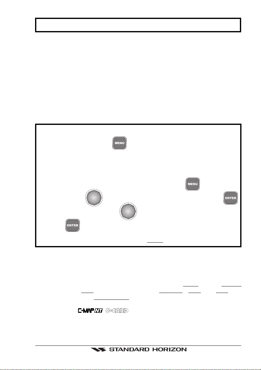
1.2 IF YOU NEED ASSISTANCE
If your chartplotter does not operate properly, go to the System Test on Section 7.1.
Most common operating difficulties can be diagnosed using these tests. If you still
need assistance, call STANDARD HORIZON Product Support or your local Dealer,
reporting the Software System Information
Storage Capacity
Select About Page: 'MENU' + "About..." + 'ENTER'
STANDARD HORIZON Product Support Department may be contacted at
562-404-2700 or via e-mail at marinetech@yaesuusa.com.
available in the About page.
Figure 1.2 - About Page
, Cartography Information and
Page 10 GPS Chart 150

2. ACCESSORIES
2.1 PACKING LIST
When the package containing the chartplotter is first opened, please check it for the
following contents:
• External bracket (includes the knob) - TT150001CP
• Protective cover - RR150002CP
• Power data cable - TT90000001
• Flush mounting Screws - UU90000001
• Flush mounting Template - RR15000001
• Antenna - QQ150001CP
• 1 amp fuse and holder (see Section 4.1.3 for wiring) - Q0000002
• Owner's Manual - EECP150001
• Quick Reference guide - EECP150002CP
• Handbook - EE150002EP
2.2 OPTIONS
• Overhead Mounting Bracket - RR150003CP
Figure 2.2 - Bracket
If any parts are missing contact the Dealer this chartplotter was purchased from.
Accessories and Replacement parts may be ordered from STANDARD HORIZON's
parts Department at 562-404-2700 Ext 351 or via the web at www.standardhorizon.com.
are available through your local marine Dealer. For additional
information on C-MAP Cartography contact 800-424-2627 or visit web site at
www.c-map.com.
GPS Chart 150 Page 11
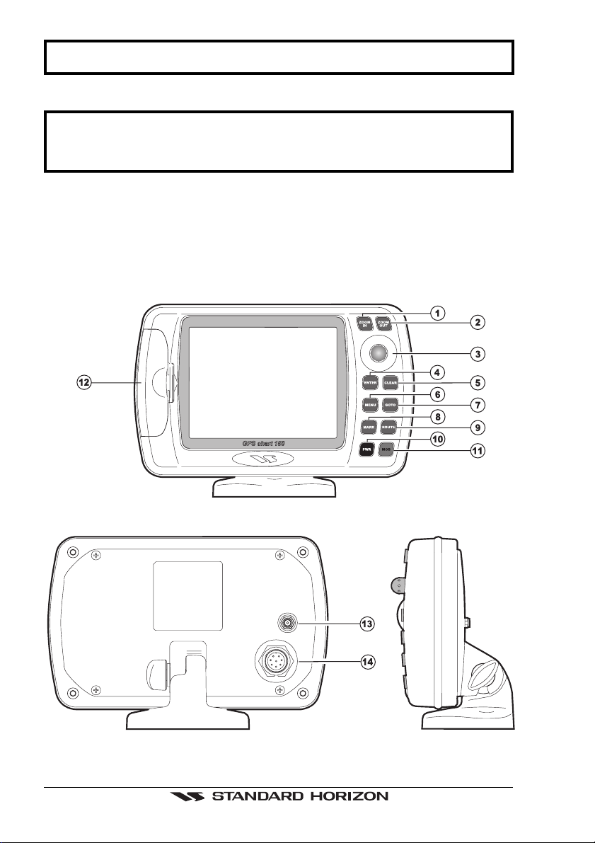
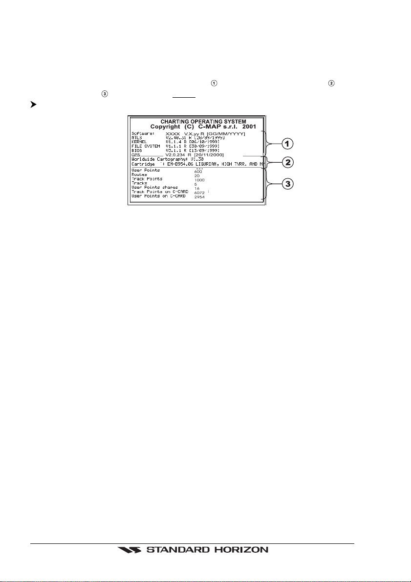
3. CONTROLS AND INDICATORS
NOTE
This Section defines each control of the chartplotter. For detailed operating
instructions, refer to Section 8 of this manual. Refer to Figure 3.1 for the location
of the following keys and connections.
3.1 CONTROLS AND CONNECTIONS
The chartplotter is controlled by using 10 keys. There is also a
move a cursor across the screen. As you press a key, a single audio beep confirms
the key action; every time the key pressed is not valid, three rapid beeps sound
indicates that no response is available.
ShuttlePoint
knob to
Figure 3.1 - The chartplotter
Page 12 GPS Chart 150
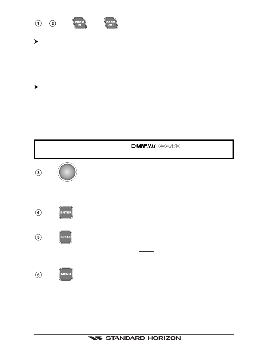
- The and keys
There are two different modes to change chart scale "By Zoom" and "By Scale".
'MENU' + "GENERAL SETUP" + 'ENTER' + "ZOOM TYPE" + 'ENTER' + "By Zoom"
+ 'ENTER'
Pressing the 'ZOOM IN' shows more detail of a smaller area, by changing the chart
scale and zooming in on your display. Press 'ZOOM OUT' to change the scale and
show a wider, otherwise less detailed view. Pressing and holding 'ZOOM IN'/'ZOOM
OUT' allows the quick zoom, that is the fast change of the chart scale where only the land
areas are drawn. When 'ZOOM IN'/'ZOOM OUT' is released all map details are shown.
'MENU' + "GENERAL SETUP" + 'ENTER' + "ZOOM TYPE" + 'ENTER' + "By Scale"
+ 'ENTER'
When 'ZOOM IN' or 'ZOOM OUT' is pressed the chartplotter will show the zoom
window: pressing the 'ZOOM IN'/'ZOOM OUT' or moving the
down moves the scale and bar graph, press 'ENTER' to zoom to the scale. Press
'CLEAR' to quit the zoom window and keep the selected chart scale.
NOTE
ShuttlePoint
knob up/
Due to the cartography contained in the
charts shown within the same scale range.
The
The
ShuttlePoint
accurately. It also scrolls the desired option in the menu page(s). If in Home (Navigate)
mode, it allows to exit from Home mode to cursor mode.
ShuttlePoint
knob moves the cursor about on the display screen, quickly and
knob
there will be multiple
The key
Press 'ENTER' to select the desired option or to confirm selection.
The key
From the chart display press 'CLEAR' to set Home mode. Also press 'CLEAR' to exit
from menu or data windows or to leave a menu without making changes, to abort
selected function or to step backward from a selection made in the menu.
The key
Selects the Main Menu. When in menu mode, moving the
enters a selection, moving the knob to the left clears the function.
If pressing 'MENU' for 3 seconds from map display activates Edit mode to choose data
to be shown in General, 1 Line Small, 1 Line Large or 2 Lines Small windows.
If pressing 'MENU' for 3 seconds from Data pages (Navigation, Highway, GPS Status,
NMEA Display) allows to customize all data fields shown in the selected page.
ShuttlePoint
knob to the right
GPS Chart 150 Page 13
The key
Allows the user to select a Destination point (Target) at the cursor or a saved Route
Mark.
or
The key
Places Mark under the cursor position (in Home mode Mark is placed under the ship's
position).
The key
Places Waypoints to make Routes.
The key and Lamp/Contrast
Press 'PWR' to turn the chartplotter On. Press and hold 'PWR' down (once the
chartplotter has been turned On) for 3 seconds turns the chartplotter Off.
Press and immediately release 'PWR' to adjust light and contrast of the display.
The key
Sets MOB (Man OverBoard).
C-CARD slot (see Section 4.1.7).
GPS Antenna connector
Power and I/O connector (see Section 4.1.2).
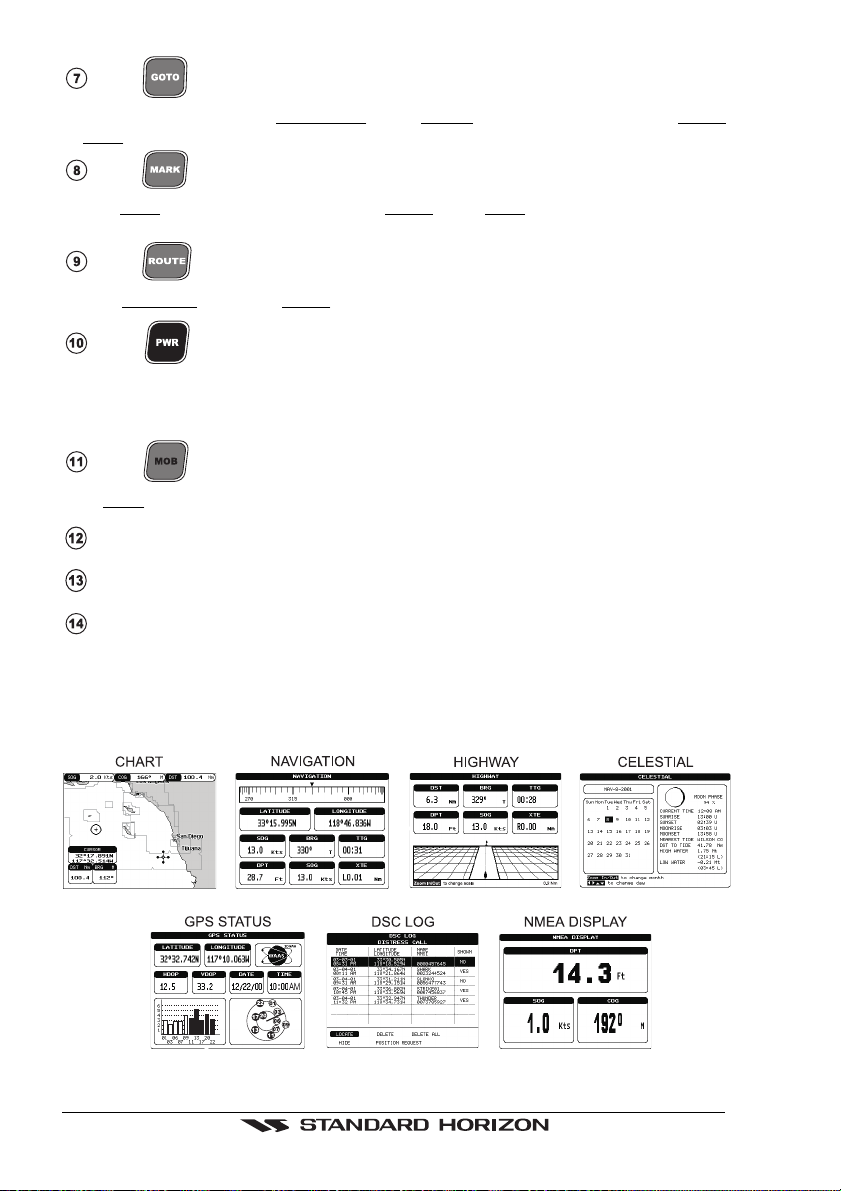
3.2 SCREEN DISPLAY CONFIGURATIONS
The chartplotter display can be shown in different pages among (see following
Sections):
Figure 3.2 - Screen display pages
Page 14 GPS Chart 150
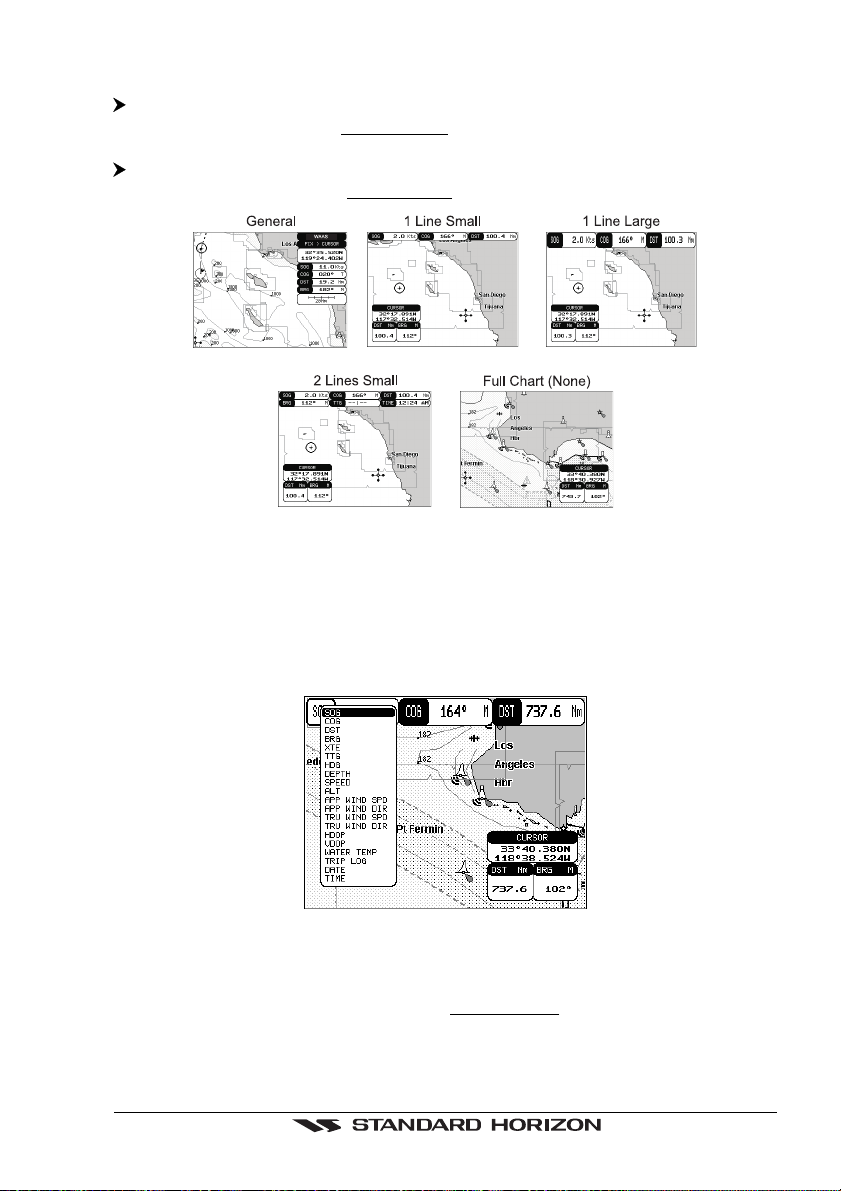
3.2.1 Chart Page
'MENU' + "CHART" + 'ENTER'
Shows the chart display and Data Window (Text Area if selected). With the following
procedure:
'MENU' + "GENERAL SETUP" + 'ENTER' + "DATA WINDOW" + 'ENTER'
it is possible to customize the Data Window layout among (see following Sections):
Figure 3.2.1 - Data window layout
It is also possible to edit fields shown in every screen configuration. Edit mode is
activated directly from the chart display pressing 'MENU' for 3 seconds.
Once the Edit mode is active, the first box with the label turns gray and its frame is
drawn bold. The user can choose the active box by moving the
or right. Pressing 'ENTER' the user can choose the data to be shown on the selected
field by moving through the selections and pressing 'ENTER' again.
ShuttlePoint
knob left
Figure 3.2.1a - Edit mode
If the selected data type can be shown with different units of measure the list of the
units is shown next to it. Once 'ENTER' is pressed the data type and its unit are set.
The selection window is closed and the Data Window changes according to the
selected data type.
Press 'CLEAR' to exit the Edit mode.
GPS Chart 150 Page 15
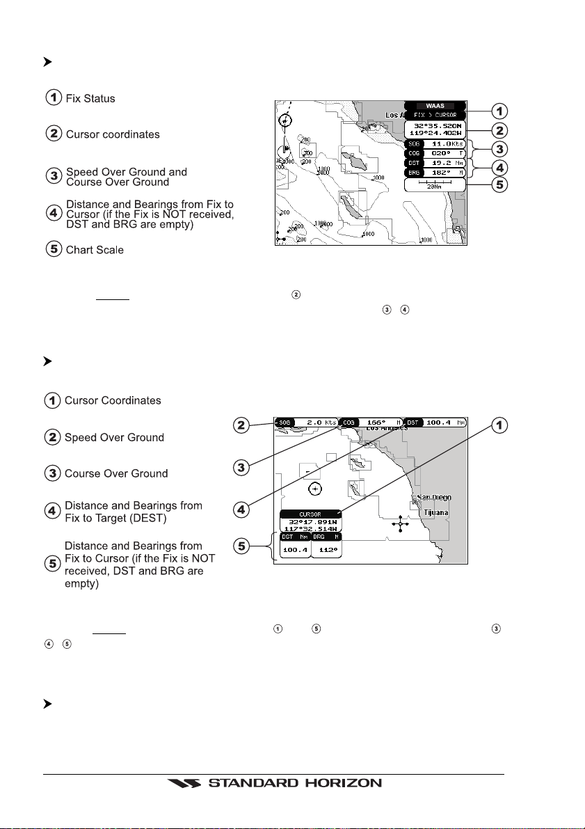
3.2.1.1 General
'MENU' + "GENERAL SETUP" + 'ENTER' + "DATA WINDOW" + 'ENTER' +
"General " + 'ENTER'
Figure 3.2.1.1 - Charts and general text area
When in Home mode the coordinates field shows ship's coordinates; also it is
possible to choose the data to be displayed in the four fields
, .
3.2.1.2 Line text window
'MENU' + "GENERAL SETUP" + 'ENTER' + "DATA WINDOW" + 'ENTER' + "1 line
small /1 line large" + 'ENTER'
Figure 3.2.1.2 - Charts and line text area
When in Home mode the cursor window ( and ) is not shown; the three fields ,
, are selectable fields.
It is possible to use small (1 line small) or large (1 line large) characters to display the
information.
Otherwise it is possible to use small characters on two lines to display information:
'MENU' + "GENERAL SETUP" + 'ENTER' + "DATA WINDOW" + 'ENTER' + "2 lines
small" + 'ENTER'
Page 16 GPS Chart 150
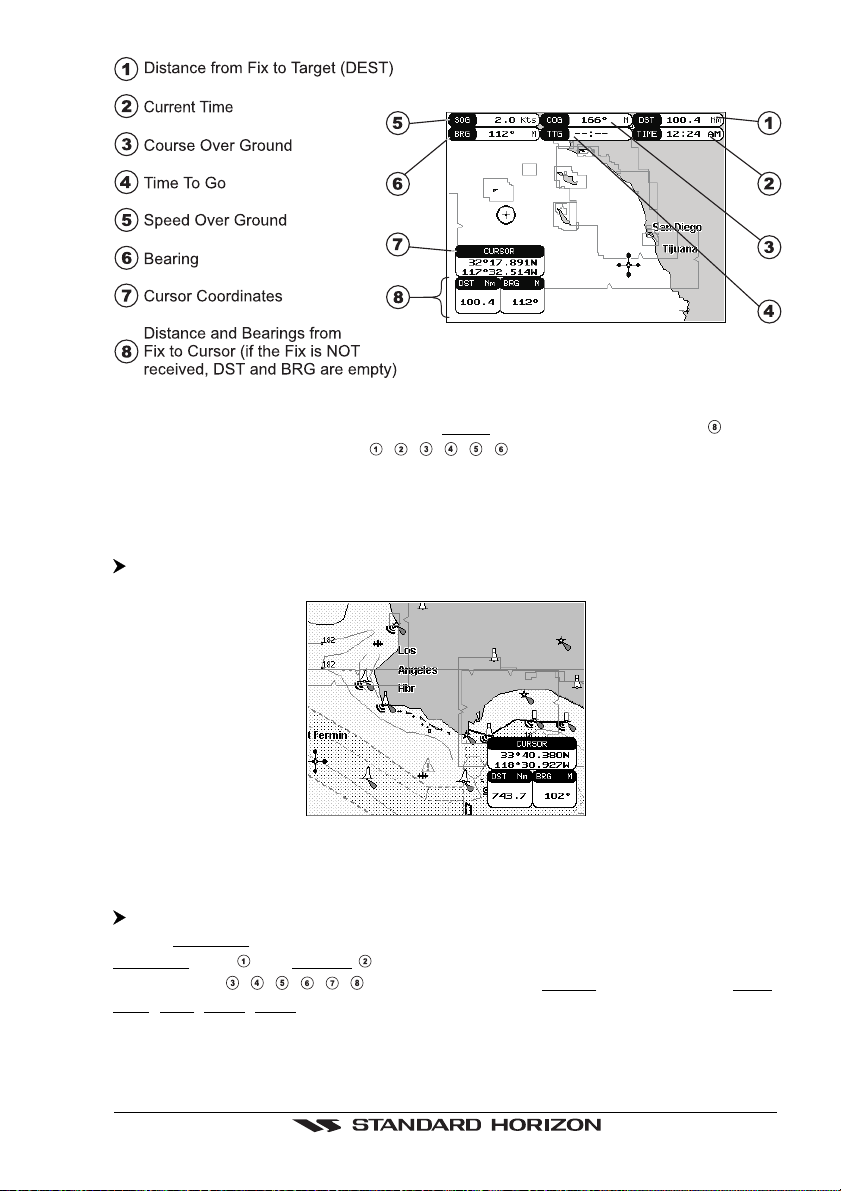
Figure 3.2.1.2a - Charts and 2 lines text area
As in the previous Figure 3.2.1.2, when in Home mode the coordinates field shows
ship's coordinates; the six fields
in the previous Section 3.2.1.
, , , , , are selectable fields as described
3.2.1.3 Full chart
It is also possible to show the cartography at full screen:
'MENU' + "GENERAL SETUP" + 'ENTER' + "DATA WINDOW" + 'ENTER' + "None"
+ 'ENTER'
Figure 3.2.1.3 - Full Map Display
3.2.2 Navigation Data Page
'MENU' + "NAVIGATION" + 'ENTER'
Shows Compass display, fix position and the most relevant navigation information.
Compass ruler and Lat/Lon fields are fixed fields and cannot be changed. The
last six fields (
TTG, XTE, SOG, COG) as described in the previous Section 3.2.1.
, , , , , ) are selectable fields (default values are DST, BRG,
GPS Chart 150 Page 17
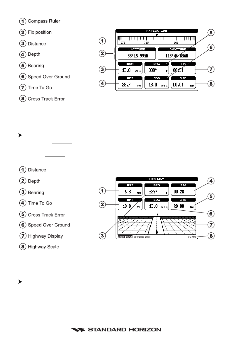
Figure 3.2.2 - Navigation Data Page
3.2.3 Highway Page
'MENU' + "HIGHWAY" + 'ENTER'
Shows the 3D Highway and the most relevant navigation information. It is possible to
customize all fields shown in the page as described in the previous Section 3.2.1. The
scale of the Highway display can be changed by pressing 'ZOOM IN'/'ZOOM OUT'; the
ranges available are 0.2, 0.5, 1.0, 2.0, 4.0, 10.0 Nm.
Figure 3.2.3 - Highway Page
3.2.4 Celestial Page
'MENU' + "CELESTIAL" + 'ENTER'
Shows the Moon phases, Sunrise/Sunset time and Low Water/High Water level at
current location.
The day can be moved in the calendar by moving the
'ZOOM IN'/'ZOOM OUT' to change the month.
Page 18 GPS Chart 150
ShuttlePoint
knob left/right; use
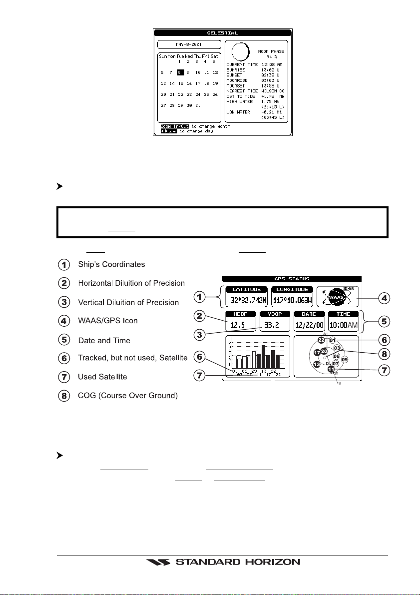
Figure 3.2.4 - Celestial Page
3.2.5 GPS Status Page
'MENU' + "GPS" + 'ENTER'
NOTE
To bypass this screen press 'CLEAR' to revert to the chart.
Screen will
Shows GPS satellites information. This is the default page shown at power on.
default to chart page when fix is received.
Figure 3.2.5 - GPS Status page
3.2.6 VHF Radio DSC LOG Page
'MENU' + "DSC" + 'ENTER' + "LOG" + 'ENTER'
Shows the Distress Call LOG page or Position Request LOG page (it depends which
of the two was selected. The default is Distress Call LOG page). Press 'CLEAR' to
return to chart display.
GPS Chart 150 Page 19
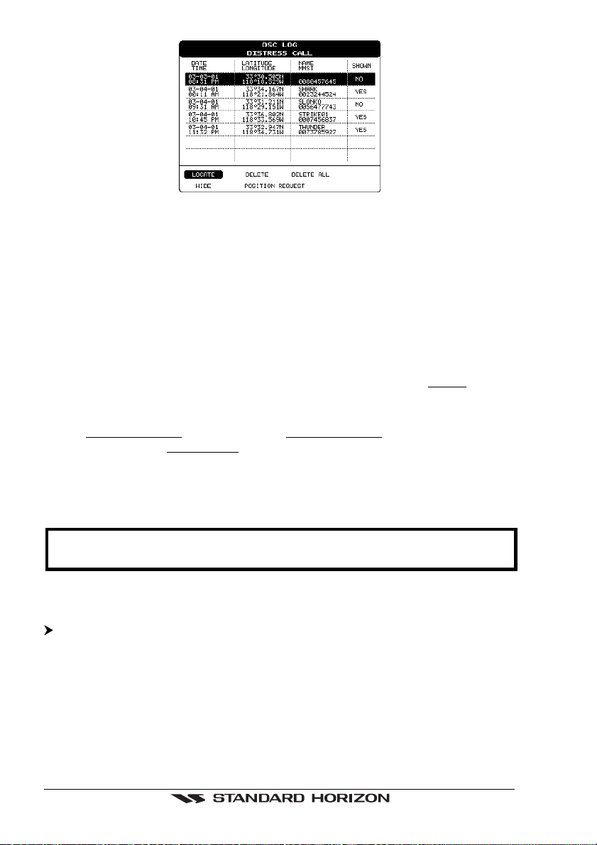
Figure 3.2.6 - DSC LOG - Distress Call Page
Use the
to select active function:
Locate
Centers the map on the selected position.
Delete
Deletes selection position.
Delete All
Deletes all entries.
Hide/Show
Allows hiding/showing the selected points on the chart display. The
the field is Yes (object shown on the map).
Position Request
Shows Position Request LOG page. When Position Request LOG page is active this
message changes to Distress Call LOG page.
ShuttlePoint
knob up/down to move the selection through the list and left/right
default value of
3.2.7 NMEA DISPLAY Pages
NOTE
Certain data fields will not operate unless the chartplotter is interfaced with another
NMEA instrument.
3.2.7.1 Display Page
'MENU' + "NMEA DISPLAY" + 'ENTER' + "DISPLAY" + 'ENTER'
It is possible to choose the page layout (the number of fields in the page) and the type
of data shown in each of the fields in the page as described in the previous Section
3.2.1. If the selected type of data is not received the field shows dashes.
Page 20 GPS Chart 150
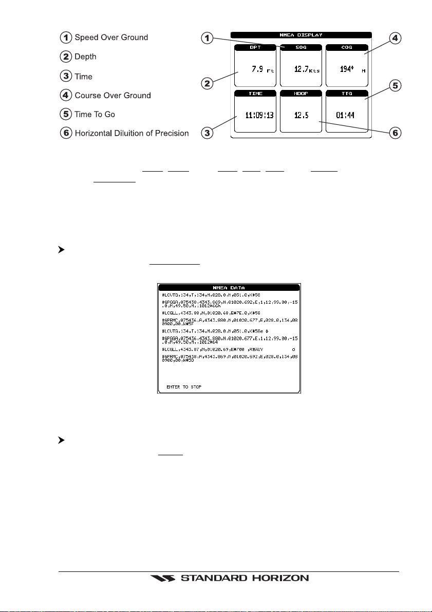
Figure 3.2.7.1 - NMEA DISPLAY Page
Data selectable are: SOG, COG, DST, BRG, XTE, TTG, ALT, HDOP, VDOP, BOAT
SPEED, HEADING, DEPTH, TRIP LOG, WATER TEMP, TRUE WIND SPEED, TRUE
WIND DIRECTION, APPARENT WIND SPEED, APPARENT WIND DIRECTION.
To change pages move the
ShuttlePoint
knob to the left or to the right.
Press and hold 'MENU' for 3 seconds to change the data fields in the windows.
3.2.7.2 Data Page
'MENU' + "NMEA DISPLAY" + 'ENTER' + "DATA" + 'ENTER'
Shows the stream of NMEA-0183 sentences read from the NMEA port. Pressing
'ENTER' stops/starts alternatively the page update.
Figure 3.2.7.2 - NMEA Data Page
3.2.7.3 Depth Trend Page
'MENU' + "NMEA DISPLAY" + 'ENTER' + "DEPTH TREND" + 'ENTER'
Shows the graph of the Depth received from the NMEA Port. Pressing 'ZOOM IN'/
'ZOOM OUT' changes the time scale.
GPS Chart 150 Page 21
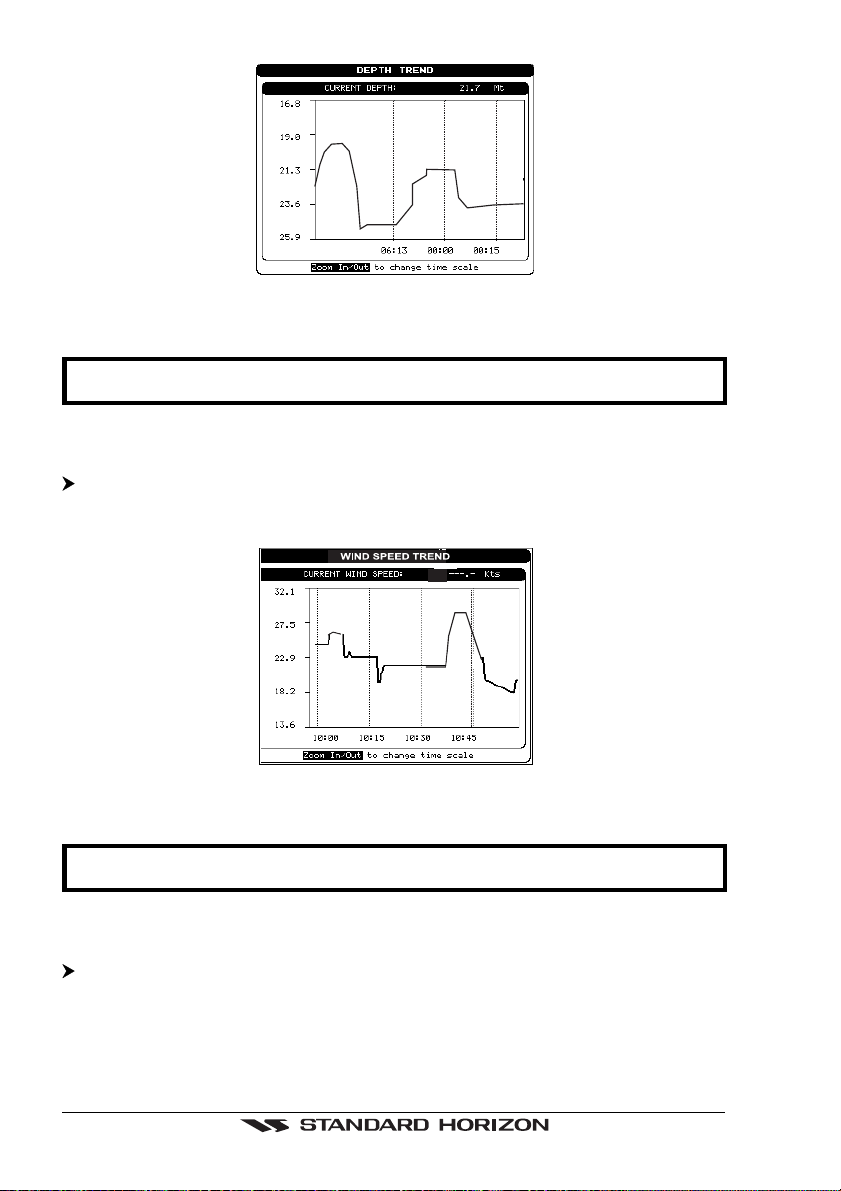
Figure 3.2.7.3 - Depth Graph Page
NOTE
Changing time scale will delete all points on the graph.
3.2.7.4 Wind Speed Trend Page
'MENU' + "NMEA DISPLAY" + 'ENTER' + "WIND SPEED TREND" + 'ENTER'
Shows the graph of the Apparent Wind Speed received from the NMEA Port. Pressing
'ZOOM IN'/'ZOOM OUT' changes the time scale.
Figure 3.2.7.4 - Wind Speed Graph Page
NOTE
Changing time scale will delete all points on the graph.
3.2.7.5 Temp Trend Page
'MENU' + "NMEA DISPLAY" + 'ENTER' + "TEMP TREND" + 'ENTER'
Shows the graph of the Water Temperature received from the NMEA Port. Pressing
'ZOOM IN'/'ZOOM OUT' changes the time scale.
Page 22 GPS Chart 150
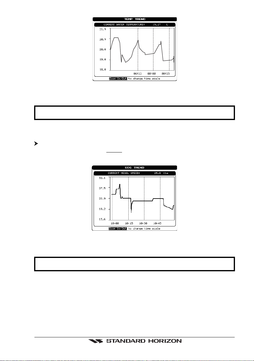
Figure 3.2.7.5 - Temp Graph Page
NOTE
Changing time scale will delete all points on the graph.
3.2.7.6 SOG Trend Page
'MENU' + "NMEA DISPLAY" + 'ENTER' + "SOG TREND" + 'ENTER'
Shows the graph of the vessel Speed received from the NMEA Port. Pressing 'ZOOM
IN'/'ZOOM OUT' changes the time scale.
Figure 3.2.7.6 - SOG Graph Page
NOTE
Changing time scale will delete all points on the graph.
GPS Chart 150 Page 23
4. OPERATION
4.1 INITIAL SETUP
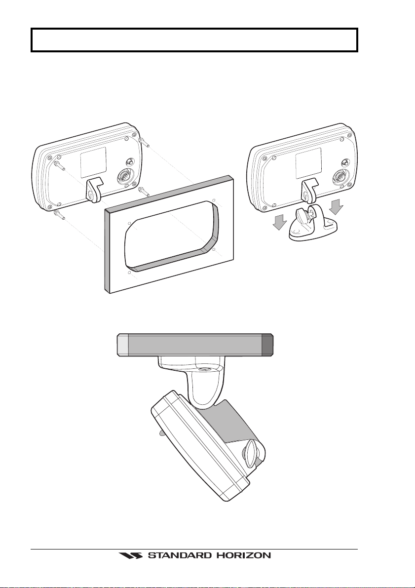
4.1.1 Installing/Removing chartplotter
Figure 4.1.1 - Installing/removing chartplotter
Figure 4.1.1a - Optional overhead mounting bracket
Page 24 GPS Chart 150
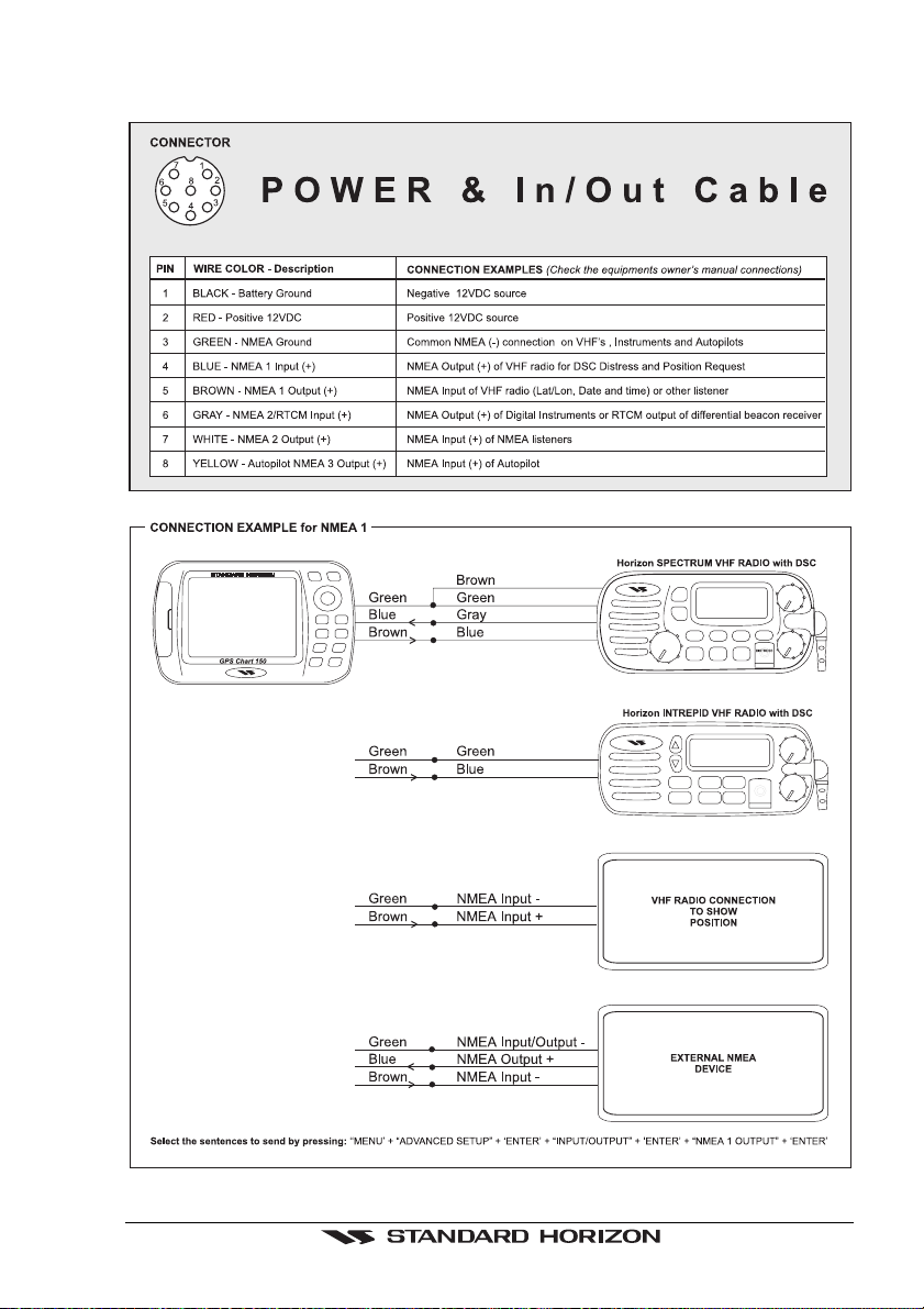
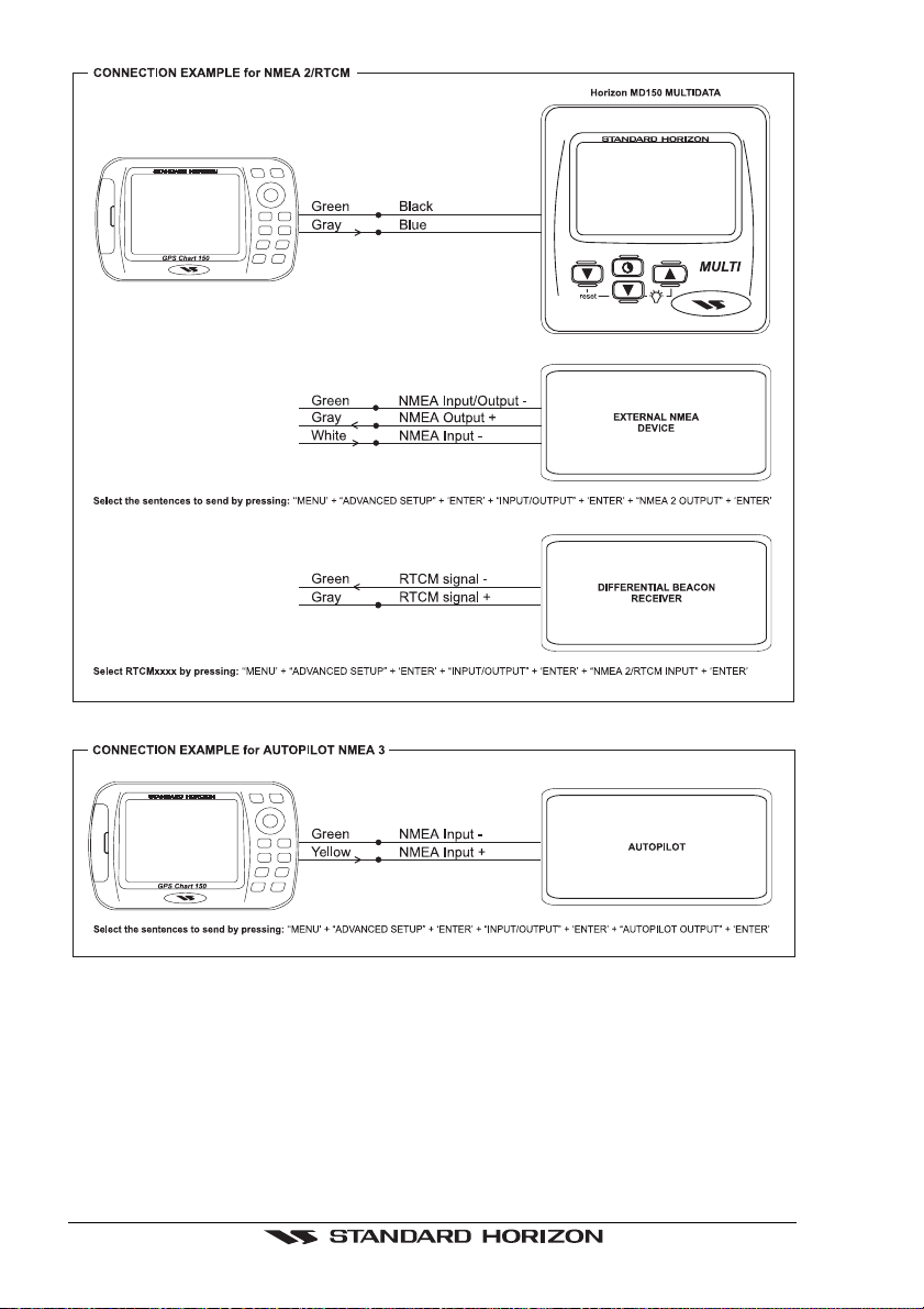
4.1.2 Cable Wiring
GPS Chart 150 Page 25
4.1.3 Turning the chartplotter On and Off
Before powering On the chartplotter, check for the correct voltage (10-18 volt dc), the
correct polarity and be sure that the supplied 1A Fuse is wired in series on the PWR (Black) wire:
Page 26 GPS Chart 150
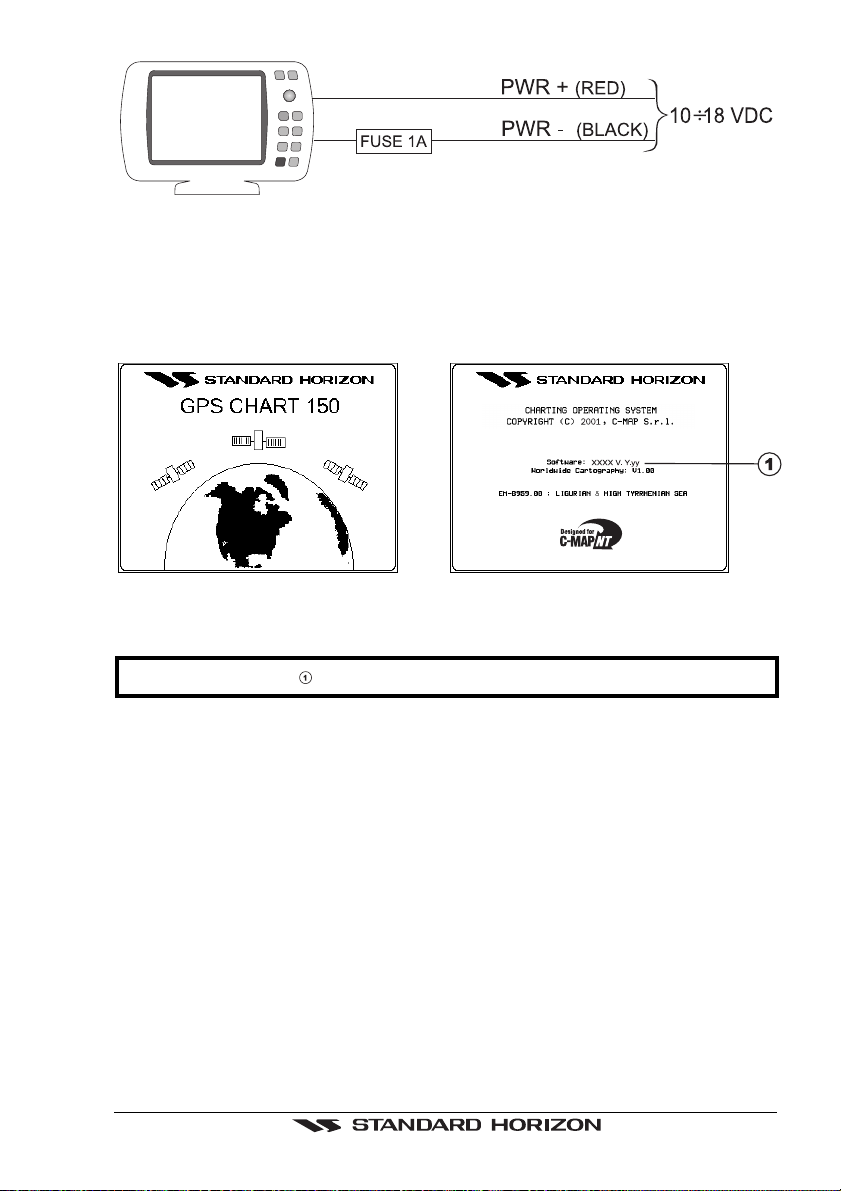
Figure 4.1.3 - Power On
Check also for the correct connection of the GPS antenna.
4.1.3.1 Turning On
Press and hold 'PWR' for 1 second. The chartplotter emits one rapid beep sound and
the Start-Up pages are opened:
Figure 4.1.3.1 - Start-Up pages
NOTE
The software version is subject to change without notice.
After a few seconds, the first of the two Caution Notice pages is displayed, reminding
you that the chartplotter is only an aid to navigation, and should be used with
appropriate prudence. The electronic charts are not intended to substitute official
charts. Then the cartographic screen is displayed.
4.1.3.2 Turning Off
Press 'PWR' and hold for 3 seconds: a countdown timer appears on the screen, if you
release the key before the countdown timer reaches zero, the chartplotter will remain
On.
4.1.4 Changing Light and Contrast
Press and immediately release 'PWR' (do not press and hold the key, or the "poweroff" message will be displayed!): use the
light (move it left/right) and the contrast (move it up/down). Press 'ENTER' to confirm
the setting.
GPS Chart 150 Page 27
ShuttlePoint
knob to increase/decrease the
 Loading...