

Page 1
Minimum System: 133 MHz w/ Win 95/98; 32 MB RAM
Options:
AES/EBU I/O: AES/EBU I/O connects to S/PDIF I/O
19” 2U MONO Rack: MONO RACK for 1 DIRECT PRO 24/96
19” 2U DUAL Rack: DUAL RACK for 2 DIRECT PRO 24/96
The Direct Pro 24/96 Package Includes:
• Direct Pro 24/96 Break-Out Box
• Direct Pro 24/96 Host PCI Card with DSP
• Direct Pro 24/96 Manual
• Custom 25-pin Shielded Cable
• Software Control Panel
• Windows 95/98 and ASIO Drivers
• Multichannel Recording Application and Effects**
** For updated software bundle check out our website: www.aardvark-pro.com/DirectPro/software
Phantom Power: 48Vdc, max current: 40mA
Analog Outputs: Four Line Outputs on 1/4" Connectors: +4 dBu/-10 dBv
Headphone Output: Stereo Headphone Jack on front
Digital I/O: 24 Bit S/PDIF In/Out, OPTIONAL: AES/EBU In/Out
MIDI I/O: MIDI In/Out on 5-Pin DIN Connectors
Sync I/O: S/PDIF Digital Clock, MIDI
Modes: Full Duplex Simultaneous Record/Play
Expansion: Up to four (4) cards can be used simultaneously in one PC.
Computer Card Type: PCI Bus Architecture, 5" length
Connectors on Card: 25-Pin Connector to Break-Out Box, S/PDIF Digital In/Out
Powerful DSP: 24 Bit, 80 MIPS
• 1/4" Bal Line Inputs at +4 dBu (w/ 30 dB Level Trim)
Two AUX Outputs on RCA Connectors: -10 dBv
Analog Inputs: Four Combo 1/4" & XLR Connectors:
• Frequency response at -3db: 1.6Hz-200kHz
• EIN at 20-20kHz, 150 Ohm: -130dBu
• 1/4" UnBal Line Inputs at -10 dBv (w/ 30 dB Level Trim)
• XLR MIC Inputs (w/ 60 dB Level Trim) & Phantom Power
• THD at 20db gain: 0.0005%
Direct Pro 24/96 Specifications, Options, & Components
Direct Pro 24/96 Specifications:
Converters: 24 bit, 96 kHz A/D D/A Shielded Converters
THD+N: .002% @ 1 kHz
Dynamic Range: 110 dB D/A, 100 dB A/D
Frequency Response: 7 Hz-44 kHz, +/- .5 dB at 96 kHz
Sample Rates: 32 kHz, 44.1 kHz, 48 kHz, or 96 kHz
Mic Preamp: Discrete, 8 transistor/channel design
Direct Pro 24/96 Owner’s Manual
Page 2

to correct the interference at his own expense.
2
tion!
FCC Statement
This equipment has been tested and found to comply with the limits for a class A
digital device, pursuant to part 15 of the FCC rules. These limits are designed to
provide a reasonable protection against harmful interference when
the equipment is operated in a commercial environment. This
equipment generates, uses, and can radiate radio frequency and, if not
installed and used in accordance with the instruction manual, may cause harmful
interference to radio communications. Operation of this equipment in a residential
area is likely to cause harmful interference in which case the user will be required
The Philosophy
The All-In-One Direct Pro 24/96 is truly a revolution in PC recording. This Personal Studio System is a
clever combination of hardware and software that provides professional recordings right out of the box, all
while keeping the audio quality and computer performance to the expectations of the world’s top profes-
sional studios.
Because the Direct Pro 24/96 is an all-in-one system, it eliminates the need to purchase an expensive
mixer to record your audio on the PC. The break-out box, software and powerful DSP engine allow you to
have all the meters, faders, pan adjustments, input level trim, EQs and mic pre-amplifiers that expensive
mixers have. In addition, you get the flexibility of presets and one-touch adjustments to make the whole
system more efficient.
We also know that monitoring with effects is crucial in getting good recordings, so the effects delay
doesn’t get in the way of your creative spirit. That’s why we’ve included a powerful DSP engine and three
real-time DSP effects so you can monitor in real-time without the 1/2 second latency that you’ll find in
almost all other PC recording systems. The DSP not only gives you great sounding real-time effects, but it
also completely powers the Direct Pro 24/96 system so it keeps your PC running lightning fast.
We hope you notice all the extra effort we put into the Direct Pro 24/96. The hand-crafted mic preamplifi-
ers, perfectly shielded PCI card and our easy to use Control Panel should make using the Direct Pro 24/96
a refreshing beginning to many years of PC recording.
We welcome you to the Aardvark family and hope you enjoy being part of the new PC recording revolu-
• One Available PCI slot
• Microsoft Windows 95 or Windows 98
• Pentium or compatible of running at 200Mhz or higher
• 64 MB RAM
Welcome to the Direct Pro 24/96, the All-in-One professional studio PC interface!
System Requirements
Introduction Troubleshooting Guide (cont'd)
complies with
requirements.
European CE
This product
Direct Pro 24/96 Owner’s Manual
Check your Source Select indicator settings in the Direct Pro 24/96 control panel. When recording S/
PDIF, the Source Select should be set to S/PDIF.
only the Direct Pro 24/96’s monitoring capabilities.
Problem: Jitter is present on digital S/PDIF recordings
Direct Pro 24/96’s input monitoring, so if you combine the signals, echoing will result. To avoid this, use
This can occur if you use the Direct Pro 24/96’s monitoring capabilities at the same time as the monitor
from your audio software. There will be a longer delay with the software monitored tracks than with the
the Direct Pro 24/96 drivers.
Problem: Some of the inputs or outputs aren’t functioning
Make sure that the inputs and outputs are being properly routed in the Direct Pro control panel. Refer to
the Patch Bay section of this manual for more information on how to do this. Also, check the connec-
tions between the Aark interface box and your outboard equipment. If the inputs or outputs are still not
working, contact Aardvark technical support (tech@aardvark-pro.com)
Problem: The Direct Pro 24/96 is having or is causing an IRQ conflict.
Although Windows assigns and IRQ position to the Direct Pro 24/96, the IRQ is not actually used. For
this reason, any other peripheral can share the same IRQ without performance problems, even if win-
dows warns of a conflict.
Problem: The Direct Pro 24/96 sample rate switches to 32kHz for no reason.
This problem will occur if the Direct Pro 24/96 is being used by Windows to play system sounds. You
can assign these sounds to another sound card by going to Start Menu/Settings/Control Panel/Multi-
media, and selecting the other card as the Preferred Device for Playback and enabling Use Preferred
devices only. Otherwise, you should disable the sound by going to Start Menu/Settings/Control Panel/
Sounds and selecting No Sounds from the Schemes dropdown menu.
Problem: Echo is present when monitoring tracks
This situation may result if you have previously installed audio hardware from other manufacturers (such
as Event Electronics) that use Motorola chipsets for PCI access. You must remove the previous device
driver by opening the folder C:\Windows\Inf\Other, searching for the file name that matches the previ-
ous audio hardware, and deleting it. Next, in Start Menu/Settings/Control Panel, open the System con-
trol panel and select the Device Manager tab. Open Sound, Video, and game controllers, select the
previous audio hardware and click Remove followed by Refresh. Windows should now begin installing
35
Page 3

34
Problem: The Direct Pro 24/96 isn’t working after a reboot
Because the Direct Pro 24/96 is directly powered from the computer, there are major advantages such
as reduced ground loop potential and a complete absence of transformer noise. However, this also means
that the Direct Pro 24/96 requires a full PCI bus reset when the computer is rebooted. A complete
restart is needed to achieve this, and some computers may require the power turned off before booting
to do this. If the PCI bus has not properly reset, you may see an error message such as “Direct Pro 24/96
alert- Unable to send software to host card” or “The Aark hardware is not responding”, the direct pro will
not function until you reset the PCI bus by rebooting.
Problem: The Direct Pro 24/96 does not seem to be functioning
Make sure the software is correctly installed by doing to Start Menu/Programs/Aark Manager and se-
lecting Aark Manager. If this software is not installed, please refer to the installation section of this manual.
Otherwise, turn off your computer, unplug the power cable and open the cover. Discharge any static by
touching a bare spot on the metal chassis, then make sure the Direct Pro Host PCI card is firmly in place.
Put the cover on and start your system. If the Direct Pro 24/96 is still not working, try putting the Direct
Pro Host PCI card in another slot, swapping cards if necessar y. Firmly reseat the card and screw it into
place, then reattach the interface cable, replace the cover, and boot the computer, following the instruc-
tions from the installation section.
Problem: Windows won’t install the Direct Pro 24/96 Driver
feature and Office Startup Assistant. Any of these tasks can interfere with playback or recording.
8. Deactivate any background tasks such as screensavers, crash protectors,
DirectCD discs may not read correctly while this setting is disabled.
virus scanners and disk compression agents. If Microsoft Office is installed, disable the Fast Find
7. In the System control Panel, Click on the Device Manager tab. double-click the CDROM header,
select your CD-ROM drives. Click on Properties, select the Settings tab, and disable Auto Insert
Notification. This can prevent problems with playback and recording. Please note that Adaptec
6. CD-ROM drives and older hard drives should be located on the secondary IDE channel, away from
specialist to resolve this situation.
your newer hard drives on the Primary channel. Mixing fast and slow drives on the same channel
can lower performance.
5. At the bottom of the performance tab, you should see Your system is configured for optimal perfor-
Troubleshooting Guide (cont'd) Table of Contents
mance. Any other messages will alert you that there is an underlying problem with your system
configuration, potentially causing performance problems. If this is the case, consult a computer
Direct Pro 24/96 Owner’s Manual
Direct Pro 24/96 Troubleshooting Guide ............................................................................... 33
Direct Pro 24/96 Specifications.... ........................................................................................... 36
Cubase ............................................................................................................................... 30
Cakewalk .......................................................................................................................... 31
Direct Pro 24/96 Quick Start Guides ....................................................................................... 30
Samplitude Basic ............................................................................................................ 29
Patch Bay .......................................................................................................................... 27
Advanced Menu .............................................................................................................. 26
Presets ............................................................................................................................... 26
Monitor Controls ............................................................................................................. 25
Playback Channel Controls ........................................................................................... 24
Direct Pro 24/96 Control Panel................................................................................................. 16
Rear Panel............................................................................................ ............................. 15
PCI Card............................................................................................................................. 15
Input Strips.......................................................................................... ............................. 16
Effects ................................................................................................................................ 19
Direct Pro 24/96 Interface Box ................................................................................................. 14
Front Panel........................................................................................................................ 14
Software Setup ............................................................................................................... 12
Windows 98 Setup Guide ..........................................................................................................10
Hardware Setup .............................................................................................................. 10
Software Setup ................................................................................................................. 8
Windows 95 Setup Guide ............................................................................................................ 6
Hardware Setup ................................................................................................................ 6
Table of Contents
Introduction. .................................................................................................................................... 2
Contents ........................................................................................................................................... 3
Direct Pro 24/96 Components .................................................................................................... 4
Installing the Direct Pro 24/96 Hardware ................................................................................ 5
3
Page 4

4
Fax: 734-665-0694
THE DIRECT PRO 24/96 SYSTEM
The Direct Pro 24/96 box should contain all of the following items:
• 1 Direct Pro 24/96 PCI host card
Connects directly to the motherboard of your computer
• 1 Direct Pro 24/96 Interface Box
• 1 6’ shielded 25-pin cable
• 1 Direct Pro Driver CD-ROM
• 1 Digital Audio Software CD-ROM
• 1 Direct Pro 24/96 Manual
If any items are missing or damaged, please contact your dealer or Aardvark Customer Support.
Email: Support@aardvark-pro.com
Tel: 734-665-8899
Direct Pro 24/96 Components Troubleshooting Guide
Direct Pro 24/96 Owner’s Manual
greatly reduce “swap file thrashing”, and improve overall system performance.
my own virtual memory settings. Choose the hard disk with the best performance, set the minimum
to 50 MB (making sure there is at least 75 MB available), leaving the maximum alone. This will
4. Still in the System Performance area, click the Virtual Memory button and activate Let me specify
3. If you are using a Matrox PCI graphics card, click the Graphics button and set Hardware Accelera-
drives with a check mark and click OK. This will reduce the possibility of data corruption following a
crash.
tion to the third setting (Most accelerator functions). This will reduce the potential loss of PCI through-
put to the graphics card.
2. In Start Menu/Settings/Control Panel, select System and click on the Performance tab. Click the
File System button and set Typical Role of This Machine to Network Sever. Read ahead optimization
should be set to Full. Click the Troubleshooting tab, activate Disable write-behind caching for all
defragment them. This procedure should be repeated at least once a week for optimal disk perfor-
mance
64 MB of RAM and a Mode 4 EIDE hard drive. In addition, your motherboard should be PCI 2.1 compli-
ant, and your graphics card should be AGP or PCI with a minimum of 2MB DRAM, VRAM or WRAM.
Many performance problems can be attributed to poor throughput stemming from an older motherboard
or standard IDE hard drive. If your system does not exceed the minimum recommended requirements,
consider upgrading as soon as you can. Audio software requires a great deal of power, and many older
machines simply cannot handle it.
Another possible cause of poor performance is using your system for a wide variety of applications. It is
best to dedicate your system to audio as much as possible, avoiding shell extensions such as Internet
Explorer, Microsoft Office, Norton Navigator, and background virus scanners. These, and many other
programs, have elements running at all times, taking up valuable resources. Press Ctrl-Alt-Del to see
what programs are running in the background. You may be surprised!
Here are some tips for optimizing your workstation:
1. In Start Menu/Programs/Accessories/System Tools, select Disk Defragmenter (unless you have
another defragmentation program such as Norton SpeedDisk). Select all of your hard drives and
DIRECT PRO TROUBLESHOOTING GUIDE
Should you run into any difficulties with your Direct Pro 24/96, please consult this section. Although most
problems are easily rectified this way, do not hesitate to contact Aardvark Technical Support, or check our
website for up to date information.
Problem: Unable to achieve full 4 input/6 output performance.
In order to get the most out of the Direct Pro 24/96, you should have at least a 166 MHz processor with
33
Page 5
click the Stop button and save the file with Save As from the file menu. Clicking the play button will play the
sound file back through the stereo output set in the Preferences dialog.
stereo file at a time, you will only utilize one input and one output pair with these programs. In sound
Forge/ WaveLab, click the red Record button. Enable Monitor in Sound Forge or Meter in WaveLab with a
check mark to view the input level meter, hit record then play your audio. When the recording is complete,
stereo pair for playback and recording. Since Sound Forge and WaveLab can only record or play one
To prepare Sound Forge or Wavelab for recording, open the Preferences dialog from the Options menu.
Click on the Wave tab in Sound Forge, or the AudioCard tab in WaveLab, and select a Direct Pro 24/96
Sound Forge and WaveLab
circle in it.
lar. The correct button has a black box with a red
record mixer automation button, which looks simi-
the top of the screen. Do not confuse this with the
5. Initiate recording by clicking the record button near
click the R button above a track’s volume slider.
record that track. To change inputs, simply click
that button. To arm a track for recording, simply
button that indicates what inputs are used to
you add. At the bottom of each strip, there is a
until you have your desired number of tracks. A
new strip will appear on the mixer for each track
mixer will bring up a menu that provides the op-
tion to add an audio track. Repeat this command
Sound Forge and Wave Lab Installing the Direct Pro 24/96 Hardware
Direct Pro 24/96 Owner’s Manual
the back of the Direct Pro 24/96
interface box labeled To Aark
Host. Tighten the screws to as-
sure a firm connection and maxi-
mum grounding for the Direct Pro
24/96 system.
Host Card, and the other end on
shielded cable to the 25 pin con-
nector on the Direct Pro 24/96
8. Connect one end of the 6-ft
outer cover to lock the Direct Pro
24/96 Host Card in place while
6. Use the screw from the small
seated tightly, with the metal con-
nection bracket matching up per-
fectly through the hole in the back
of the computer.
7. Replace the computer’s cover.
providing maximum grounding.
firmly into place. It should be
PCI Host Card with the chosen
PCI slot and press it slowly but
INSTALLING THE DIRECT PRO 24/96 HARDWARE
PCI host card . Connecting or disconnecting the hardware with electricity present will cause physi-
cal damage to the Direct Pro 24/96 or your computer. It is best to disconnect the power cable
1. Please unplug you PC before connecting or disconnecting the Direct Pro 24/96 interface box and
2. Remove the cover from your computer. Most computers have a series of screws on the back of the
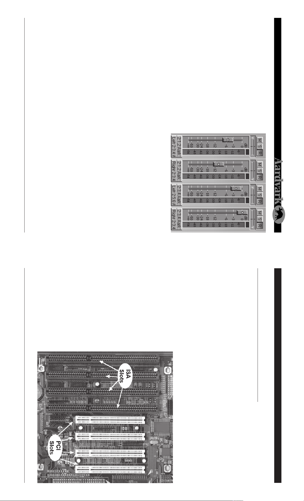
3. Choose an empty PCI slot, it will look like the PCI slots show below.
4. Remove the small outer cover from the chosen PCI slot. This cover will likely be held in place by a
5. Gently align the Direct Pro 24/96
completely before proceeding. If you are unfamiliar with installation of computer peripherals, please
seek assistance from qualified computer technician. Aardvark will not be held responsible nor liable
for damages resulting from improper installation.
screw. Ground yourself by touching an empty slot on the computer’s metal chassis.
case that keeps the cover in place.
532
Page 6
6
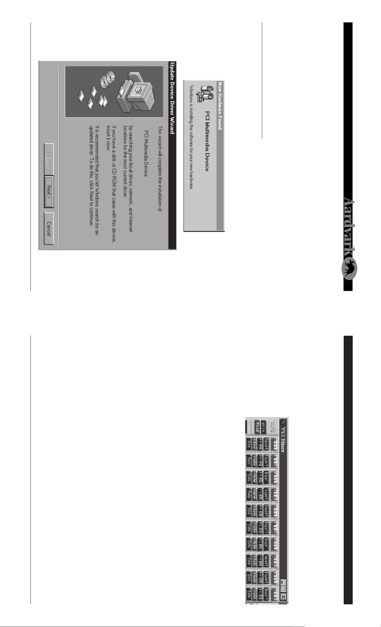
Windows will indicate detecting the hardware with these dialogs:
will identify itself as a “Plug and Play” device.
WINDOWS 95 HARDWARE SETUP
1. When windows restarts, it will automatically detect the card you installed. Since it is a PCI card, it
11. Reconnect the computer’s power supply, then turn on the computer. The Direct Pro 24/96 system
is completely powered by your computer. Because of this, you must never detach the shielded inter-
face cable without first turning off the computer. Otherwise, damage will occur.
interference and degrade the quality of the audio.
Windows 95 Hardware Setup Cakewalk Pro Audio
9. Avoid putting the Direct Pro 24/96 interface box near your computer or TV screen. This may cause
10. Keep analog cables connected to the Direct Pro 24/96 away from power cords and monitors.
Direct Pro 24/96 Owner’s Manual
4. Go to VIEW | CONSOLE. This will open up the Cakewalk mixer. Right clicking a blank area of the
(Direct Show 5.1) is selected.
3. Go to TOOLS | AUDIO HARDWARE. Make sure Windows Sound Cards
Aark drivers are enabled. On the Advanced tab, make sure Enable Simultaneous Record/Playback
is checked off. Depending on your setup, other settings may need to be changed for optimal perfor-
mance. Click OK to save your settings
and Playback Timing Master should be set to 1,2 Aark24. On the Drivers tab, make sure all of the
2. Open Cakewalk, go to TOOLS | AUDIO OPTIONS. Enter these settings: On the General tab Record
L,R to Output 1,2..
Cakewalk Pro Audio 8.0 +
This is an example of a typical setup for recording multitrack in Cakewalk Pro audio. Cakewalk and the
Direct Pro 24/96 are not limited to this configuration. These instructions pertain specifically to Cakewalk
8.x; steps will vary slightly for other versions.
1. Plug outputs 1-2 into your amplifier/mixer. In the Direct Pro 24/96 patch panel, connect Monitor
play back, while you add more tracks to the project.
11. To add more tracks, disable the tracks just recorded, and enable new ones. The previous tracks will
though, that it is unwise to have it written at the hard drive’s root directory.
begin. (If the Cubase transport controls are not on screen, hit the F12 button to reveal them.) Also,
Cubase may bring up a window asking where it should write the audio. This is up to you. Be aware,
9. Minimize the mixer, and activate the desired audio tracks for recording. Activate a track by highlight-
10. Place the left locator at the desired starting point for recording, and click the red record button to
ing it, and clicking the Enable button on the left.
right clicking it.
and can be changed by
This is located on the
lower portion of the strip,
output is set to Aark 1,2.
8. Go to AUDIO | MASTER
and make sure the master
Channel 1 to IN 1 L, Channel 2 to IN 1 R, Channel 3 to IN 2 R and so on. If you click the IN button on
each channel, you can see the Cubase mixer metering the corresponding input on the Direct Pro
24/96 .
7. Go to AUDIO | MONITOR. This will bring up your monitor mixer. To change inputs for each channel,
hold the CTRL key while clicking the input channel button at the top of each channel strip. Set
31
Page 7

3. In the AUDIO dropdown menu, make sure Disable Audio is not checked off.
4. Go to AUDIO | INPUTS and activate all of the Direct Pro 24/96 inputs with the green buttons corre-
5. Go to OPTIONS | MULTIRECORD, set it to Active.
6. In the main window of Cubase, the first tracks listed should be labeled Audio1, Audio2, etc. If this is
not the case, right click on any musical note in the C column, and select Audio track. This will turn a
MIDI track into an audio track
sponding to each input pair.
ASIO Aardvark Aark Cards. Set Monitoring to Global Disable.
2. Open Cubase and go to AUDIO | SYSTEM. Set Number of Channels to 10. ASIO Device should read
QUICKSTART GUIDES
Sometimes, it can take a while to fully unlock the power of the Direct Pro 24/96 and today’s digital
audio software. However, we know how much you want to start recording. These quick start guides will
allow you to quickly configure your setup for multitrack recording!
Cubase VST 3.5+
This is an example of a typical setup for recording multitrack in Cubase VST. Cubase and the Direct Pro
24/96 are not limited to this configuration.
1. Plug outputs 1-2 into your amplifier/mixer. In the Direct Pro 24/96 patch panel, connect Monitor
L,R to Output 1,2.
Before recording begins, a window may come up asking where to save the audio files. Be sure not to select
the root directory of the hard drive. There are a limited number of files that can be written to the root, and
the program will have more trouble streaming the audio, since it is among many small, non-audio files.
Another window may com up stating buffers are ready. Just click OK
It looks like 3 exclamation points on their side.
Direct Pro 24/96 Quick Start Guides: Cubase Windows 95 Hardware Setup (cont’d)
Here, dropdown menus allow the Play Device and Record device to be selected for each track. Choose
which Direct Pro stereo input pair you want to use for recording and which Direct Pro stereo output you
want to use for playback.
6. Tracks can be armed for recording by clicking the R(number) button for each track. Click the Multi Card
Mode button in the upper left corner of your track window.
7. Click the Record parameter button. It’s the big red circle at the top toolbar. When the Record parameter
window pops up, make sure Playback While Recording is checked off.
8. Begin recording by clicking the multirecord button, which is just to the left of the standard record button.
Direct Pro 24/96 Owner’s Manual
3. Click Next. Windows may now ask for the location of the drivers. If this is the case, specify the CD-
ROM drive (usually D:). Otherwise, simply click Next again. Windows will copy the files from the
Direct Pro 24/96 CD-ROM.
2. Insert the Driver CD-ROM packaged with the Direct Pro 24/96 , and click Next. The Following dialog
should appear:
730
Page 8

WINDOWS 95 SOFTWARE SETUP
appear automatically. If not, go to My Computer, find your CD-ROM drive, and click the setup.exe
icon.
5. Once Windows has finished loading, the Direct Pro 24/96 Control Panel installation program may
8
8. Click the Next button to continue. The Ready to Install!! Dialog should now appear. Click Next again
to begin installation.
7. Setup will allow you to select the Destination Directory. Otherwise, it will put the Direct Pro 24/96
software and drivers in the “C:\Program Files\Aark manager” directory. If you would like the files
elsewhere, simply type the new destination or select Browse to put the files in another directory.
6. Click Next when you see the welcome screen:
4. When the files have been copied, Windows will ask to restart the computer. This is because the files
just installed will not take effect until the next time Windows is loaded. Click NO, since you will restart
the computer after completing the Direct Pro 24/96 software installation in the next section.
Windows 95 Software Setup (cont'd) Samplitude Basic
Direct Pro 24/96 Owner’s Manual
dow should appear. Click on the ? under Mas-
ter Volume + Image. This will bring up a play
parameter window. Set the device to 1,2 Di-
rect Pro then close the window. Now, the
mixer window can be closed as well.
5. Clicking the ? symbol by each track opens
a Track Info window for that particular track.
4. Go to WINDOW | MIXER. A mixer win-
PROJECT(VIP), Select “8 Tracks” under Mono
L & R.
3. Go to FILE | OPEN NEW MULTITRACK
2. Open Samplitude. As soon as it opens,
there will be a Record Parameter window.
Click OK.
SAMPLITUDE BASIC
Samplitude Basic is a feature-filled introduction to the full Sek’d Samplitude line that includes Samplitude
Studio and Samplitude 2496. A complete manual can be found on the Samplitude Basic CD-ROM, along
with a multimedia tutorial that will prepare you for working on any Samplitude project.
This is an example of a typical setup for recording stereo multitrack in Samplitude . Samplitude and the
Aark 24 are not limited to this configuration.
1. Plug outputs 1-2 into your amplifier/mixer. In the direct pro control panel, go to the patchbay, and drag
Monitor L,R to all 3 output pairs.
EXTERNAL MIXDOWN:
If you want to mix down a song through a mixer, routing
the computers output channels to separate outputs, con-
figure the patchbay in this manner.
29
Page 9

If you want to use headphones to hear what is plugged
into your inputs, as well as the tracks you have already
recorded, set up the patchbay like this.
HEADPHONE MONITORING:
Patchbay Configuration Examples
INPUT/OUTPUT MONITOR:
If you want to hear what is plugged into your inputs, as
well as the tracks you have already recorded, through
Outputs 1 and 2, set up the patchbay like this:
to any of the analog line outputs and even the digital output.
In your multitrack software, an input pair input 5,6 will be available as a recording device. This is not
included in the patchbay, and does not correspond to physical inputs on the Direct Pro 24/96 interface
box. Inputs 5,6 are virtual inputs that record your monitor mix. They are also the only way to record our
Reverb.
Most users will make a lot of use of the MONITOR by dragging it to the Headphone Output so they can
monitor their mix in real-time along with all of the effects. This monitor can also simultaneously be sent
and to troubleshoot potential cabling problems. Ever y output pair on the right must have a source on
the left connected to it. If you wish to disable an output pair, drag silence to it.
SILENCE options are provided as diagnostic tools to make sure that your computer is working properly,
Patchbay (Cont’d) Windows 95 Software Setup (cont’d)
Direct Pro 24/96 Owner’s Manual
Note: Always turn off your monitors or speakers when rebooting! Often, the speakers will pop during
startup, causing potential damage!
10. You must now turn your computer off for the change to take place. Instead of restarting, select Shut
Down from the Start Menu/Shut down menu. If you choose restart the installation will not be compete,
and you will have to repeat this process!
9. When the installation is complete, a new folder for the Direct Pro 24/96 Control Panel application
will reside in the destination directory, and a shortcut will automatically appear on the desktop for
easy access.
928
Page 10

10
2. Click Next then select the option Search for the best driver for your device, then click Next again.
Windows will indicate detecting the new hardware with these dialogs:
it will identify itself as a “Plug and Play” device.
Windows 98 Hardware Setup Patchbay
WINDOWS 98 HARDWARE SETUP
1. When Windows restarts, it should automatically detect the card you installed. Since it is a PCI card,
Direct Pro 24/96 Owner’s Manual
These playback channels also directly correspond to the 6 Playback meters on the main Control Panel
page. The MONITOR source is the 2 channel mix (of all input and output signals, plus effects) deter-
mined by the control panel. Finally, the TONE and
channels, which represent the files
that you’re playing back from your
multitrack software application.
inputs (both the mic/line analog in-
puts or digital input if it’s activated).
The next 3 choices are the Playback
sources of audio available. The top
two choices are the physical stereo
The choices on the left side of the
patchbay represent the various
your audio routing with the click of a
mouse.
outputs on the right (notice every-
thing on the right represents a physi-
cal output), you can easily customize
connecting physical cables. By sim-
ply selecting the sources from the left
and dragging them to the physical
don’t have to keep connecting and re-
and re-routing all the signals so you
Patch Bay
By clicking on the ‘Patchbay’ button in the control panel, it opens up a very easy to use system for routing
you want to have 16 or 24 bit audio in these applications. Also, the size in samples of the audio buffers in the
ASIO driver. Higher buffer sizes improve the ability of slower computers to handle a large number of tracks.
• ASIO CONFIGURATION: This is for using the Direct Pro 24/96 with ASIO
please contact Aardvark technical support.
compatible drivers, such as Steinberg’s Cubase VST and Emagic’s Logic Audio. Here, you can select whether
to upgrade your computer. If it reads Error , it means the drivers are unable to communicate with Direct
Pro 24/96 hardware. Turn the system off, and make sure everything is plugged in securely, and the card
is properly in place. Check the windows control panel for possible conflicts, and if the problem persists,
mum performance. If it reads Medium, you will most likely function fine, but it may be difficult to achieve
optimal performance. If it reads Low, your setup may not be suitable for digital recording. You may have
and outputs functioning simultaneously. High indicates that you should have no problems with maxi-
27
Page 11

• PCI BUS EFFICIENCY: shows the potential of your system to function with all Direct Pro 24/96 inputs
you are trying to record S\PDIF without setting the Sync Source to S\PDIF.
• ISSUE WARNINGS ON SAMPLE RATE ERRORS: If activated, the Direct Pro 24/96 control panel will
give a warning if you are trying to play a sample rate not supported by the Direct Pro 24/96, or if your
multitrack software is set to a different sample rate than what is configured in the control panel, or if
Source Select Windows 98 Hardware Setup (cont'd)
Source Select
This lets you select your desired sample rate for recording and playback. This must always correspond
to the selected sample rate in your multitrack software application. Otherwise, playback and recording
will not function properly.
The first four selections (Int 32kHz, Int44.1 kHz, Int 48kHz, Int 96kHz) will make the Direct Pro 24/96’s
internal (Int) clock the master for your system. Unless the Direct Pro 24/96 is slaving to another digital
device, one of the 4 Int settings must be chosen.
The Direct Pro 24/96 can slave to other digital devices via the S/PDIF input on the host card. Selecting
S/PDIF in Source Select will allow you to slave to the device. If you are attempting to record via S/PDIF,
and an internal (Int) sync is selected, unwanted noise will be present in your audio.
The number below the white box is the actual measured sample rate of the system. This value shows the
sample rate of the system which makes it very easy to verify that your system is running exactly at the
rate you need. It is also very handy when locking to external digital sources to make sure the file you’re
loading in is what you expect it to be.
Presets
Because of the versatility of the Direct Pro 24/96, you may have multiple configurations for different situa-
tions. These various configurations can be saved using the preset feature. Individual effect settings can be
saved and recalled by using the effect’s PS button. In addition, the Presets button allows you to save the
configuration of the entire Direct Pro 24/96 software configuration, including effects, fader levels, trim,
syncselection, and patchbay settings.
When you push a preset button, a preset menu will appear. To save an effect, type its name in the textbox
on the left and click add. To recall a preset, double-click the desired preset in the box on the left, then
click recall, and close the window. Compression and EQ can have individual settings for each channel,
so recalling the presets for these effects will only alter the settings of the channel selected.
Advanced Menu
You can access the Advanced Menu by pressing the advanced button on the Direct Pro 24/96 control
panel.
Direct Pro 24/96 Owner’s Manual
tion.
96 Control Panel software in the next sec-
computer after installing the Direct Pro 24/
is loaded. Click NO, since you will restart the
This is because the files you just installed will
not take effect until the next time Windows
Windows will ask to restart the computer.
5. When the installation is complete, you
must press Finish to exit the setup.
the Direct Pro 24/96 driver CD-ROM.
24/96 driver software. Click Next to begin
installation. Windows will copy the files from
4. Windows will now locate the Direct Pro
boxes must be cleared. Click Next.
the Direct Pro 24/96. Place a check mark be-
side CD-ROM drive by clicking on it. All other
3. Insert the driver CD-ROM that came with
1126
Page 12

12
9. Click the Next button to continue. The Ready to Install!! Dialog should now appear. Click Next again
directory.
to begin installation.
8. Setup will allow you to select the Destination Directory. Otherwise, it will put the Direct Pro 24/96
software and drivers in the C:\Program Files\Aark Manager Control Panel directory. If you would
like the files elsewhere, simply type the new destination or select Browse to put the files in another
be done from Windows by opening your CD-ROM drive (usually D: ) in My Computer and double
clicking the Setup.exe icon.
6. IF the welcome screen does not automatically appear, run Setup.exe from your CD-ROM. This can
7. Click Next when you see the Welcome Screen.
WINDOWS 98 SOFTWARE SETUP
Windows 98 Software Setup Monitor Controls
Direct Pro 24/96 Owner’s Manual
made available to record your monitor mix. This is useful for recording the reverb, and bouncing tracks.
this)
• PEAK: When pressed, will display the highest volume that has gone through the monitor
• RESET: Will reset the peak volume to zero.
If you would like to record the monitor mix in your multitrack software, select inputs 5,6 as your record-
ing device. This input pair does not correspond to physical inputs on the breakout box. Instead, it is
• FADERS: Cut or boost the volume of the monitor signal. All faders, input, output and master, deal with
the levels of the monitor signal ONLY. In order for these faders to work, Monitor L,R must be assigned
to an output on your patchbay. (See the Patchbay section for more detailed information on how to do
MONITOR CONTROLS
The monitor channel plays all audio routed in or out of the Direct Pro 24/96 . In order to hear the moni-
tor, it must be routed to a physical output in the patch panel. For more detailed information, please read
the Direct Pro 24/96 Patch Bay section.
25
Page 13

• REVERB SEND: This controls how much of the Master Reverb the channel receives.
• MUTE: Turns off the channel’s signal entirely.
• SOLO: The opposite of mute. Soloing an input channel will mute all other output channels. It will be the only
audible channel.
• PLAYBACK FADERS: These faders allow you to cut or boost the volume of audio routed to the
channel.
Playback Channel Controls Windows 98 Software Setup (cont'd)
Playback Channel Controls
An important thing to note, is that the playback faders are not hard wired to the Direct Pro 24/96’s
outputs. Controls for Playback 1,2 do not necessarily need to correspond to the Direct Pro 24/96’s
outputs 1 and 2.
These playback channels refer to the playback channels recognized in your software. Playback channels
and the Direct Pro 24/96’s physical outputs are separate entities, although they typically work together.
While this may seem complex at first, this versatility allows you to take full advantage of the Direct Pro
24/96’s power!
Direct Pro 24/96 Owner’s Manual
Note: Always turn off your monitors or speakers when rebooting! Often, the
speakers will pop during startup, causing potential damage!
11. You must now turn your computer off for the change to take place. Instead of restarting, select Shut
Down from the Start Menu/Shut down menu. If you choose restart the installation will not be compete,
and you will have to repeat this process!
10. When the installation is complete, a new folder for the Direct Pro 24/96 Control Panel application
will reside in the destination directory, and a shortcut will automatically appear on the desktop for
easy access.
1324
Page 14

14
higher than 150 ohm will sound softer.
WARNING: All line level connections MUST use the 1/4” input. XLR inputs are ONLY for microphones.
If the inputs are used incorrectly, damage may occur!
Phantom Power
The phantom power on/off switch activates phantom power for all 4 XLR inputs. Phantom power is not
delivered to the 1/4" input.
Headphone Jack
The headphone output enables you to monitor the audio without speakers.
Note: The headphone Jack is optimized for 60-150 ohm headphones. Headphones with impedance
phones.
The combo jacks accept either 1/
4", or XLR mic connectors. The
1/4" inputs can accept either bal-
anced (+4dBu) or unbalanced (-
10dBV) signals. The XLR jacks
have built-in preamps with 60 dB
level trim. In addition, they are
equipped with an invariable 48V phantom power, allowing you to power professional condenser micro-
puts, MIDI IN and MIDI OUT jacks, and a headphone jack for monitoring. Additional S/PDIF IN and S/PDIF
OUT jacks are on the Direct Pro 24/96 PCI host card.
Front Panel
The Direct Pro 24/96’s front panel
consists of 4 analog combo jack
inputs, a headphone output, and
phantom power controls.
The Direct Pro 24/96 interface box houses 4 shielded analog combo jack inputs, 6 shielded analog out-
DIRECT PRO 24/96 INTERFACE BOX
Direct Pro Interface Box - Front Input Volume Faders (cont’d)
Direct Pro 24/96 Owner’s Manual
In this case, the digital peak meter shows the value of the dry signal that is being sent to the computer for
recording. The volume fader changes the volume of that track and sends it to the MONITOR bus. This
meter is before the fader (pre-fader) so if you move the volume fader, the meter will not be affected.
The EQ and Compressor on the input channel strip can only be heard via the MONITOR bus should you
be listening or recording the MONITOR bus. The input device drivers 1,2 Direct Pro & 3,4 Direct Pro will
not record either the EQ or Compressor.
The EQ and Compressor (assuming they are not bypassed) that are on that channel strip will be recorded
into the corresponding recording device driver. This allows each of the 4 input channels to have their
own effects separately recorded onto 4 different tracks.
In this case, the digital peak meter shows the value of the wet signal that is being sent to the computer.
This is a post-fader meter so if you move the volume fader, the meter will move accordingly and affect the
level of the signal that is being recorded. It will also affect the level of that track as it is sent to the MONI-
TOR bus.
If this button is NOT pressed
REC FX
This button allows flexibility in recording the effects that are on the Direct Pro 24/96 Control Panel input
strips. This button only affects the Compressor and EQ for that input channel strip. It does not allow
recording of the REVERB. For information on how to record our Reverb, refer to the Master Reverb sec-
tion of the manual.
Note: If you choose to record 96kHz audio, the Rec Fx button cannot be activated. All effects will be
disabled.
If the REC FX button is pressed
with Channel 3 & 4. This can also be thought of as a ‘Link’ button because ever y control on either strip
affects the other strip. There is no ‘master’ or ‘slave’ strip because changes on either strip will directly
make changes on the other.
The PAN slider at the bottom is automatically forced in the far Left and far Right positions. The PAN slider
is not ‘linked’ to the corresponding strip.
Only Channels 1 & 2 can be linked and Channels 3 & 4 can be linked. There is no way to ‘link’ all 4 input
strips together.
• MUTE: Turns off the channel’s signal entirely
• SOLO: The opposite of mute. Soloing an input channel will mute all other output channels. It will be the
only sudible channel.
This button on Channel 1 links all the effects and knobs of that strip with Channel 2, and the same is true
STEREO
23
Page 15

22
PEAK & RESET
All of the above digital meters can be switched to Peak meters by pressing the ‘PEAK’ button below the
MONITOR meters in the bottom right hand corner of the Control Panel. This affects all the digital meters
on the Control Panel and can be reset by hitting the ‘RESET’ button next to the ‘PEAK’ button.
On the MONITOR digital peak meter, it shows the combined levels of all things routed to the MONITOR
bus.
meter is calculated after the fader) so moving the fader affects the value of the meter.
The text box above each meter displays the actual meter value in dB.
On the 4 input strip meters, the value of the meter at all times shows the level of the signal this is being
recorded to the computer. The meters on the 4 input strips can change in meaning when the REC FX
button is pressed. (read REC FX below)
On the 6 Playback meters, the value of the meter shows the level being routed to the MONITOR bus AND
the level of the Playback channels.
DIGITAL PEAK METERS
These individual peak meters at all times show the value of the signal that is being sent to the computer
for recording. With one exception listed below, all of the meters are post-fader (meaning the value of the
actual input volume of the track unless the REC FX button is pressed (see REC FX below). At all times,
this fader adjusts the level of the track as it is being sent into the MONITOR bus.
The text box above the fader displays the actual fader value in dB. It can range from minus infinity (OFF)
to +6 dB gain. If you would like no gain at this stage, just set this fader so the text box reads 0.0 dB.
These faders can boost or cut the volume of the incoming signal in the monitor mix. It does not affect the
Input Volume Faders Direct Pro 24/96 Interface Box - Rear
Direct Pro 24/96 Owner’s Manual
the Direct Pro control panel. Otherwise, jitter and unwanted noise may occur.
on the Analog 3 In or Analog 4 In on the top of the Analog 3,4 channel strip. This changes the 3,4 input
to S/PDIF digital. The MIC/LINE 3,4 inputs will not record.
If you are recording via the S/PDIF input, be sure you have S/PDIF chosen in the Source Select section of
PDIF cable. We recommend using only professional S/PDIF cables for these
ports. To activate the S/PDIF inputs, go to the Direct Pro Control Panel. Click
PDIF ports are stereo, allowing a full stereo signal to pass through one S/
puter noise in your audio.
S/PDIF Digital I/O
S/PDIF (Sony/Phillips Digital Interface Format) allows a full 24 bit digital
connection to a DAT, CD player, or most any S/PDIF compatible unit. S/
The PCI card houses S/PDIF ins and outs, and our DSP processor. Our shield-
ing process, along with the powerful DSP engine prevents unwanted com-
Direct Pro Host Port
The 25 pin port is reser ved for the 6-foot cable included with the Direct
Pro 24/96. This connects directly with the 25 pin connector on the PCI
card. Note: Only the original cable should be used; damage may result
from using a different cable.
PCI Card
host card.
Analog outputs 1-4 are 1/4" jacks. They
can be used as balanced or unbalanced,
and output at the professional +4dBu level.
Outputs 5-6 are auxiliary RCA jacks, out-
putting at consumer level -10dBu.
MIDI
MIDI in and out ports are provided for interfacing with other MIDI products, and producing MIDI time
code (MTC). This acts as a normal MIDI interface so you may easily connect any keyboard or MIDI synth
directly to your Direct Pro 24/96.
for connecting the interface box to the PCI
log outs, MIDI in, MIDI out, and a 25 pin port
The Direct Pro 24/96 rear panel has 6 ana-
Rear Panel
15
IN
OUT
➝
➝
Page 16

16
multitrack software. You can record up to 4 tracks at once with the Direct Pro. Each of the 6 playback
channels can play back multiple tracks from your multitrack software application. The amount of tracks
available to you is limited only be your CPU, RAM, and hard drive speed. All of the mixers channels, input
and output, can be heard though a single stereo pair by using the MONITOR output.
Line or S/PDIF). The other 6 inputs are 6 playback channels that have already been recorded in your
our case, however, the mixer is software based. This 10 channel mixer has 10 inputs and one stereo
MONITOR output. The first of the 10 inputs are the 4 physical inputs (2 mic/line + 2 from either Mic/
Panel is the focal point of the whole process. Keep in mind that all of the features in this control panel use
the powerful DSP engine, so not only is ever ything in Real-Time, but it also won’t slow down your com-
puter.
10 INPUT/ 2 OUTPUT MIXER
The center of most professional studios is the mixer, and the same is true with the Direct Pro 24/96. In
gives you all the capability of these devices
in one easy to use system and this Control
effects to get no-latency monitoring with
your audio card. The Direct Pro 24/96
don’t have to get an outboard mixer and
the ground up to be an All-In-One solution
for PC recording. This means that you
Pro 24/96 interface box and the DSP ef-
fects.
THE PHILOSOPHY
The Direct Pro 24/96 was designed from
DIRECT PRO 24/96 CONTROL PANEL
The Direct Pro 24/96 Control Panel is the easy to use interface that completely controls both the Direct
Pro 24/96 hardware and its powerful DSP engine. It is also the first panel that you’ll see when you click
on the Direct Pro 24/96 ICON on your desktop. This entire control panel is powered by the DSP engine
on the PCI card. This means the Direct Pro
24/96 features won’t slow down your PC
so it keeps giving you the performance you
need to make truly professional record-
ings.
Note: You will need an audio recording
application to actually record your audio
to your computer. This Control Panel only
acts as a software interface for the Direct
Direct Pro 24/96 Control Panel Master Reverb
Direct Pro 24/96 Owner’s Manual
6) Input Volume Faders
For more details about our effects, please look at our effects section.
5) Reverb Send
The reverb send knob determines how much of the master reverb is applied to the incoming signal.
• ROOM SIZE: This determines the size of the room our reverb simulates. This can be anything from a
small room to a large cathedral. To change room size, simply click on the current room, and select your
desired room.
• BRIGHTNESS: At its highest setting, brightness filters no treble from the reverberated signal. In real
realistic reverb, make sure the diffusion is less than the decay time.
life, treble is reduced as a signal reverberates. Brightness will allow you to find the perfect mix of clarity
and realism.
Note: In order to record our reverb in
your multitrack software, you must select recording inputs 5,6. These inputs do not correspond to
physical inputs on the breakout box. Rather, they are virtual inputs that record the monitor mix.
• DECAY: This determines how long the reverberated signal will last
• DIFFUSION: Determines the amount of time early reverb reflections will precede late reflections. For
Master Reverb
This reverb can be sent to as many chan-
nels as you wish, by using the channel’s
reverb send. The Reverb send only ad-
justs how much of the master reverb each
channel receives. Adjustments to the ef-
fect are performed in this section.
21
Page 17

allows you to cut or boost frequencies before the signal is recorded by the computer.
• HIGH: Boosts/Cuts the signal’s high end at 8 kHz
• LOW: Boosts/Cuts the signal’s low end at 220 kHz
• MID: Boosts/Cuts frequency selected with frequency knob
• FREQ: Selects desired frequency to boost/cut from 50 Hz to
15 kHz
• PS (preset): Allows you to recall or save EQ settings, for more
see “Presets”
• BP (bypass): Bypasses EQ entirely
Why mess with plugins after tracking, when you can tailor your sound while recording? Our real time EQ
level, measured in milliseconds.
• PS (preset): Allows you to recall or save compressor settings, for more information, see “Presets”
• BP (bypass): Bypasses compression entirely
4) Equalization (EQ)
• RELEASE: Controls how soon compression is disabled once the signal returns beneath the threshold
level, measured in milliseconds.
sured in dB.
level. Larger ratios produce more drastic compression.
Compression Direct Pro 24/96 Control Panel - Gain
3) Compression
Compression helps you deliver the strongest signal pos-
sible. It prevents unwanted jumps in volume, resulting in a
more consistent average volume. Because the peaks in vol-
ume are less severe, the signal can be boosted far higher
without distortion or clipping. Our real time compression
allows you to do this before the audio is recorded to the
PC’s hard disk, resulting in a signal that takes better advan-
tage of high resolution digital recording.
• THRESHOLD: This knob determines how loud a signal can get before compression is applied, mea-
• RATIO: This determines how much level reduction is applied when the signal exceeds the threshold
• ATTACK: Tells the compressor how soon to apply compression after the signal exceeds the threshold
Direct Pro 24/96 Owner’s Manual
PS & BP
Each effect in our control panel has these two buttons. The PS stands for ‘PRESETS’ and the BP stands
for “BYPASS”. See more about Presets later in the manual.
KEYBOARD ADJUSTMENTS
In many cases when using the Direct Pro 24/96 Control Panel, you can also use your computer’s key-
board to change the values of the control. Use the arrow keys to make fine tune adjustments on many of
the Control Panel’s knobs & faders.
MULTIPLE CARDS
Up to four Direct Pro 24/96 units can be run simultaneously on the same PC. The Card Select menu at
the top of the control panel allows you to select which card is being configured by the control panel.
Each card can have different control panel settings. For multiple to work properly, one must be the mas-
ter, and the rest must slave to it. The master card’s source select should be internal (Int 32kHz, Int 44.1kHz,
Int 48kHz, Int 96kHz), and the slave cards set to S/PDIF. The S/PDIF out of the master card should
connect to the S/PDIF in of the slave. For more than two cards, you can daisy chain, using the slave’s
output to send S/PDIF to the next slave’s S/PDIF in.
done in the analog stage to maximize your audio level before the A/D conversion. There are 3 different
gain stages each specifically designed and optimized for that gain level. This control works just like an
analog mixer and allows precise input trim before any of the audio signals get into the Control Panel and
all its effects.
Once you got the proper input gain, the signal goes through the effects strip and you’ll see the appropri-
ate level in the digital meter. This level can again be adjusted by the volume fader at the bottom of each
strip which gives more flexibility on mixing signals to the MONITOR bus or recording directly to the com-
puter. For more detailed information on these meters and the volume faders, the VOLUME FADERS and
DIGITAL PEAK METERS section.
GAIN
The Direct Pro 24/96 has a lot of flexibility for level gain. The input trim at the top of each input strip is
1720
Page 18

18
LN (Line Level 1/4” Input)
This setting should be used for the line level inputs from any tape machine, mixer, analog multitrack or
keyboard analog outputs with either +4 dBu (professional) or –10 dBv (consumer) level. You can set the
gain adjustment knob to get 0 dB gain (no gain) or you can tweak the level up +9 dB from the original or
cut the signal down -14 dB.
MC1 (Normal Microphone Gain)
This setting can be used for any normal microphone gain setting such as guitar, vocals or drums. It will
add a typical gain that you would find on many mixers with a fine tune adjustment to bring the overall
gain up +32 dB all the way to +55 dB.
It is also normal to use this setting for –10dBv line level signals that are very low. This extra gain may
+75 dB to +52 dB +55 dB to +32 dB +9 dB to –14 dB
For XLR input connector only. For XLR input connector only. For 1/4” input connector only.
MC2 MC1 LN
Mic (far away) Mic (normal) Line Level (either –10dBv
Gain Range: Gain Range: Gain Range:
the 1/4” connector.
Direct Pro 24/96 Main Control Panel Direct Pro 24/96 Main Control Panel - Input Select
MAIN CONTROL PANEL
This will be the first screen you see when you click the Direct Pro 24/96 Control Panel icon on your
desktop.
1) Input Trim Adjustments
These settings provide real-time gain ad-
justments to the analog inputs. They oper-
ate exactly like trim adjustments on an
analog mixer. Each of the 4 input channels
have their own separate 3-stage analog
input gain adjustment to make each ana-
log input on the Direct Pro 24/96 universal. It is truly versatile because each input accept either an XLR
Mic or 1/4 inch connector, and a very wide range of gain adjustability is provided.
The numerical display shows the gain in dB of the input signal. This is assuming that MC1 & MC2 are
used with a microphone input on the XLR connector, and the LN gain stage is used with a line level on
Direct Pro 24/96 Owner’s Manual
Note: If you choose to record in 96 kHz, you will not be able to use the Direct Pro 24/96’s DSP effects.
or +4dBu)
EFFECTS
Our effects are processed by the Direct Pro 24/96’s dedicated DSP chip. Unlike plugins, these effects
bypass the CPU, allowing zero-latency monitoring of effects. Each input channel has a dedicated com-
pressor and EQ, and all input and output channels share the same master reverb.
Coarse adjustments of effects can be performed by clicking the knob, and dragging it to the desired
position. Then, you can make fine adjustments by highlighting that knob and using the left and right
arrow buttons on your keyboard.
To record S/PDIF digital, use the bottom RCA connector on the PCI card and click on the white box at
the top of input strips 3 and 4. This will change the 3, 4 input to record S/PDIF. Then you can easily
record or add effects to any digital signal in your studio.
2) Input Select
You must never plug in a +4dB professional level audio signal into the XLR connector.
The input strips Analog 1 and Analog 2 are always for the physical inputs on the front of the Direct
Pro 24/96. However, the Analog 3 and Analog 4 input strips can be switched between the Analog 3
and Analog 4 inputs on the front of the Direct Pro 24/96, OR it can be the digital S/PDIF input that is
located on the PCI host card.
This can damage the Direct Pro 24/96!!
MC2 (Low Level Microphone Gain)
This setting can be used for any low level microphone or room ambiance mics that need extra boost in
the mic preamplifier. This adds more than normal gain to microphones for the few specific applications
that require more gain to get a good level signal into the computer. The knob will allow +75 dB to +52 dB
gain on the input.
improve recordings from portable CD players or other devices that output only a low level consumer
audio signal so there is enough signal to provide for better recordings.
19
 Loading...