

Stamina Viper VG1500 Owner's Manual
50-3000
STAMINA PRODUCTS
MADE IN CHINA
Product May Vary Slightly
From Pictured.
2007, 10
Exercise can present a health
risk. Consult a physician
before beginning any exercise
program with this equipment.
If you feel faint or dizzy,
immediately discontinue use
of this equipment. Serious
bodily injury can occur if this
equipment is not assembled
and used correctly. Serious
bodily injury can also occur if
all instructions are not
followed. Keep others and
pets away from equipment
when in use. Always make
sure all bolts and nuts are
tightened prior to each use.
Follow all safety instructions in
this manual.
When calling for parts or
service, please specify the
following number.
WA RNING
CAUTION:
Weight on this product should not exceed 300 lbs.
2007 Stamina Products, Inc.
2040 N. Alliance, Springfield, MO 65803
Customer Service Number
1 (800) 375-7520
www.staminaproducts.com
This Product is Produced Exclusively by
Owner's Manual

TABLE OF CONTENTS
2
Warm-up a nd Cool-Down 16
Warranty 17
Product Parts Drawing 18
Parts List 19
Notes 21
Fax/Mail Ordering Form 22
Page Page
Safety Instructions 2
Before Y ou Begin 4
Hardware Identification Chart 5
Assembly Instructions 6
Setting up The Accessories 14
Storage 15
Maintenance 15
WARNING: Before starting any exercise or conditioning program you should consult with your personal
physicia n to see if you require a complete physical exam. This is especi ally important if you
are over the age of 35, have never exercised before, are pregnant, or suffer from any
illness. READ AND FOLLOW THE SAFETY PRECAUTIONS. FAILURE TO FOLLOW
THESE INSTRUCTIONS CAN RESUL T IN SERIOUS BODILY INJURY.
SAFETY INSTRUCTIONS
WARNING:
1.
2.
3.
4.
5.
6.
7.
8.
9.
10.
11.
12.
13.
14.
15.
16.
17.
18.
19.
Read all warnings posted on the VG1500
TM
Leverage System.
Read this Owner's Manual and follow it carefully before using the VG1500
TM
Leverage System.
Make sure that it is properly assembled and tightened before use.
We recommend that two people be available for assembly of this product.
Keep children and pets away from the VG1500
TM
Leverage System. Do not allow children to use or
play on the VG1500
TM
Leverage System.
It is recommended that you place this exercise equipment on an equipment mat.
Set up and operate the VG1500
TM
Leverage System on a solid level surface. Do not position the
VG1500
TM
Leverage System on loose rugs or uneven surfa ces.
Make sure that adequate space is available for access to and around the V G1500
TM
Leverage
System.
Prior to each use, che ck the condition of the ca ble s. Replace the cables if the coatings are cracked
or broken.
Prior to each use, verify that the cables are properly installed on the pulleys.
Inspect the VG1500
TM
Leverage System for worn or loose components prior to use. Make sure that
all bolts and nuts are tight.
Consult a physician prior to commencing an exercise program. If at any time during exercise you
feel faint, dizzy, or experience pain, stop and consult your physician.
Follow your physician's recommendations in developing your own personal fitness program.
Always choose the workout which best fits your physical strength and flexibility level. Know your
limits and train within them. Always use common sense when exercising.
Do not wear loose or dangling clothing while using the VG1500
TM
Leverage System.
Never exercise in bare feet or socks; always wear correct footwear, such as running, walking, or
crosstraining shoes. Be sure that they fit well, provide foot support a nd feature non-s kid rubber soles.
Care should be taken in mounting or dismounting the VG1500
TM
Leverage System.
The VG1500
TM
Leverage System should not be used by persons weighing over 300 pounds.
The VG1500
TM
Leverage System should be used by only one person at a time.
The VG1500
TM
Leverage System is for consumer use only. It is not for use in public or semipublic
facilities.
To reduce the risk of serious injury, read the following Safety Instructions before
using the VIPER
VG1500TM Leverage System.

THANK YOU FOR PURCHASING THE
VIPER
VG1500TM Leverage System
3
Should you have any que stions,
please call our Customer Service Department toll-free number,
1 (800) 375-7520
Monday - Thursday, 7:30 A.M. - 5:00 P.M. Central Time.
Friday, 8:00 A.M. - 3:00 P.M., Central Time.
TELEPHONE
CUSTOMER SERVICE
Tel: 1 (800) 375-7520
FAX
CUSTOMER SERVICE
Fax: (417) 889-8064
MAIL
STAMINA PRODUCTS, INC.
ATTN: Customer Service
P.O. Box 1071
Springfield, MO. 65801-1071
ONLINE
CUSTOMER SERVICE
parts@staminaproducts.com
cust-srvc@staminaproducts.com
www.staminaproducts.com
CALL US FIRST
Your VIPER VG1500TM Leverage System does require assembly.
Please follow the assembly steps set forth in this manual.
Within a short time you will be getting your body into sha pe and
on your way to a achieving a he althier lifestyle.
4
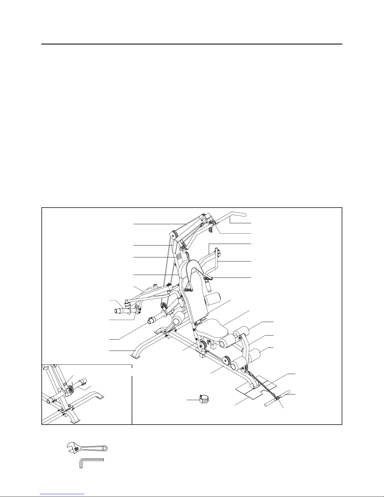
Lat Bar
Cable
Back Cushion
Foa m Roller
Leg Lift
Left Handlebar
Lever Arm
Foa m Roller
Ankle Cuff
Base Frame
Seat Cushion
Upright
Long Chain
THE FOLLOWING TOOLS ARE REQUIRED FOR ASSEMBLY :
Straight Bar
Handle
Left Leverage Arm
Lower Upright
BEFORE YOU BEGIN
Thank you for choosing the VG1500TM Leverage
System. W e take great pride in producing this quality
product and hope it will provide ma ny hours of quality
exercise to make you feel better , look better and enjoy
life to its fullest.
Yes, it's a proven fact that a regular exercise
program can improve your physical and mental
health. Too often, our busy lifestyles limit our time
and opportunity to exercise. The VG1500
TM
Leverage
System provides a convenient and simple method
to begin your assault on getting your body in shape
and achieving a happier and healthier lifestyle.
Before reading further, please review the drawing
below and fa mili arize yoursel f with the parts that are
labeled.
Read this manual carefully before using the
VG1500
TM
Leverage System.
Although Stamin a constructs its products with the
finest materials and uses the highest standards of
manufacturing and quality control, there can
sometimes be missing parts or incorrectly sized
parts. If you have any questions or problems with
the parts included with your VG1500
TM
Leverage
System, please do not return the product. Contact
us FIRST!
If a part is missing or defective, please call us toll
free at 1-800-375-7520 (in the U.S.). Our Customer
Service Staff is available to a ssist you from 7:30 A.M.
to 5:00 P .M. (Central T ime) Monday through Thursday
and 8:00 A.M. to 3:00 P.M. (Central Ti me) on Friday.
If you would like to contact us online, go to our
website at www.sta mina products.com a nd a ccess the
Customer Service section.
Be sure to have the name and model number of
the product available when you contact us.
Head Re st
Rear Stabilizer
Right Leverage Arm
Foot Plate
300 lbs Weight
Limit Notice Decal
( both sides )
Adjustable Wrench (two required, not included)
Allen Wrench (4mm) (two pieces included)
Lat Bar Warning La bel
Lever Arm
Right Weight Bar
400 lbs Weight Limit Notice Decal
Warning Label
Lat Bar Warning La bel
Ab Curl Strap
5
Part No. and Description Qty
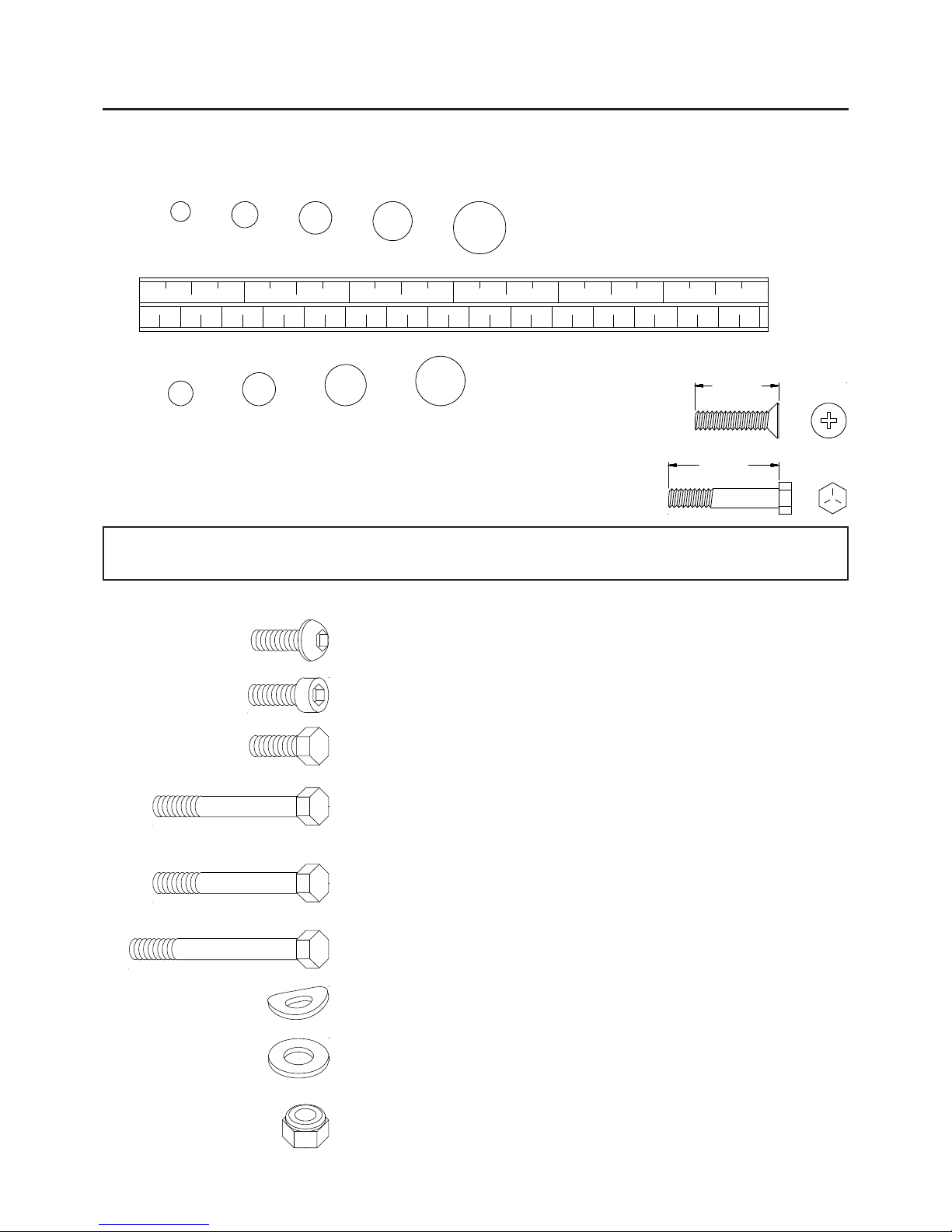
HARDWARE IDENTIFICATION CHART
This chart is provided to help identify the hardware used in the assembly process. Place the washers, the
end of the bolts, or screws on the circles to check for the corre ct diameter. Use the small scale to check the
length of the bolts and screws.
NOTICE: The length of all bolts and screws except those with flat hea ds is
measured from below the head to the end of the bolt or screw.
Flat head bolts and screws are measured from the top of the
head to the end of the bolt or screw.
mm.
in.
INCHES
MILLIMETERS
11/2021/2 31/2 41/2 51/2 61/2
0 10 20 30 40 50 60 70 80 90 100 110 120 130 140 150
6 8 10 12
3/16" 5/16" 1/2"3/8"1/4"
length
length
After unpacking the unit, open the hardware bag and make sure that you have all the following items.
Some hardware may be already attached to the part.
82 Nylock Nut (M12 x1.75) 25
83 Nylock Nut (M10 x1.5) 8
65 Bolt, Socket Head (M6 x 1 x 20mm) 2
64 Bolt, Button Head (M6 x 1 x 10mm) 2
67 Bolt, Hex Head (M10 x 1.5 x 25mm) 10
71 Bolt, Hex Head (M12 x 1.75 x 20mm) 6
68 Bolt, Hex Head (M10 x 1.5 x 50mm) 4
69 Bolt, Hex Head (M10 x 1.5 x 70mm) 1
70 Bolt, Hex Head (M10 x 1.5 x 95mm) 3
72 Bolt, Hex Head (M12 x 1.75 x 70mm) 5
73 Bolt, Hex Head (M12 x 1.75 x 80mm) 7
74 Bolt, Hex Head (M12 x 1.75 x 90mm) 2
75 Bolt, Hex Head (M12 x 1.75 x 100mm) 4
76 Bolt, Hex Head (M12 x 1.75 x 110mm) 2
77 Bolt, Hex Head (M12 x 1.75 x 160mm) 2
79 Large Washer (M12 x ø31mm) 4
80 Washer (M12 x ø25mm) 45
81 Washer (M10) 26
78 Arc Washer (M12) 4
ASSEMBLY INSTRUCTIONS
6
Place all parts from the box in a cleared area and position them on the floor in front of you. Remove all
packing materi als from your area a nd pla ce them ba ck into the box. Do not dispose of the pa cking materials
until assembly is completed. Read each step carefully before beginning. If you are missing a part please
call our toll-free number for assistance 1 (800) 375-7520 or e-mail us at: parts@staminaproducts.com
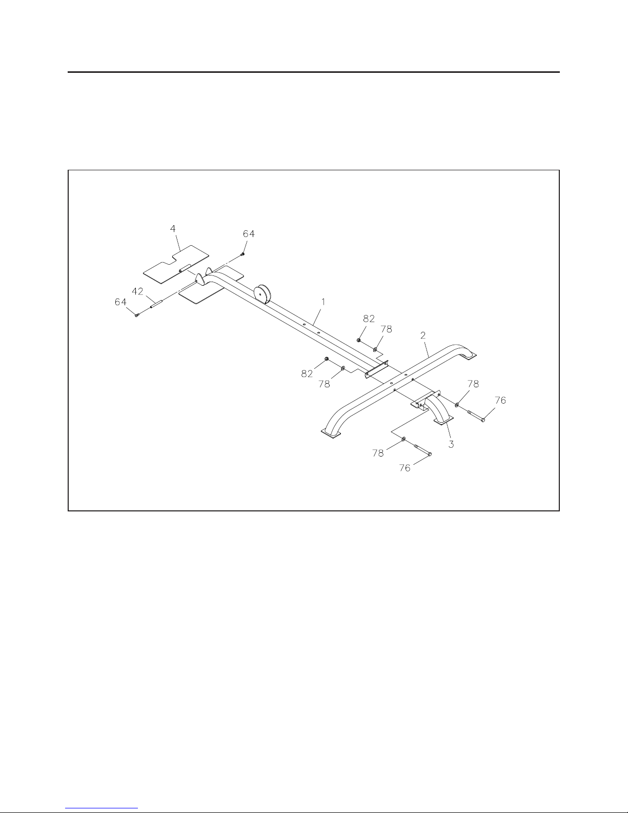
STEP 1
Attach the FOOT PLATE(4) to the BASE FRAME(1) with the SHAFT(42) an d BUTTON HEAD BOLTS
(M6x1x10mm)(64).
STEP 2
Refer to the illustration. Bolt the BASE FRAME(1), REAR ST ABILIZER(2), and REAR SUPPORT(3) together
with HEX BOL TS(M12x1.75x1 10mm)(76), ARC WASHERS(M12)(78), a nd NYLOCK NUTS(M12x1.75)(82).
Do not tighten the bolts until STEP 3.
FRONT
REAR
ASSEMBLY INSTRUCTIONS
7
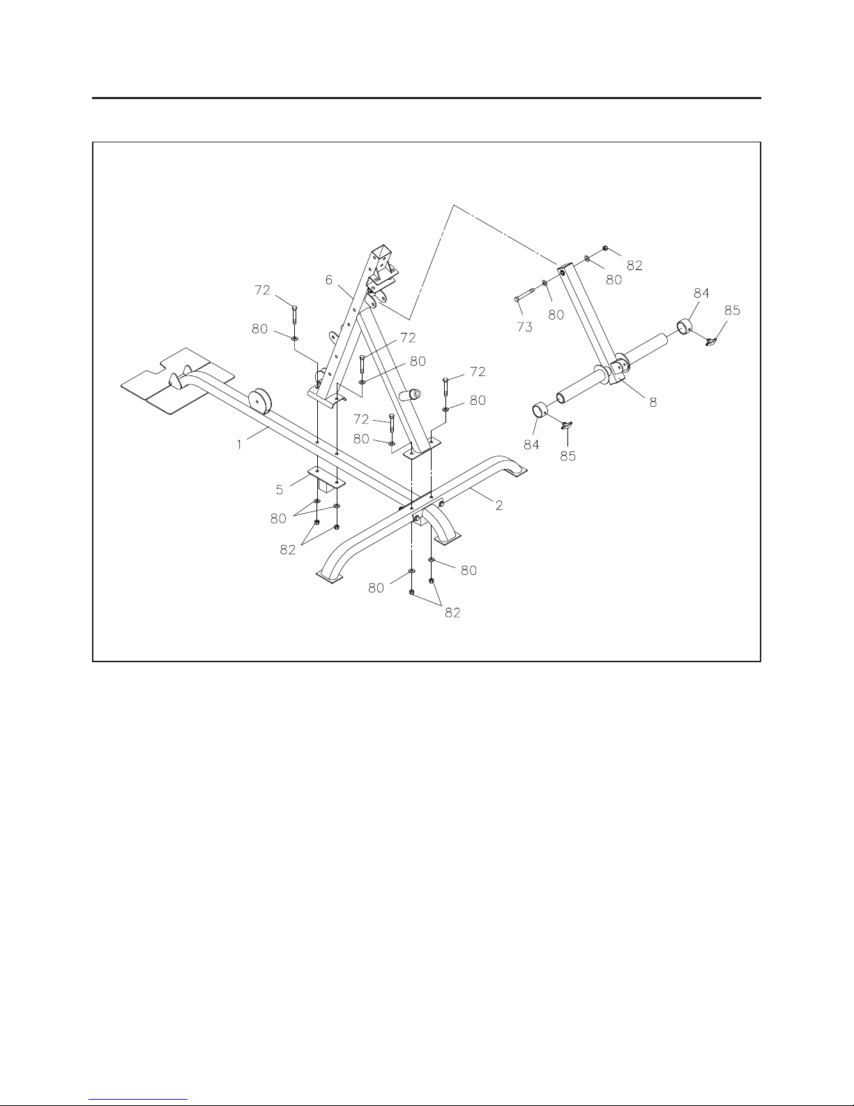
STEP 3
Attach the LOWER UPRIGHT(6) to the BASE FRAME(1) with the SUPPORT BRACKET(5), HEX BOLTS
(M12x1.75x70mm)(72), WASHERS(M12)(80), a nd NYLOCK NUTS(M12x1.75)(82). Do not tighten the bolts.
Attach the LOW UPRIGHT(6) to the REAR STABILIZER(2) with HEX BOLTS(M12x1.75x70mm)(72),
WASHERS(M12)(80), and NYLOCK NUTS(M12x1.75)(82). Tighten all bolts, including the bolts for
STEP 2.
STEP 4
Attach the LEVER ARM(8) to the LOWER UPRIGHT(6) with HEX BOLT(M12x1.75x80mm)(73), W ASHERS
(M12)(80), and NYLOCK NUT(M12x1.75)(82). Do not over tighten the bolt, as the LEVER ARM(8) must be
able to pivot smoothly.
STEP 5
Slide the WEIGHT COLLARS(84) onto both sides of the LEVER ARM(8) and lock in position with the
LOCKING KNOBS(85).
FRONT
REAR
 Loading...