

Page 1
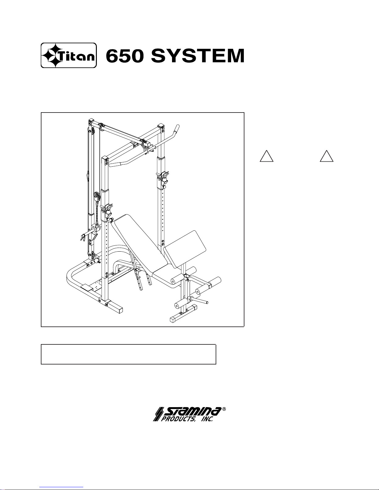
Owner's Manual
! WARNING !
Exercise can present a health
risk. Consult a physician
before beginning any exercise
program with this equipment.
If you feel faint or dizzy,
immediately discontinue use
of this equipment. Serious
bodily injury can occur if this
equipment is not assembled
and used correctly. Serious
bodily injury can also occur if
all instructions are not
followed. Keep others and
pets away from equipment
when in use. Always make
sure all bolts and nuts are
tightened prior to each use.
Follow all safety instructions in
this manual.
When calling for parts or
service, please specify the
following number.
50-0650A
STAMINA PRODUCTS
MADE IN CHINA
Product May Vary Slightly
From Pictured.
2000, 06
CAUTION: Weight on this product should not exceed
400 lbs, combined weight of user and barbell weight.
This Product is Produced Exclusively by
2757 S. Austin, Springfield, MO 65807
Customer Service Number
1 (800) 375-7520
www.staminaproducts.com
Page 2
TABLE OF CONTENTS
2
Before starting any exercise or conditioning program you should consult with your personal
physician to see if you require a complete physical exam. This is especially important if you
are over the age of 35, have never exercised before, are pregnant, or suffer from any
illness. READ AND FOLLOW THE SAFETY INSTRUCTIONS. FAILURE TO FOLLOW
THESE INSTRUCTIONS CAN RESUL T IN SERIOUS BODILY INJURY.
SAFETY INSTRUCTIONS
WARNING: To reduce the risk of serious injury, read the following Safety Instructions before
using the
.
WARNING:
Use the
only on a level surface.
Wear appropriate clothing when exercising; do not wear loose clothing that could become caught in
the
.
Keep small children and pets away from the
at all times including while using or
assembling the B
.
Combined weight of user and barbell weight not to exceed 400 lbs.
The
should be used by only one person at a time.
The FOOT PLATE must be used when performing exercises. Failure to use the FOOT PLATE could
result in the
tipping over and causing injury.
Be careful to maintain your balance while using, mounting, dismounting, or assembling the
, loss of balance may result in a fall and serious bodily injury.
Use the
only as described in the manual.
1.
2.
3.
4.
5.
6.
7.
8.
Page
Safety Instructions 2
Before You Begin 4
Hardware Illustrations 5
Assembly Instructions 6
Setting up The Accessories 12
Warm-up and Cool-Down 13
Stamina Fitness System (Workout Guide) 14
Product Parts Drawing 16
Parts List 17
Warranty 19
Note 20
Fax/Mail Ordering Form 22
Page 3
3
Should you have any questions, please call our Customer Service
Department toll-free number, 1 (800) 375-7520, Monday - Friday,
8:00 A.M. - 5:00 P.M., Central Time.
THANK YOU FOR PURCHASING THE
To help you get started, we have pre-assembled most of your
at the factory with the exception of those few parts left
unassembled for shipping purposes. Simply follow the few assembly
instructions set forth in this manual. Within a few minutes you will be getting
your body into shape and on your way to achieving a happier and healthier
lifestyle.
Page 4
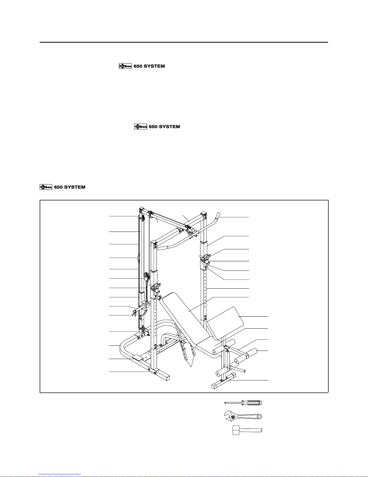
BEFORE YOU BEGIN
THE FOLLOWING TOOLS ARE REQUIRED FOR ASSEMBLY : Phillips Screwdriver
Adjustable Wrench
Rubber Mallet
Lat Bar
Weight Slider
U Shaped Pin
Bumper
Weight Support
Foot Plate
Base Frame
Spring Clip
Weight Bar
Main Upright Frame
Top Cable
Pulley
Weight Bar Slider
Chain
Single Pulley Brace
Bottom Cable
Chain Hook
Angle Adjust-
ment Tube
Side Upright Frame
Support Pin
Top
Beam
Cross Beam
Thank you f or choosing the
. We
take great pride in producing this quality product and
hope it will provide many hours of quality exercise
to make you feel better, look better and enjoy life to
its fullest.
Yes, it's a proven fact that a regular exercise
program can improve your physical and mental
health. Too often, our busy lifestyles limit our time
and opportunity to exercise. The
provides a convenient and simple method to begin
your assault on getting your body in shape and
achieving a happier and healthier lifestyle.
Before reading further, please review the drawing
below and familiarize yourself with the parts that are
labeled.
Read this manual carefully before using the
.
Although Stamina tries to manufacture its products
with the finest materials and uses the highest
standards of manufacturing, occasionally a part that
does not fit, is the incorrect size, or is otherwise
inappropriate is found. Even with the highest
inspection and quality controls in place these things
will happen occasionally. Please do not return the
product. For your convenience, Stamina has a
Customer Service Department with a toll-free
number. If a part is missing, does not fit, is the
incorrect size, or is otherwise inappropriate, please
call 1 (800) 375-7520 (in the U.S.) between 8:00 A.M.
and 5:00 P.M. Central T ime, Monday through Friday .
Our operators will be able to assist you with your
problem and the parts will be mailed directly to your
house.
4
Lower Main Upright
Lower Side Upright
Back Cushion
Leg Curl Frame
Foam Pad
Front Stabilizer
Seat Cushion
Arm Curl Cushion
Page 5
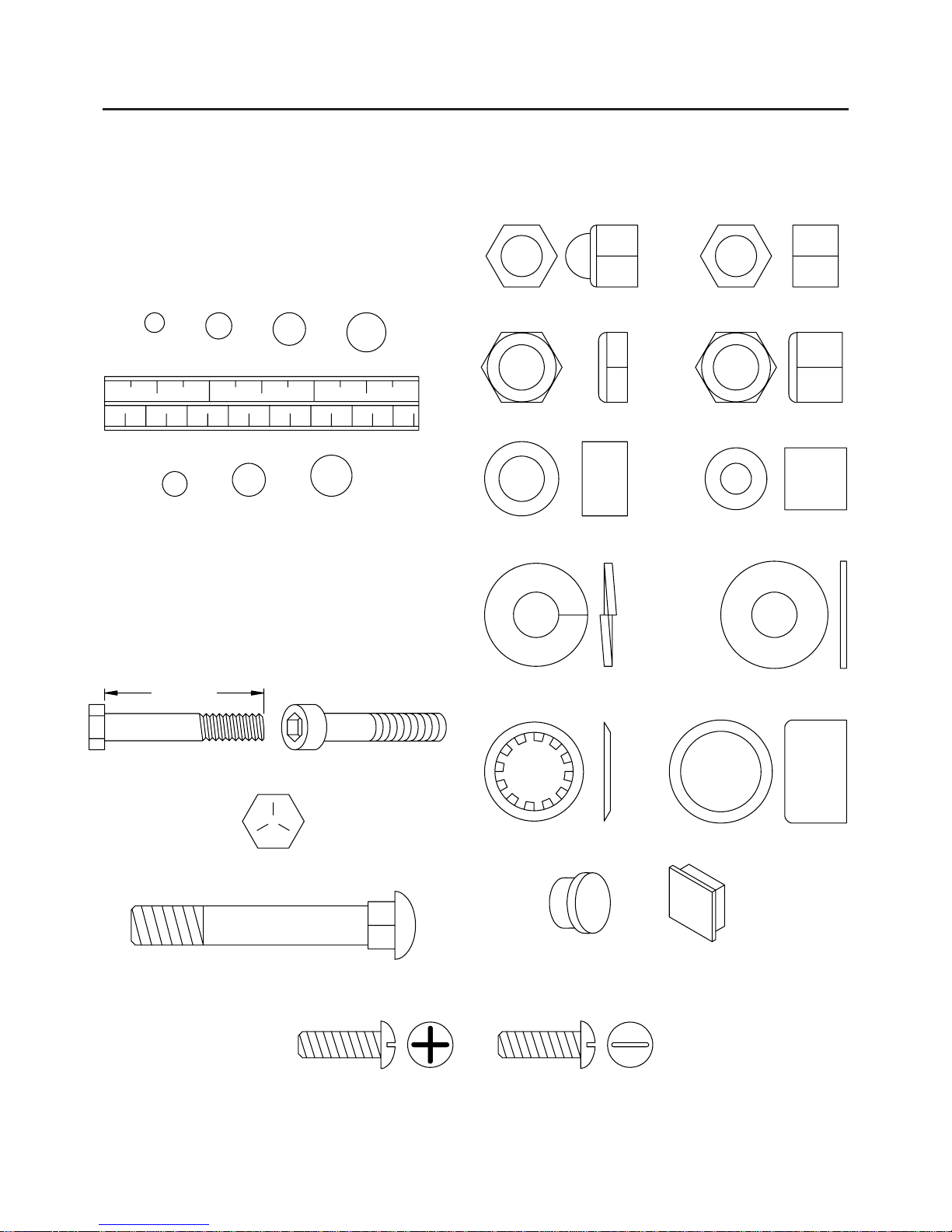
HARDWARE ILLUSTRATIONS
This chart is provided to help identify some of the small parts used in the assembly of this product. This
sheet may not include all the hardware needed to assemble your product. It is intended to be used as a
guide to help simplify your assembly process.
Bushing
Flat Washer
Retainer
Round
Plug
Square
Plug
Hex Head Bolt Top
Length
Hex Head Bolt Socket Head Screw
MILLIMETERS
INCHES
Place washers, the end of bolts or screws on
the circles to check for the correct size. Use
the small scale to check the sizes of bolts and
screws.
0 10 20 30 40 50 60 70
mm.
0 1/2 1 1/2
2 1/2 3
in.
3/16"
1/4" 5/16" 3/8"
6 8 10
Carriage Bolt
Phillips Head Screw Flat Head Screw
Acorn Nut Standard Nut
Thin Nylock Nut Nylock Nut
Spacer
Lock Washer
Retainer Cap
5
Page 6
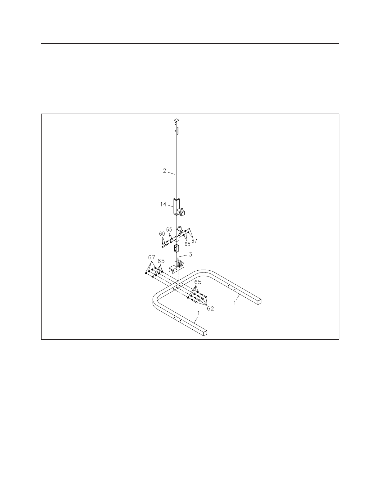
STEP 1
Attach the LOWER MAIN UPRIGHT(3) onto the two BASE FRAMES(1) with BOLTS(3/8" x 3")(62),
WASHERS(3/8")(65), and NYLOCK NUTS(3/8")(67).
STEP 2
Slide the WEIGHT BAR SLIDER(14) onto the MAIN UPRIGHT FRAME(2).
Attach the MAIN UPRIGHT FRAME(2) onto the LOWER MAIN UPRIGHT(3) with BOLTS
(3/8" x 2 1/8")(60), WASHERS(3/8")(65), and NYLOCK NUTS(3/8")(67).
ASSEMBLY INSTRUCTIONS
Place all parts from the box in a cleared area and position them on the floor in front of you. Remove all
packing materials from your area and place them back into the box. Do not dispose of the packing materials
until assembly is completed. Read each step carefully before beginning. If you are missing a part please
call our toll-free number for assistance 1 (800) 375-7520 or e-mail us at:
parts@staminaproducts.com
6
Page 7

ASSEMBLY INSTRUCTIONS
STEP 3
Attach the LOWER SIDE UPRIGHTS(7) onto both sides of the BASE FRAME(1) with BOLTS
(3/8" x 3")(62), WASHERS(3/8")(65), and NYLOCK NUTS(3/8")(67).
Slide the WEIGHT SUPPORTS(9) and WEIGHT SLIDERS(8) onto the two SIDE UPRIGHT
FRAMES(6), and lock in position with the SUPPORT PINS(11).
Attach the SIDE UPRIGHT FRAMES(6) onto both of the LOWER SIDE UPRIGHTS(7) with BOLTS
(3/8" x 2 1/2")(61), WASHERS(3/8")(65), and NYLOCK NUTS(3/8")(67).
NOTE: There are two U SHAPED PINS(12) to secure the BARBELL SET on WEIGHT SLIDERS(8).
STEP 4
Attach the CROSS BEAM(5) onto the tops of the two SIDE UPRIGHT FRAMES(6) with BOLTS
(3/8" x 3")(62), WASHERS(3/8")(65), and NYLOCK NUTS(3/8")(67).
Attach the T OP BEAM(4) onto the CROSS BEAM(5) with BOLTS(3/8" x 3")(62), WASHERS(3/8")
(65), and NYLOCK NUTS(3/8")(67). Atta ch the rear end of the TOP BEAM(4) onto the MAIN UPRIGHT
FRAME(2) with BOLTS(3/8" x 2 1/2")(61), WASHERS(3/8")(65), and NYLOCK NUTS(3/8")(67).
7
Page 8

ASSEMBLY INSTRUCTIONS
A
B
C
E
F
STEP 5
Run the EYELET END of the TOP CABLE(23), the longer one, through the slot at the front end of the
TOP BEAM(4). Attach the BALL END of the TOP CABLE(23) to the TOP BEAM(4) at A with a
PULLEY(20), a BOLT(3/8" x 2 1/8")(60), a NYLOCK NUT(3/8")(67), two WASHERS(3/8")(65),
and two PULLEY SPACERS(21). Use the same hardware to attach the TOP CABLE(23) to the TOP
BEAM(4) at B and to the MAIN UPRIGHT FRAME(2) at C.
Run the EYELET END of the BOTTOM CABLE(24), the shorter one, through the slot at the bottom end
of the
LOWER MAIN UPRIGHT(3). Atta ch the BALL END of the BOTTOM CABLE(24) to the LOWER
MAIN UPRIGHT(3) at D with a PULLEY(20), a BOLT(3/8" x 2 1/8")(60), a NYLOCK NUT(3/8")
(67), two WASHERS(3/8")(65), a nd two PULLEY SPACERS(21). Connect the EYELET END of the
BOTTOM CABLE(24) to the TOP CABLE(23) with the CHAIN HOOK(25) at E.
Attach the PULLEY BRACE(19) to the TOP CABLE(23) at F with the LAR GE PULLEY(22), a BOLT
(3/8" x 2 1/8")(60), a NYLOCK NUT(3/8")(67), and two WASHERS(3/8")(65). Connect the PULLEY
BRACE(19) to the WEIGHT BAR SLIDER(14) with a CHAIN(26) and two CHAIN HOOKS(25).
NOTE: Proper cable tension is achieved when the WEIGHT BAR SLIDER(14) is just touching the
BUMPER(13). Y ou ca n adjust the length of the CHAIN(26) between the PULLEY BRACE(19)
and the WEIGHT BAR SLIDER(14) to adjust the tension of the CABLES.
D
8
Page 9

STEP 6
Insert the WEIGHT BAR(16) through the hole on the WEIGHT BAR SLIDER(14). Slide the WEIGHT
BUMPERS(17) and SPRING CLIPS(18) onto both ends of the WEIGHT BAR(16).
STEP 7
Place the FOOT PLATE(31) onto the BASE FRAME(1).
NOTE: You can place the FOOT PLATE(31) in front of the SIDE UPRIGHT FRAME(5) for some squat
functions which allow you stand on the
FOOT PLATE(31) , or place the FOOT PLATE(31) in
rear of the
SIDE UPRIGHT FRAMES(6) for some bench functions which allow you to put the
bench on the
FOOT PLATE(31), as shown in inset drawing.
The
FOOT PLATE(31) must be used when performing exercises. Failure to use the
FOOT PLATE(31) could result in the tipping over and causing injury.
STEP 8
Place the BARBELL SET onto the WEIGHT SLIDERS(8). You can lock the BARBELL SET and
WEIGHT SLIDERS(8) together with two U SHAPED PINS(12) for some squat functions or bench press
functions, as shown in inset drawing.
The BARBELL SET is not included with this unit.
ASSEMBLY INSTRUCTIONS
BENCH
Barbell Set not
include with unit.
BARBELL
SET
9
CAUTION:
Page 10

ASSEMBLY INSTRUCTIONS
STEP 9
Attach the FRONT ST ABILIZER(34) a nd the REAR ST ABLIZER(35) onto the BENCH MAIN FRAME
(33) with BOLTS(M8 x 15mm)(57) and WASHERS(M8)(64).
NOTE: The REAR STABILIZER(35) is longer than the FRONT STABILIZER(34).
STEP 10
Press the ROUND ANGLE CAP(40) onto the back side of the LEG CURL FRAME(36). Attach the
LEG CURL FRAME(36) onto the BENCH MAIN FRAME(33) with BOLT(3/8" x 2 1/2")(61),
WASHERS(3/8")(65), and NYLOCK NUT(3/8")(67).
NOTE: Please make sure the angle of the ROUND ANGLE CAP(40) matches with the BENCH MAIN
FRAME(33).
STEP 11
Slide the FOAM PAD(38) onto the PAD TUBE(37), then insert the other end of the PAD TUBE(37)
through the hole on the BENCH MAIN FRAME(33). Slide another FOAM PAD(38) over the protruding
end of the
PAD TUBE(37). Repeat for the LEG CURL FRAME (36). Slide the WEIGHT STOP(39)
onto the WEIGHT TUBE on the LEG CURL FRAME(36).
WEIGHT TUBE
10
Page 11

ASSEMBLY INSTRUCTIONS
11
STEP 12
Attach the BACK CUSHION BRACE FRAME(43) onto the BENCH MAIN FRAME(33) with BOLT
(3/8" x 4 5/8")(63), WASHERS(3/8")(65), and NYLOCK NUT(3/8")(67).
STEP 13
NOTE: ANGLE ADJUSTMENT TUBES(44) and ANGLE ADJUSTMENT BRACES(45) must be
assembled as shown above.
Attach the two
ANGLE ADJUSTMENT TUBES(44) onto both sides of the BACK CUSHION BRACE
FRAME(43) with BOL T(M8 x 165mm)(58), W ASHERS(M8)(64), and NYLOCK NUT(M8)(66). Slide
the two
ANGLE ADJUSTMENT BRACES(45) onto the ANGLE ADJUSTMENT TUBES(44), then
attach to the
BENCH MAIN FRAME(33) with BOLT(M8 x 165mm)(58), SHAFT TUBE(46),
WASHERS(M8)(64), a nd NYLOCK NUT(M8)(66). Lock the BACK CUSHION BRACE FRAME(43)
in position with the LOCKING PIN(47).
NOTE: To achieve incline / decline a ngles of the BACK CUSHION ASSEMBLY, insert the LOCKING
PIN(47) in the desired holes of the ANGLE ADJUSTMENT TUBES(44).
STEP 14
Attach the SEAT CUSHION(41) onto the BENCH MAIN FRAME(33) with BOLTS (M8 x 15mm)(57)
and WASHERS(M8)(64). Attach the BACK CUSHION(42) onto the BACK CUSHION BRACE
FRAME(43) with BOLTS(M8 x 15mm)(57) and WASHERS(M8)(64).
Page 12

SETTING UP THE ACCESSORIES
LA T BAR(28)
Attach the LAT BAR(28) onto the TOP CABLE(23) with a CHAIN HOOK(25).
For some exercises, the CHAIN(26) should be attached between the LA T BAR(28) a nd the TOP CABLE
(23) with two CHAIN HOOKS(25).
CURL BAR(29), ANKLE STRAP(30)
The above acce ssories ca n be attached to the BALL END of the BOTTOM CABLE(24) at the bottom of
the
LOWER MAIN UPRIGHT(3) with two CHAIN HOOKS(25) and a CHAIN(26).
NOTE: Adjust the length of the CHAIN(26) between the ACCESSORY and the CABLE. Have the
ACCESSORY in the correct starting position for exercise to be performed.
ARM CURL CUSHION(54)
Attach the ARM CURL CUSHION(54) onto the ARM CURL POST(55) with BOLTS(M6 x 14mm)
(56). Insert the ARM CURL POST(55) into the front of the BENCH MAIN FRAME(33) and lock in
position with
SUPPORT PIN(11).
NOTE: There are three adjustment holes on the ARM CURL POST(55) for adjusting the height of the
ARM CURL CUSHION(54).
12
Page 13

WARM-UP and COOL-DOWN
Warm-up The purpose of warming up is to pre pare your body f or exercise and to minimize injuries. Warm
up for two to five minutes before strength-training or aerobic exercising. Perform activities that raise your
heart rate and warm the working muscles. Activities may include brisk walking, jogging, jumping jacks,
jump rope, and running in place
Stretching Stretching while your muscles are warm after a proper warm-up and again after your strength
or aerobic training session is very important. Muscles stretch more easily at these times because of their
elevated temperature, which greatly reduces the risk of injury. Stretches should be held for 15 to 30
seconds. Do not bounce.
Suggested Stretching Exercises
Lower Body Stretch
Place feet shoulder-width
apart and lean forward.
Keep this position for 30
seconds using the body as a
natural weight to stretch the
backs of the legs. DO NOT
BOUNCE!
When the pull on the back of
the legs lessen, try a lower
position gradually.
Floor Stretch
While sitting on the floor,
open the legs as wide as
possible. Stretch the upper
body toward the knee on the
right leg by using your arms
to pull your chest to your
thighs. Hold this stretch 10
to 30 seconds. DO NOT
BOUNCE! Do this stretch
10 times. Repeat the stretch
with the left leg.
Bent Over Leg Stretch
Stand with feet shoulderwidth apart and lean forward
as illustrated. Using the
arms,
gently pull the upper
body towards the right leg.
Let the head hang down.
DO NOT BOUNCE! Hold the
position a minimum of 10
seconds. Repeat pulling the
upper body to the left leg.
Do this stretch several times
slowly.
Remember always to check with your physician before starting any exercise program.
Cool-Down The purpose of cooling down is to return the body to its normal, or near normal, resting state
at the end of each exercise session. A proper cool-down slowly lowers your heart rate and allows blood to
return to the heart. Your cool-down should include the stretches listed above and should be completed
after each strength-training session.
Bent Torso Pulls
While sitting on the floor,
have legs apart one leg
straight and one knee bent.
Pull the chest down to touch
the thigh on the leg that is
bent and twist at the waist.
Hold this position at least 10
seconds. Repeat 10 times
on each side.
13
Page 14

14
Page 15

15
Page 16

PRODUCT PARTS DRAWING
16
BACK
FRONT
Page 17

PARTS LIST
DIAGRAM# PART NAME QTY
1 Base Frame 2
2 Main Upright Frame 1
3 Lower Main Upright 1
4 Top Beam 1
5 Cross Beam 1
6 Side Upright Frame 2
7 Lower Side Upright 2
8 Weight Slider 2
9 Weight Support 2
10 Weight Bushing 8
11 Support Pin 3
12 U Shaped Pin 2
13 Bumper 3
14 Weight Bar Slider 1
15 Weight Bar Bushing 2
16 Weight Bar 1
17 Weight Bumper 2
18 Spring Clip 2
19 Pulley Brace 1
20 Pulley (od. 85mm) 4
21 Pulley Spacer 8
22 Large Pulley (od. 90mm) 1
23 Top Cable (3200mm or 126") 1
24 Bottom Cable (1450mm or 57") 1
25 Chain Hook 5
26 Chain 2
27 Hand Grip 4
28 Lat Bar 1
29 Curl Bar 1
30 Ankle Strap 1
31 Foot Plate 1
32 Foot Plate Tape 1
33 Bench Main Frame 1
34 Front Stabilizer 1
35 Rear Stabilizer 1
36 Leg Curl Frame 1
37 Pad Tube 3
38 Foam Pad 6
39 Weight Stop 1
40 Round Angle Cap 1
41 Seat Cushion 1
42 Back Cushion 1
43 Back Cushion Brace Frame 1
44 Angle Adjustment Tube 2
45 Angle Adjustment Brace 2
17
Page 18

46 Shaft Tube 1
47 Locking Pin 1
48 End Cap (38mm x 38mm) 4
49 Square Plug (20mm) 8
50 Square Plug (38mm) 4
51 Square Plug (50mm) 4
52 Round Plug (25mm) 3
53 Round Plug (19mm) 6
54 Arm Curl Cushion 1
55 Arm Curl Post 1
56 Bolt, Round Head (M6 x 1 x 14mm) 2
57 Bolt, Hex Head (M8 x 1.25 x 15mm) 12
58 Bolt, Hex Head (M8 x 1.25 x 165mm) 2
59 Bolt, Hex Head (3/8" - 16 x 1") 3
60 Bolt, Hex Head (3/8" - 16 x 2 1/8") 7
61 Bolt, Hex Head (3/8" - 16 x 2 1/2") 7
62 Bolt, Hex Head (3/8" - 16 x 3") 14
63 Bolt, Hex Head (3/8" - 16 x 4 5/8") 1
64 Washer (M8) 16
65 Washer (3/8") 58
66 Nylock Nut (M8 x 1.25) 2
67 Nylock Nut (3/8" - 16) 29
68 Manual 1
PARTS LIST
DIAGRAM# PART NAME QTY
18
Page 19

Sta min a Products, Inc. (the "Warrantor") warrants to the original purchaser only, that this product will be free
from defects in materials and workmanship under normal use, service and proper operation for a period of 90
days on the parts and 5 years on the frame from the date of the purchase by the original purchaser.
THIS WARRANTY SHALL NOT APPLY TO ANY PRODUCT WHICH HAS BEEN SUBJECT TO
COMMERCIAL USE, ABUSE, MISUSE, ALTERATION OF ANY TYPE OR CAUSE OR TO ANY DEFECT
OR DAMAGE CAUSED BY REPAIR, REPLACEMENT, SUBSTITUTION OR USE WITH PARTS OTHER
THAN P ARTS PROVIDED BY STAMINA PRODUCTS, INC. Commercial use include s use of the product in
athletic clubs, health clubs, spas, gymnasiums, exercise facilities, and other public or semipublic facilities
whether or not the product's use is in furtherance of a profit making enterprise, and all other use which is not
for personal, family, or household purposes.
To implement this limited warranty , send a written notice stating your name, date, and place of purcha se and
a brief description of the defect along with your re ceipt to Sta mina Products, Inc. P.O. Box 1071, Springfield
Missouri, USA, 65801-1071 or call us at 1 (800) 375-7520. If the defect is covered under this limited
warranty, you will be requested to return the product or part to us for free repair or repla cement at our option.
NO ACTION FOR BREACH OF THIS LIMITED W ARRANTY MA Y BE COMMENCED MORE THAN ONE (1)
YEAR AFTER THE DATE THE ALLEGED BREACH WAS OR SHOULD HAVE BEEN DISCOVERED. NO
ACTION FOR BREACH OF ANY IMPLIED WARRANTY MAY BE COMMENCED MORE THAN ONE (1)
YEAR AFTER DELIVERY OF THE PRODUCT TO THE PURCHASER. This limited warranty is not
transferable. IF ANY PART OF THE PRODUCT IS NOT IN COMPLIANCE WITH THIS LIMITED W ARRANTY
OR ANY IMPLIED WARRANTY, THE REMEDY OF REPAIR OR REPLACEMENT IS THE EXCLUSIVE
REMEDY A V AILABLE TO YOU. In the event that the purcha ser ma ke s a ny claim under this li mited warra nty
or any i mplied warranty, the W arrantor reserves the right to require the product to be returned for inspection,
at the purchaser's expense, to the Warrantor's premises in Springfield, Missouri. Return of the enclosed
warranty registration card is not required for warranty coverage, but is merely a way of establishing the date
and place of purchase.
Stamina Products, Inc. SHALL NOT BE LIABLE FOR THE LOSS OF USE OF ANY PRODUCT, LOSS OF
TIME, INCON VENIENCE, COMMERCIAL LOSS OR ANY OTHER INDIRECT , CONSEQUENTIAL, SPECIAL
OR INCIDENTAL DAMAGES DUE TO BREACH OF THE ABOVE WARRANTY OR ANY IMPLIED
WARRANTY.
This limited warranty is the only written or express warranty given by Stamina Products, Inc. This warranty
gives you specific legal rights, and you may also have other legal rights which vary from state to state.
ANY OTHER RIGHT WHICH YOU MAY HAVE, INCLUDING ANY IMPLIED WARRANTY OR
MERCHANTABILITY OR FITNESS FOR A PARTICULAR PURPOSE, IS LIMITED IN DURATION TO THE
DURA TION OF THIS WARRANTY .
The laws in some jurisdictions restrict the rights of manufacturers and distributors of consumer goods to
disclaim or limit implied warranties and consequential and incidental damages with respect thereto. If any
such law is found to be applicable, the foregoing disclaimers and limitations of and on implied warranties and
consequential and incidental damages with respect thereto shall be disregarded and shall be deemed not to
have been made to the extent necessary to comply with such legal restriction.
LIMITED WARRANTY
MODEL 50-0650A
W ARRANTY
19
Page 20

NOTES
20
Page 21

NOTES
21
Page 22

Phone #: ( ) Work Phone #: ( )
Date Purchased:
Model #:
Purchased From:
Mr./Ms.:
Address: Apt. #:
City: state: Zip Code:
IMPORT ANT: We must have your phone number in order to proce ss the order!
Stamina Products, Inc.
P.O. Box 1071
Springfield, MO 65801-1071
IMPORT ANT: Before filling out the form below make sure you have the right information. Refer
to the parts list to make sure you're ordering the right parts!
PART # DESCRIPTION QUANTITY
1 Rear Unit Assembly 1
EXAMPLE:
Detach and Mail or Fax the Form Below
TELEPHONE
CUSTOMER SERVICE
Tel: 1 (800) 375-7520
FAX
CUSTOMER SERVICE
Fax: (417) 889-8064
MAIL
STAMINA PRODUCTS, INC.
ATTN: Customer Service
P.O. Box 1071
Springfield, MO. 65801-1071
FAX/MAIL ORDERING FORM
ONLINE
CUSTOMER SERVICE
parts@staminaproducts.com
www.staminaproducts.com
Please do not return the product. For your convenience, Stamina has a Customer Service
Department with a toll-free number. Should a part be missing or a defective part found, please call
1 (800) 375-7520 (in the U.S.) between 8:00 A.M. and 5:00 P.M. Central T ime, Monday through Friday
or fill out the fax sheet ordering form below and fax it to (417) 889-8064. Our Customer Service
Department will be able to assist you with your problem and the part will be mailed directly to your
house.
 Loading...