

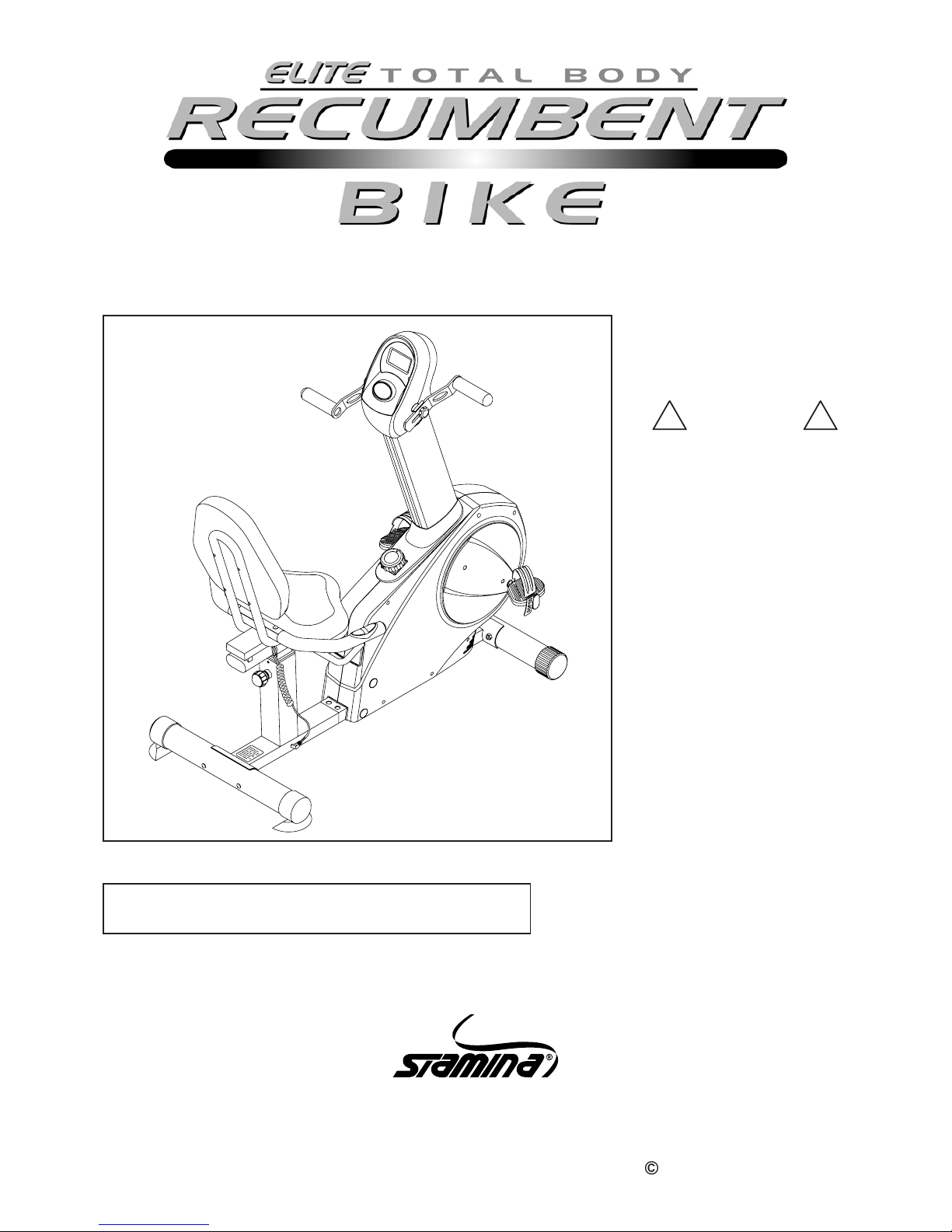
Stamina Elite Total Body, 15-9100 Owner's Manual
2005, 05
This Product is Produced Exclusively by
2040 N. Alliance, Springfield, MO 65803
Customer Service Number
1 (800) 375-7520
www.staminaproducts.com
15-9100
STAMINA PRODUCTS
MADE IN TAIWAN
Product May Vary Slightly
From Pictured.
CAUTION:
We ight on this product should not exceed 250 lbs.
! WARNING !
Exercise can present a he alth
risk. Consult a physician
before beginning any exercise
program with this equipment.
If you feel faint or dizzy,
immediately discontinue use
of this equipment. Serious
bodily injury can occur if this
equipment is not assembled
and used correctly. Serious
bodily injury can also occur if
all instructions are not
followed. Keep others and
pets away from equipment
when in use. Always make
sure all bolts and nuts are
tightened prior to each use.
Follow all safety instructions in
this manual.
When calling for parts or
service, please specify the
following number.
Owner's Manual
2005 Stamina Products, Inc.

TABLE OF CONTENTS
Before starting any exercise or conditioning program you should consult with your personal
physicia n to see if you require a complete physical exam. This is especially importa nt if you
are over the age of 35, have never exercised before, are pregnant, or suffer from any
illness. READ AND FOLLOW THE SAFETY PRECAUTIONS. FAILURE TO FOLLOW
THESE INSTRUCTIONS CAN RESUL T IN SERIOUS BODILY INJURY.
WARNING:
2
SAFETY INSTRUCTIONS
WARNING:
Safety Instructions 2
Before Y ou Begin 4
Hardware Identification Chart 5
Assembly Instructions 6
Using The Electronic Meter 10
Set Up Instructions 11
Operational Instructions 12
Storage 13
Maintenance 13
Conditioning Guidelines 14
Warm-up a nd Cool-Down 15
Product Parts Drawing 16
Parts List 17
Warranty 19
Notes 20
Fax/Mail Ordering Form 22
Page Page
Read all warnings posted on the TOTAL BODY RECUMBENT BIKE.
The TOT AL BODY RECUMBENT BIKE should only be used after a thorough review of the Owner's
Manual.
We recommend that two people be available for assembly of this product.
Keep children away from the TOT AL BODY RECUMBENT BIKE. Do not allow children to use or play on
the TOTAL BODY RECUMBENT BIKE. Keep children and pets away from the TOTAL BODY
RECUMBENT BIKE when it is in use.
Make sure that the T OTAL BODY RECUMBENT BIKE is properly a ssembled a nd tightened before
use.
It is recommended that you place this exercise equipment on an equipment mat.
Set up and operate the TO T AL BODY RECUMBENT BIKE on a solid level surfa ce. Do not position
the TOTAL BODY RECUMBENT BIKE on loose rugs or uneven surfaces.
Adjust the STAND(65) under the REAR FRAME(2) to get more support for the base of the TOTAL
BODY RECUMBENT BIKE.
Inspect the TOTAL BODY RECUMBENT BIKE worn or loose components prior to use. Tighten/
replace any loose or worn components prior to using.
The ADJUSTMENT K NOBS(52) a nd SPRING K NOB(64) should be securely tightened prior to use.
Each user should adjust the seat per instructions on page 12.
Do not attempt to adjust the seat while you are on the TOTAL BODY RECUMBENT BIKE.
Consult a physician prior to commencing an exercise program. If, at any time during exercise, you
feel faint, dizzy, or experience pain, stop and consult your physician.
Follow your physician's recommendations in developing your own personal fitness program.
Always choose the workout which best fits your physical strength and flexibility level. Know your
limits and train within them. Always use common sense when exercising.
Do not wear loose or dangling clothing while using the TOTAL BODY RECUMBENT BIKE.
Never exercise in bare feet or socks; always wear correct footwear, such as running, walking, or
crosstraining shoes. Be sure that they fit well, provide foot support a nd feature non-s kid rubber soles.
Care should be taken in mounting or dismounting the TO TAL BODY RECUMBENT BIKE.
The TOTAL BODY RECUMBENT BIKE should not be used by persons weighing over 250 pounds.
The TOTAL BODY RECUMBENT BIKE should be used by only one person at a time.
The TOT AL BODY RECUMBENT BIKE is for consumer use only . It is not for use in public or semi public
facilities.
1.
2.
3.
4.
5.
6.
7.
8.
9.
10.
11.
12.
13.
14.
15.
16.
17.
18.
19.
20.
21.
To reduce the risk of serious injury, read the following Safety Instructions before
using th
e TOTAL BODY RECUMBENT BIKE.

3
CALL US FIRSTCALL US FIRST
CALL US FIRSTCALL US FIRST
CALL US FIRST
THANK YOU FOR PURCHASING THE
TOTAL BODY RECUMBENT BIKE
To help you get started, we have pre-assembled most of your
TOTAL BODY RECUMBENT BIKE at the factory with the exception
of those few parts left unassembled for shipping purposes.
Simply follow the few assembly instructions set forth in this manual.
Within a few minutes you will be getting your body into shape and on your
way to achieving a happier and healthier lifestyle.
Should you have any que stions,
please call our Customer Service Department toll-free number,
1 (800) 375-7520
Monday - Friday, 8:00 A.M. - 5:00 P.M., Central Time.
BEFORE YOU BEGIN
Thank you for choosing the TOTAL BODY
RECUMBENT BIKE. We take great pride in
producing this quality product and hope it will provide
many hours of quality exercise to make you feel
better, look better and enjoy life to its fullest.
Yes, it's a proven fact that a regular exercise
program can improve your physical and mental
health. Too often, our busy lifestyles limit our time
and opportunity to exercise. The
TOTAL BODY
RECUMBENT BIKE provides a convenient and
simple method to begin your assault on getting your
body in sha pe a nd a chieving a happier and healthier
lifestyle.
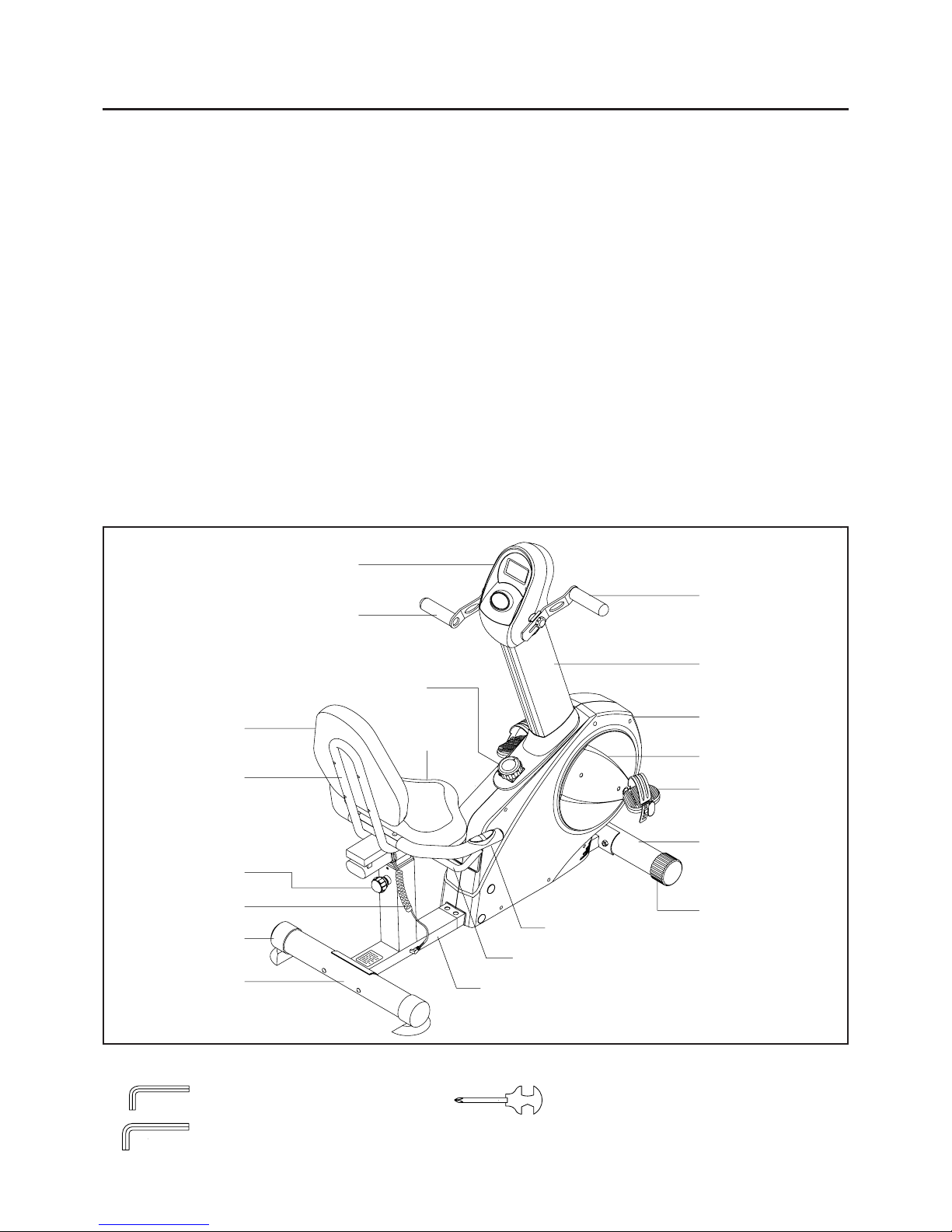
Before reading further, please review the drawing
below and familiarize yourself with the parts that are
labeled.
Read this ma nual carefully before using the
TOTAL
BODY RECUMBENT BIKE.
Although Stamina tries to manufa cture its products
with the finest materials and uses the highest
standards of ma nufacturing, occasionally a part that
does not fit, is the incorrect size, or is otherwise
inappropriate is found. Even with the highest
inspection and quality controls in place these things
will happen occasionally. Please do not return the
product. For your convenience, Stamina has a
Customer Service Department with a toll-free
number. If a part is missing, does not fit, is the
incorrect size, or is otherwise inappropriate, please
call 1 (800) 375-7520 (in the U.S.) between 8:00 A.M.
and 5:00 P.M. Central Ti me, Monday through Friday .
Our operators will be able to assist you with your
problem and the parts will be mailed directly to your
house.
4
Seat Adjustment Lever
Rear Frame
Front Stabilizer
Right AL Upright
Right Cover
Crank Cover
Endcap
Right Pedal
Handrail
Spring Knob
Handlebar
Meter
Tension Knob
Seat
Seat Frame
Back Cushion
Stand Ca p
Pulse Sensor
Wire
Rear Stabilizer
Handlebar
THE FOLLOWING TOOLS ARE INCLUDED FOR ASSEMBLY :
Allen Wrench (4mm)
Allen Wrench (6mm)
Combination Wrench (13mm a nd 15mm)
5
Part No. and Description Qty
mm.
in.
INCHES
MILLIMETERS
11/2021/2 31/2 41/2 51/2 61/2
0 10 20 30 40 50 60 70 80 90 100 110 120 130 140 150
6 8 10 12
3/16" 5/16" 1/2"3/8"1/4"
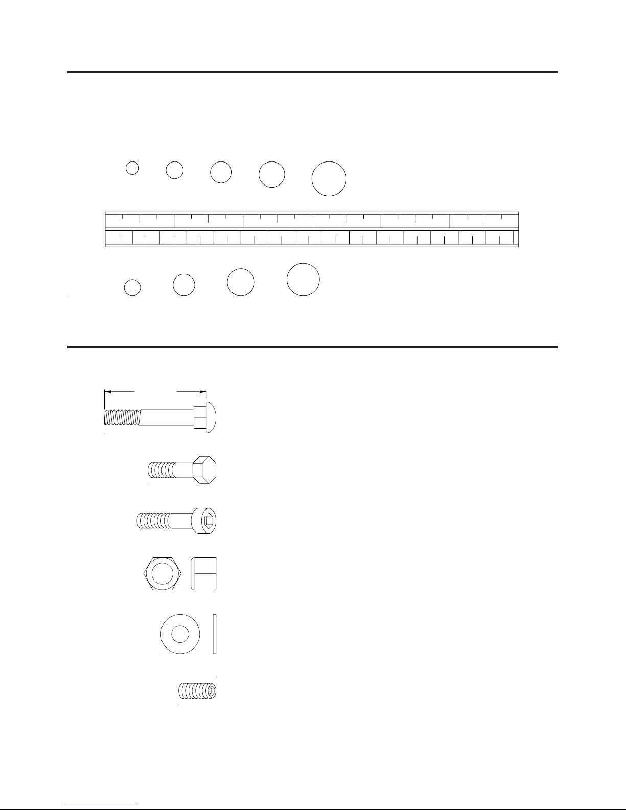
HARDWARE IDENTIFICATION CHART
Place washers, the end of bolts or screws on the
circles to check for the correct size. Use the small
scale to check the sizes of bolts and screws.
This chart is provided to help identify the hardware used in the a ssembly process. After unpacking the unit,
open the hardware bag and make sure that you have the following items:
NOTE: Some of the hardware items listed may be attached to other parts.
74 Washer (M8) 2
79 Carriage Bolt (M8 x 1.25 x 85mm) 4
99 Carriage Bolt (M8 x 1.25 x 50mm) 2
80 Nylock Nut (M8 x 1.25) 10
85 Bolt, Scoket Head (M8 x 1.25 x 50mm) 3
96 Bolt, Hex Head (M8 x 1.25 x 40mm) 4
97 Bolt, Hex Head (M8 x 1.25 x 15mm) 4
Length
98 Set Screw (M6 x 1 x 15mm) 2
ASSEMBLY INSTRUCTIONS
Place all parts from the box in a cleared area and position them on the floor in front of you. Remove all
packing materi als from your area a nd pla ce them ba ck into the box. Do not dispose of the pa cking materials
until assembly is completed. Read each step carefully before beginning. If you are missing a part please
call our toll-free number for assistance 1 (800) 375-7520 or e-mail us at: parts@staminaproducts.com
6
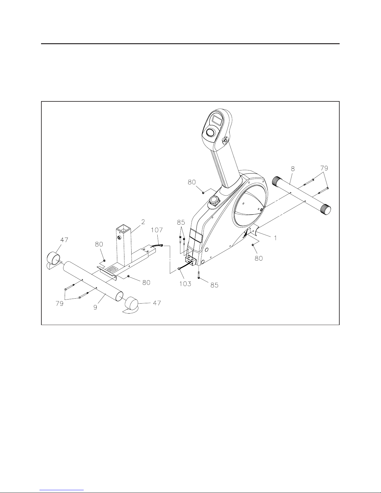
STEP 1
Attach the FRONT ST ABILIZER(8) onto the MAIN FRAME(1) with CARRIAGE BOL TS(M8 x 85mm)
(79) and NYLOCK NUTS(M8)(80).
STEP 2
Connect the PULSE EXTENSION WIRE(107) to the PULSE CONNECTION WIRE(103). Insert the
REAR FRAME(2) into the MAIN FRAME(1) and secure with SOCKET HEAD BOLTS(M8 x 50mm)
(85).
STEP 3
Attach the REAR ST ABILIZER(9) onto the REAR FRAME(2) with CARRIAGE BOL TS(M8 x 85mm)
(79) and NYLOCK NUTS(M8)(80). Press the STAND CAPS(47) onto both sides of the REAR
STABILIZER(9).
ASSEMBLY INSTRUCTIONS
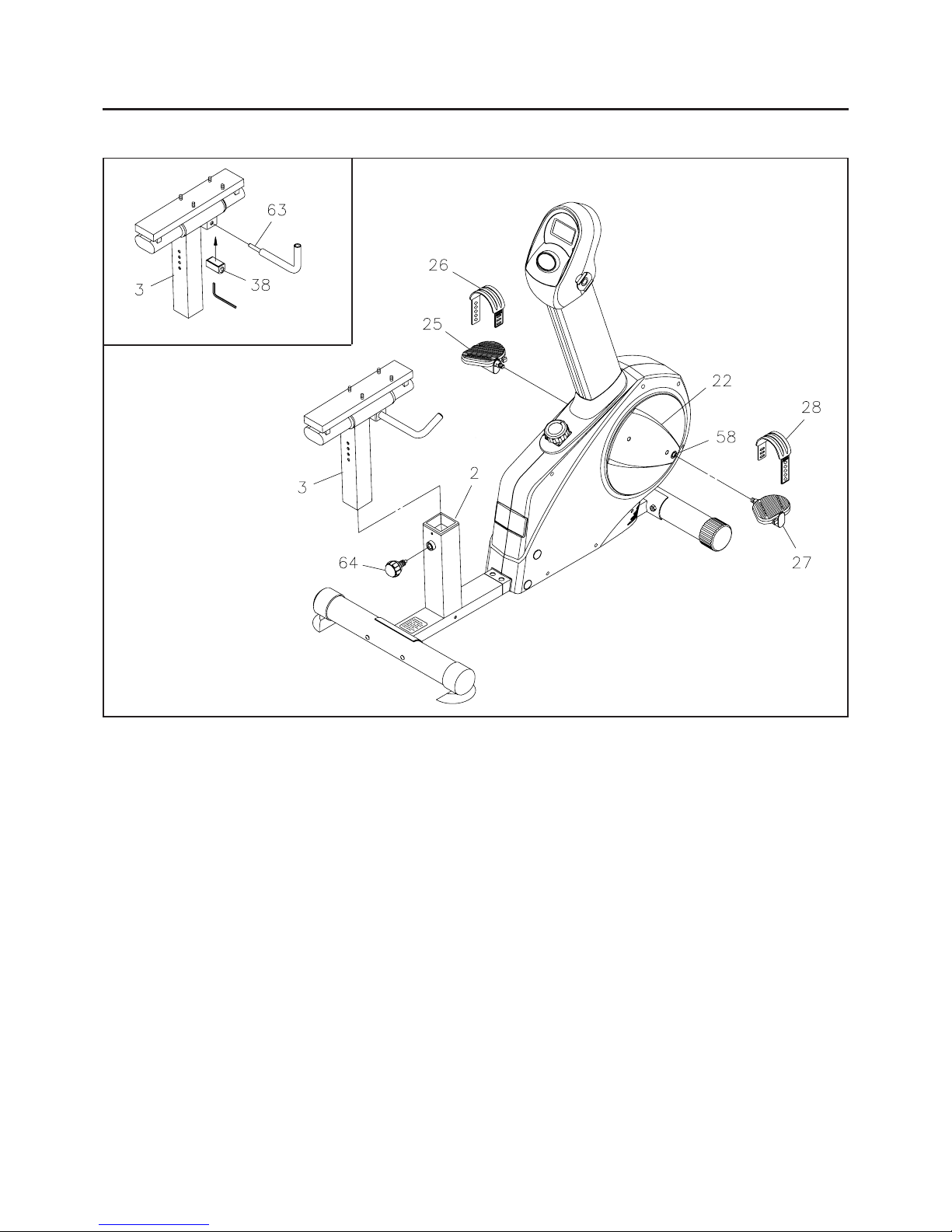
7
Allen Wrench
STEP 4
NOTE:
Thread the
RIGHT PEDAL(27) onto the RIGHT CRANK(58) located inside the CRANK COVER(22)
as shown. Tighten the pedal securely. Select the RIGHT PEDAL STRAP(28) which has R marked on
the bottom side of the strap. Snap the three hole end onto the inside edge of the
RIGHT PEDAL(27).
Sna p the other end onto the outside edge of the RIGHT PEDAL(27) with the R mark on the bottom of the
RIGHT PEDAL STRAP(28). Select adjustment holes which allow your foot to be easily removed from
the pedals. Use the same procedure to attach the
LEFT PEDAL(25) onto the LEFT CRANK(57) and
snap the
LEFT PEDAL STRAP(26) onto the LEFT PEDAL(25).
The RIGHT PEDAL(27) ha s R stamped on the end of the pedal shaft. The RIGHT PEDAL(27)
ha s right hand threa ds and is tightened by turning clockwise. The LEFT PEDAL(25) ha s L stamped
on the end of the pedal shaft. The
LEFT PEDAL(25) has left hand threads and is tightened by
turning counter clockwise.
STEP 6: Insert the SEA T POST(3) into the REAR FRAME(2) and se cure with the SPRING KNOB(64).
NOTE:
The
SPRING KNOB(64) should be screwed in tight to make the SEAT POST(3) fit securely in
the
REAR FRAME(2).
STEP 5: Refer to the inset drawing. Insert the ADJUSTMENT BLOCK(38) into the SEAT POST(3).
Insert the SEAT ADJUSTMENT LEVER(63) through the SEAT POST(3) and ADJUSTMENT
BLOCK(38) and secure by tightening the set screws inside the ADJUSTMENT BLOCK(38) with Allen
Wrench.
 Loading...