

Stabila Tech 500 DP User Manual

TECH 500 DP
How true pro’s measure
User manual

TECH 500 DP
en
Contents
Section Page
• 1 Intended use 3
• 2 Safety information 3
• 3. Components of the unit 4
• 4. Display elements 5
• 5. Commissioning 6
• 5.1 Inserting batteries/battery replacement 6
• 5.2 Switching the unit on 6
• 6. Functions 7
• 6.1 Visual guidance 7
• 6.2 Acoustic guidance 8
• 6.3 Automatic display inversion 8
• 6.4 Setting the MODE unit of measurement 9
• 6.5 Locking the measurement with HOLD 9
• 6.6 Freely selectable zero position REF 10
• 6.7 Lighting 11
• 6.8 Key lock 11
• 6.9 Automatic switch-o time: Auto OFF 11
• 7. Checking the measuring tool
• 7.1 Accuracy check 12
• 7.2 Calibration 13
• 7.3 Adjusting the sensor 14
• 7.4 Error messages 17
• 8. Technical data 18
12
2

TECH 500 DP
en
1. Intended use
Congratulations on the purchase of your STABILA
measuring tool. The STABILA TECH 500 DP is a digital
measuring tool for measuring inclinations.
If you still have questions aer reading through
the operating instructions, you can obtain advice
by telephone:
+49 63 46 3 09 0
Equipment and functions:
• Tough, independent digital protractor for quick and
accurate measurements
• Integrated rare-earth magnet for attachment
• Integrated V-groove for aligning on round surfaces
2. Safety information
• Read the safety instructions and operating instructions
through carefully.
• Keep these operating instructions in a safe place and
include them when passing the measuring tool on to
another person.
• Do not dispose of the unit with domestic waste.
Please observe the relevant national laws.
• Allow only qualified persons to operate the unit.
• Keep the unit out of the reach of children.
• Do not use in explosive or corrosive environments.
• Do not immerse the unit in water.
• If the unit is dropped or subjected to strong vibrations
it may malfunction.
• Check that the unit is functioning correctly and
accurately at regular intervals, particularly if it
has been exposed to heavy vibrations.
• Integrated T-groove for attachment
• Batteries for operation
• Carrying case
• Do not open the unit.
3
TECH 500 DP
en
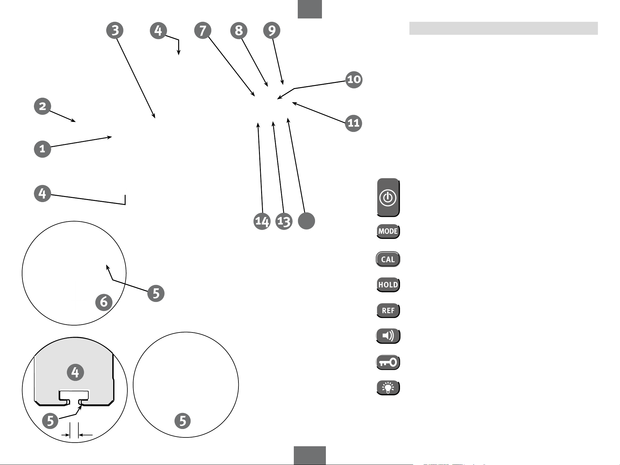
3. Components of the unit
(1)
TECH 500 DP
(dust-proof and waterproof in accordance with IP 65)
(2)
Battery compartment lid
(3)
Display
(4)
T-groove profile for securing with M4 groove stones, e.g.
Bosch Rexroth® or square nut in accordance with DIN 557
(5)
V-shape for aligning on round surfaces
(6)
Rare-earth magnet
Buttons:
(7)
On/Off
12
Units of measurement: °, %, mm/m, in/ft
(8)
Calibration and sensor adjustment
(9)
HOLD – locking measurements
(10)
Reference – freely selectable zero position
(11)
Acoustic guidance
(12)
Key lock
(13)
Display lighting
(14)
3.5 mm
4
TECH 500 DP
en
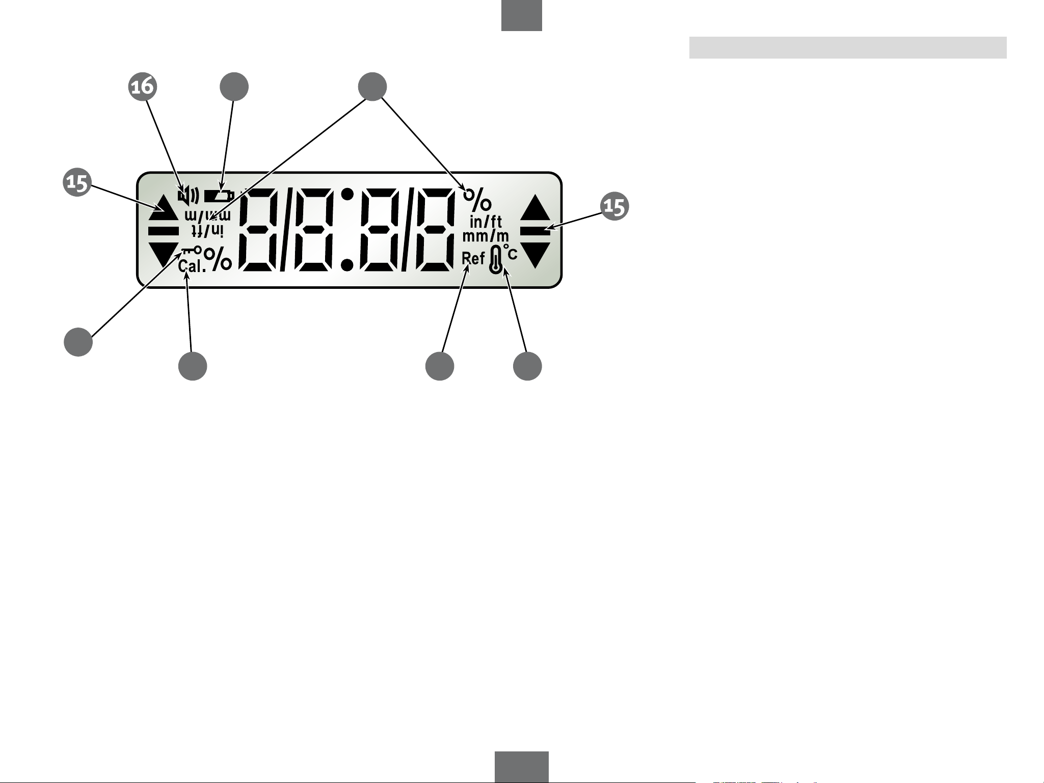
4. Display elements
22
21
17
18
20
19
(15)
(16)
(17)
(18)
(19)
(20)
(21)
(22)
Elements for visual guidance
Acoustic guidance: activated
See chapter 5.1
Units of measurement: °, %, mm/m, in/ft
See chapter 7.4
Reference: activated
See chapter 7.4
Key lock: activated
5

TECH 500 DP
en
5. Commissioning
5.1 Inserting batteries/battery replacement
Unscrew battery compartment lid, insert new batteries into
battery compartment according to symbol.
Suitable rechargeable batteries can also be used.
LCD indicator:
Battery low – insert new batteries
Alkaline
Dispose of used batteries at suitable collection
points – not with household waste. Do not
leave in unit!
If you do not intend to use the unit for an
extended period, remove the batteries.
5.2 Switching the unit on
After switching on with the "ON/OFF" button, an automatic
test is carried out. All the display's segments are shown.
After the end of the test, the version number S x.xx of the
software is briefly displayed and the automatic switch-off
time (Auto OFF) is shown.
An acoustic signal indicates that the unit is ready for
operation.
The display shows the angle measured in the set unit of
measurement.
6
 Loading...