

Stabila LAR 350 User Manual

LAR 350
Operating Instructions
www.stabila.com

LAR 350
en
Contents
Section Page
• 1. Intended Use
• 2. Safety Information 4
• 3. Before First Use 4
• 4.1 System Elements 5
• 4.2 Remote Control Unit Elements 6
• 5. Battery Insertion/Replacement 7
• 6. Using the Laser Unit 8
• 7. Tilt function 9
• 8.1 Automatic Operation with Tilt Function 10
• 8.2 Automatic Operation with Relevelling 11
• 9.1 Manual Operation with Tilt Function 12
• 9.2 Manual Operation without Tilt Function 13
• 10. Functions 14
• 11. Operation with Remote Control 16
• 12. Settings and Applications 17
• 13. Rotation Function/Rotation Speed 17
• 14. Line Function in Scan Mode 18
3
• 15. Inclining the Laser Axes 19
• 16.1 Vertical Function 20
• 16.2 Positioning Aid in Vertical Mode 20
• 16.3 Rotating and Inclining the Laser Axes 21
• 17. Positioning the Laser Beam 22
• 18. Displaying the Alignment of the Laser Axes 23
• 19. Standby Mode 23
• 20. Section Mode 24
• 21. LED Indicators 25
• 22.1 Checking Accuracy 26
• 22.2 Horizontal Check 27
• 22.3 Adjustment - Horizontal 28
• 22.4 Vertical Check 29
• 22.5 Adjustment - Vertical 30
• 23 Care and maintenance 31
• 24. Recycling Programme for our EU Customers 31
• 25. Technical Data 31
2
• 26 Declaration of warranty by STABILA Laser 31
LAR 350
en
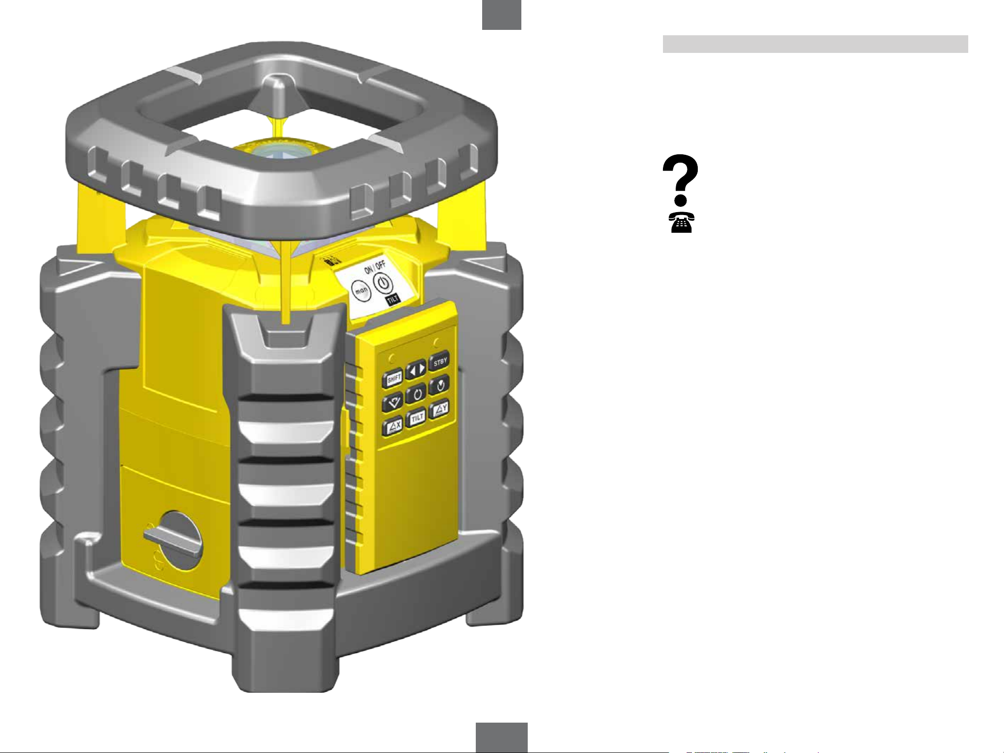
1. Intended Use
The STABILA LAR-350 is an easy-to-use rotation laser for
horizontal and vertical levelling, including obtaining plumb
lines. The LAR-350 has a sealed enclosure (IP 65) for use on
construction sites. It is self-levelling within a range of ± 5°.
The laser beam can be picked up using a receiver even
where it can no longer be discerned with the naked eye.
If you still have questions aer reading through the
operating instructions, you can obtain advice by
telephone:
0049 / 63 46 / 3 09 - 0
3
LAR 350
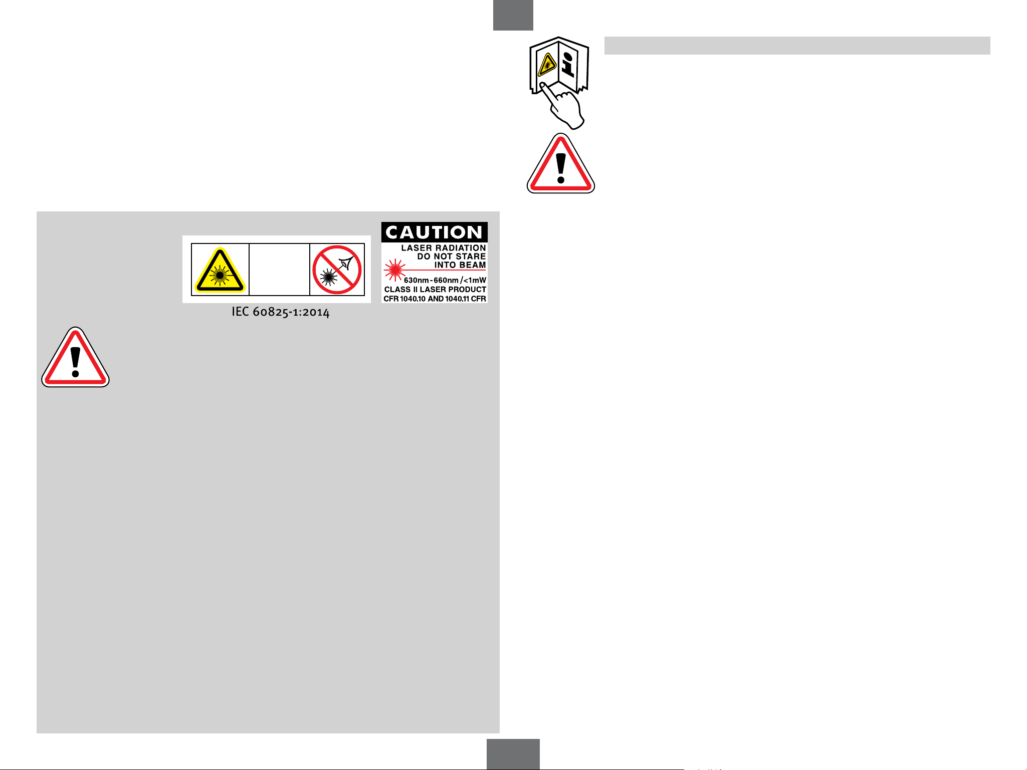
2. Safety Information
en
3. Before First Use
Read the safety instructions and operating instructions through carefully.
Allow only qualied persons to operate the unit.
Ensure that the safety precautions are observed!
To insert batteries -> Battery replacement
LASER
2
Warning:
With class 2 laser devices it is usual, in the event of an accidental brief
glance into the laser beam, for the eye to protect itself by the lid closure
reflex and/or by an natural reaction of turning away. If laser radiation
enters your eye, you should deliberately close your eyes and immediately
move your head away from the beam. Do not look into the direct or reflected beam.
The STABILA laser goggles available for our laser devices do not constitute safety eyewear;
their function is to improve the visibility of the laser beam.
• Do not aim the laser beam directly at people.
• Avoid dazzling other people with the unit.
• Keep the unit out of the reach of children.
• If other operating or adjustment equipment is used than that specified here or if
the unit is operated in ways other than described here, this may result in hazardous
exposure to laser radiation.
• No manipulation (modification) of the laser unit is permitted.
• If the unit is dropped or subjected to strong vibrations it may malfunction.
• Always check that the unit is functioning correctly and accurately before you start work,
particularly if it has been exposed to heavy vibrations.
• Do not use in explosive or corrosive environments.
• Do not dispose of the batteries or unit with domestic waste.
• Keep this user manual in a safe place. If the laser unit is passed or sold on to another
person, ensure that the manual is included with the unit.
4
LAR 350
en
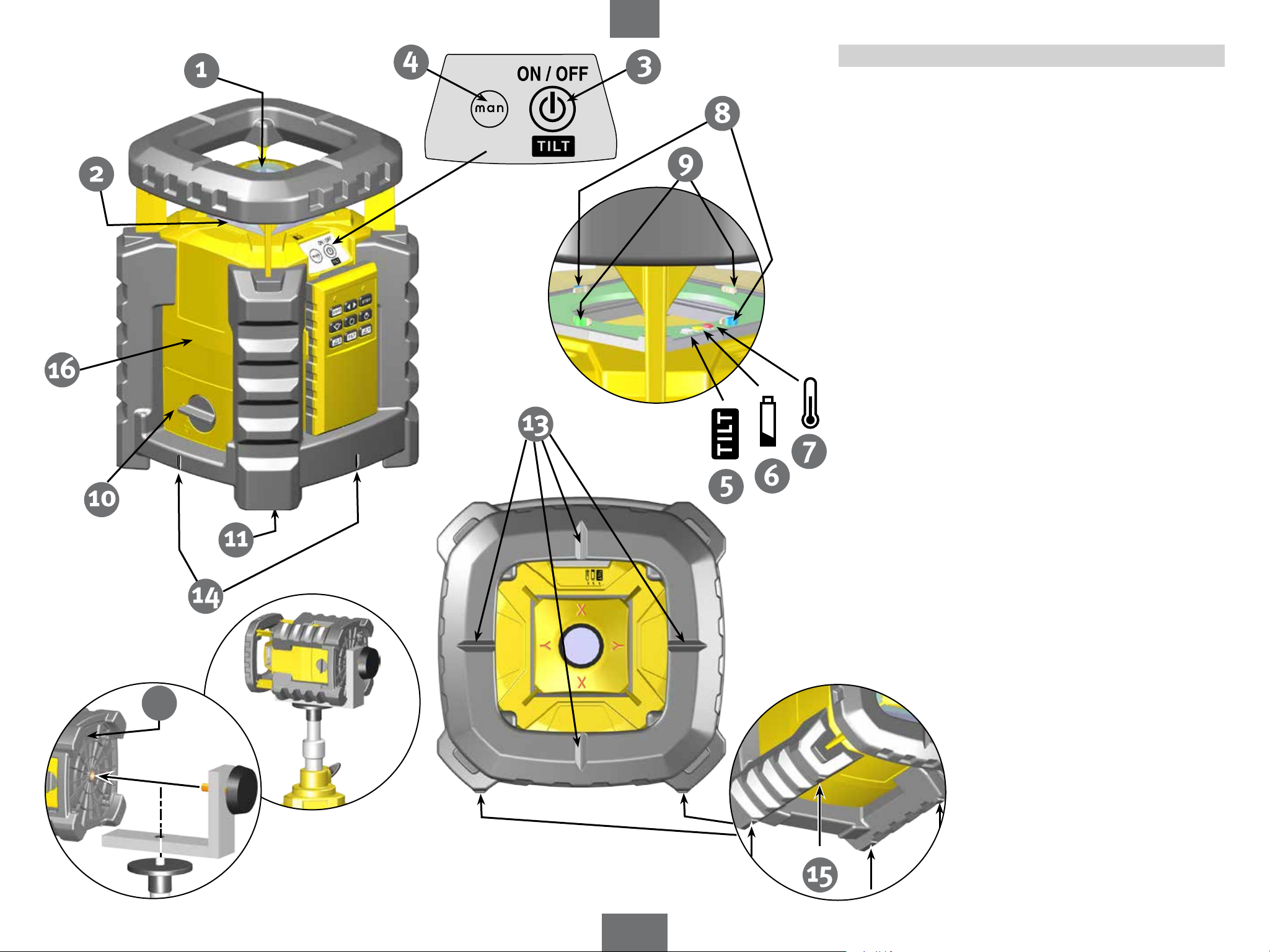
4.1 System Elements
1. Exit window Point laser/laser beam
2. Exit window Rotation beam
3. Button: ON/OFF/TILT
4. Button: Manual mode ON/OFF
5. White LED: Tilt function
6. Yellow LED: Battery low
7. Red LED: Overtemperature
8. Blue LED: Laser x-axis/display TILT + Manual
9. Green LED: Laser y-axis/display TILT + Manual
10. Battery compartment lid
11. 5/8" tripod socket
12. Retaining bracket
13. Locator markings
14. Plumb-line laser function marking points
xx
15. Feet to allow vertical alignment
16. Housing
- IP 65 protected against water jets and dust
xx Serial number
5
LAR 350
en
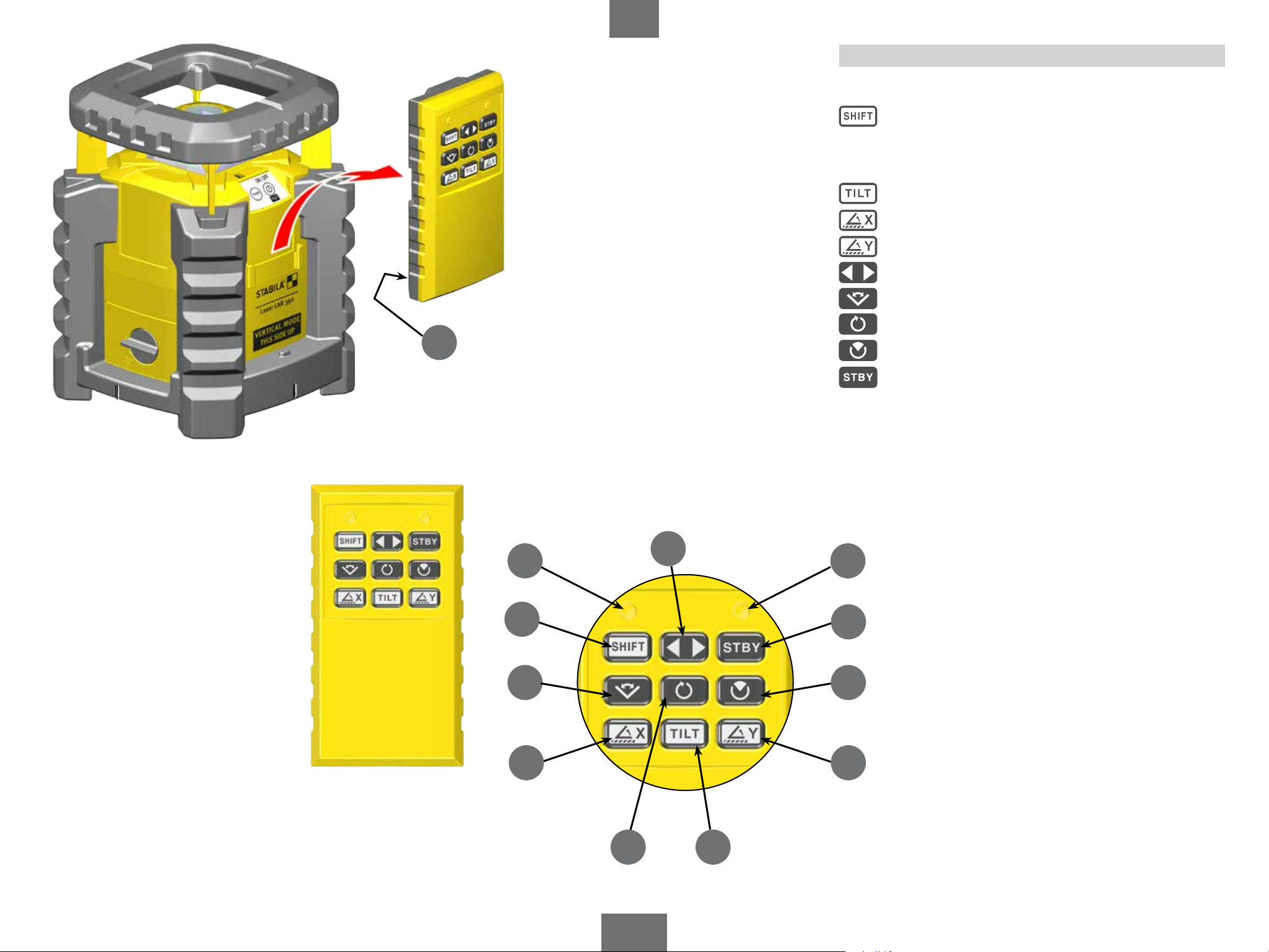
4.2 Remote Control Unit Elements
Remote control unit:
17. SHIFT
18. LED indicator for SHIFT button
19. LED indicator: transmitting
20. TILT
21. Laser x-axis
22. Laser y-axis
23. Position
24. Scan
25. Rotation speed
28
18
17
24
26. Section
27. Standby
28. Battery compartment lid
23
19
27
26
21 22
25
6
20
LAR 350
en
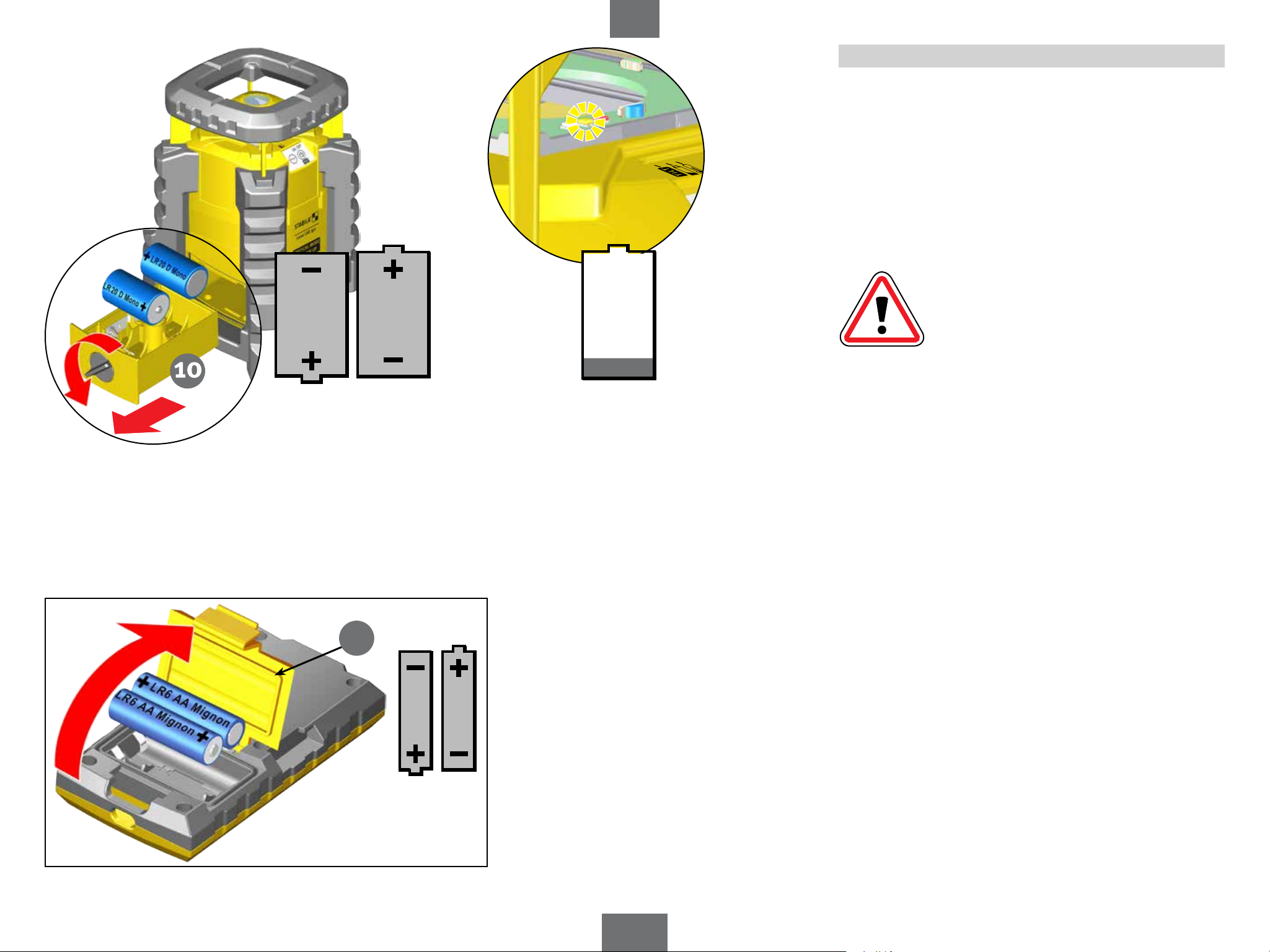
5. Battery Insertion/Replacement
Open battery compartment cover (10, 28) in the direction
of the arrow and insert new batteries as indicated by the
symbol in the battery compartment.
Suitable rechargeable batteries can also be used.
LED indicator:
Yellow LED (6): Battery capacity low
- insert new battery
2x 1.5V
Alkaline
D, LR20, Mono
Used batteries should be disposed of at
appropriate collection points. Do not dispose
of in household waste.
If you do not intend to use the unit for an
extended period, remove the batteries.
28
2x 1.5V
Alkaline
AA, LR6,
Mignon
7
LAR 350
(3)
1x
en
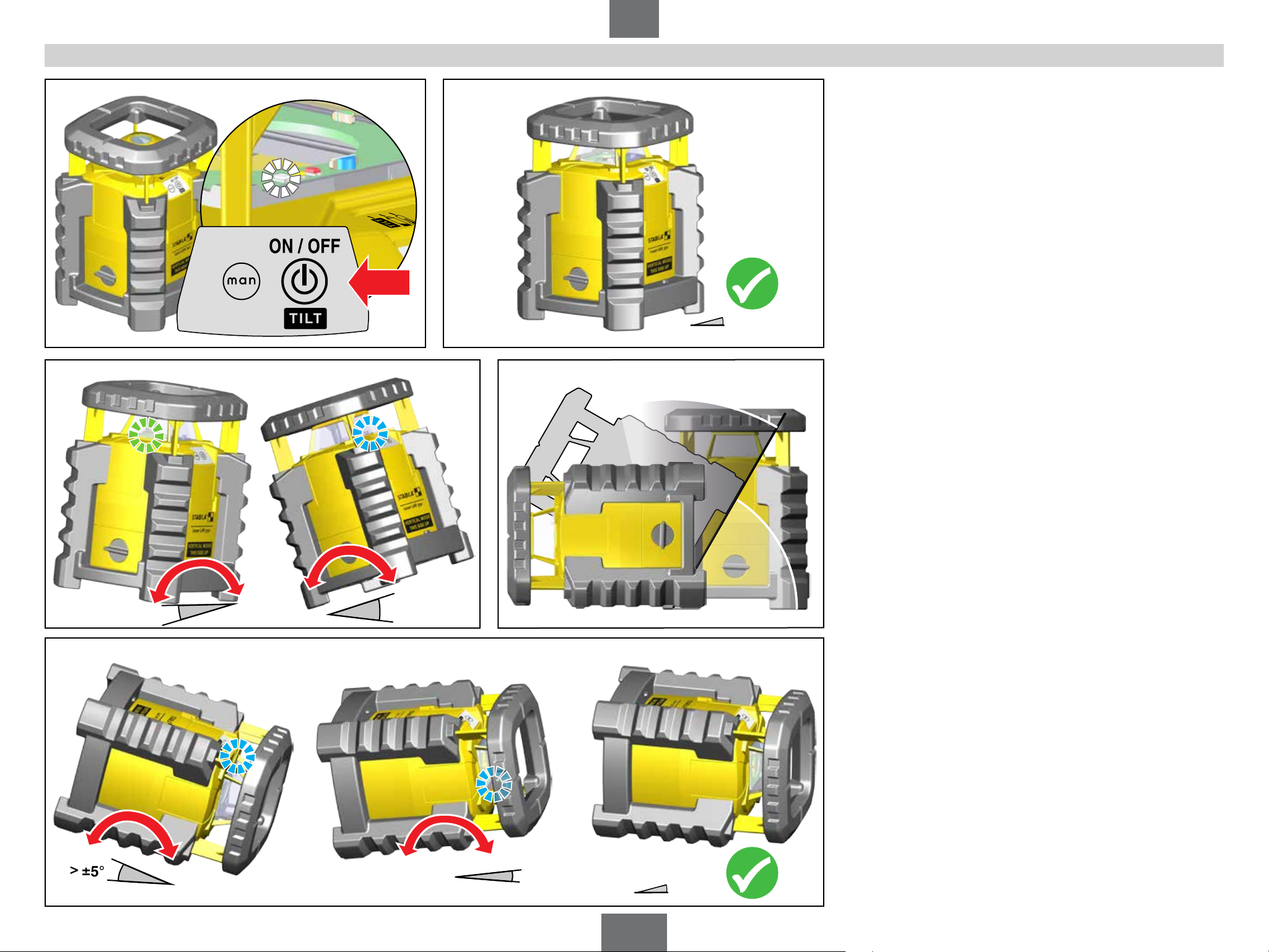
6. Using the Laser Unit
Place the laser unit in the appropriate working position
(vertical or horizontal). To start the laser, press button (3).
Holding this button for a longer period will switch the laser
o again. Activating the self-levelling function causes the
unit to level itself automatically. The laser beam does not (yet)
flash or rotate. Once levelling is completed, the beam stays
on constantly and begins to rotate. Fine adjustments can
still be made within the rst 30 seconds. These 30 seconds
are indicated by a slow flashing of the white LED (5).
If the unit is out of alignment by ≥ 5°, it is outside the
self-levelling range and cannot level itself automatically.
In this case the laser continues to flash.
>
±5°
>
±5°
<
±5°
The blue and green LEDs indicate which side of the unit is
too high. Adjust the unit by hand until the LEDs go out.
In vertical operation the device detects the alignment
automatically.
>
±5°
>
±5°
8
<
±5°
LAR 350
(3)
en
1x
1x
1x
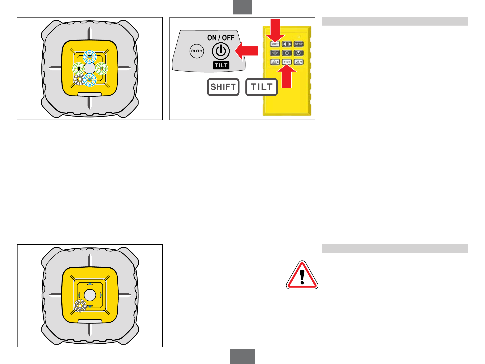
7. Tilt function
The tilt function warns if any interference to the laser has
occurred that may cause misalignment. This ensures that
such interference does not go unnoticed.
When the tilt function is active, the white LED (5) is lit
steadily. If any event occurs that could result in the laser
unit being deflected from its exact alignment and setting,
the beam ceases to rotate and the blue (8) and green (9)
LEDs flash. If this occurs, check the laser unit and set it up
once again if necessary.
(17) (20)
If the tilt function is triggered, this must be acknowledged
by pressing button (3) or, on the remote control unit, by
pressing buttons (17) + (20). Only aer this can you proceed
further.
The tilt function can be switched on or o in any mode
(touch button (3) briefly). When the laser unit is switched
on (button 3), tilt mode is always initially activated.
9
Deactivated tilt function
If the tilt function is deactivated (white LED flashing),
no warning is given of any change in the setting/alignment
in the event of interference. In automatic operation,
however, the unit re-levels itself automatically.
LAR 350
(4)
(3)
1x
en
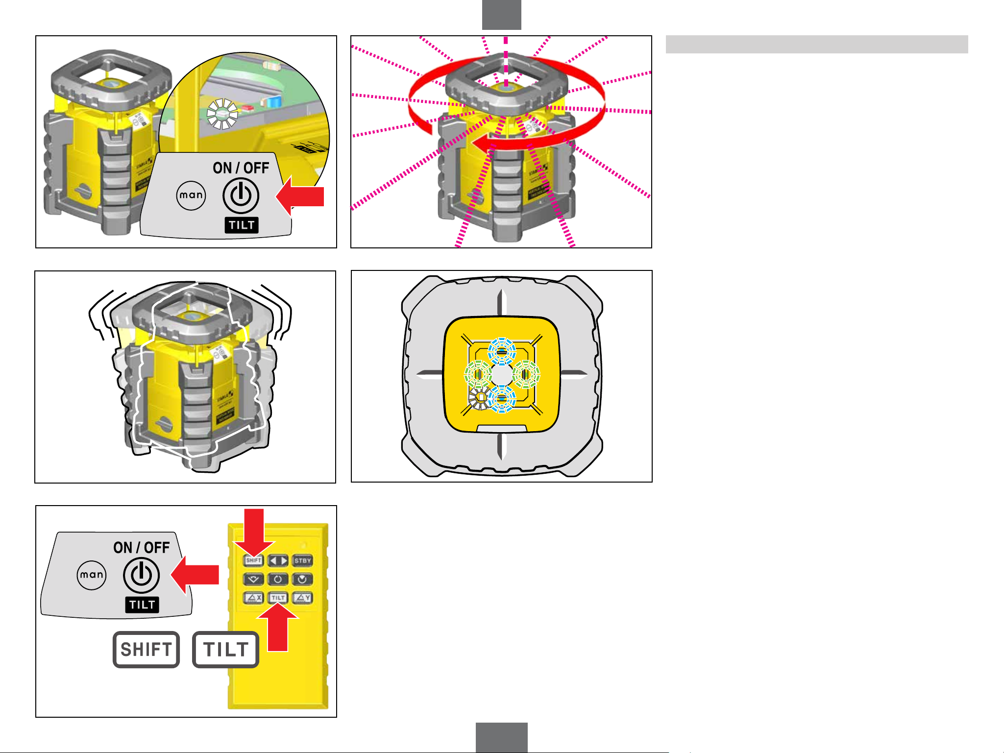
8.1 Automatic Operation with Tilt Function
This mode is always set directly aer the unit is switched
on (button 3). Other modes can be selected by pressing
button (3) or button (4) or using the remote control unit.
In ‘Automatic’ mode the laser unit levels itself automatically.
Place the laser unit in the appropriate working position
(vertical or horizontal). To switch on, press button (3) once.
Now the LAR 350 is in ‘Automatic mode with tilt function’.
The automatic levelling process begins. Once levelling is
completed, the beam stays on constantly and begins to
rotate. Fine adjustments can still be made within the rst
30 seconds. These 30 seconds are indicated by a slow
flashing of the white LED (5).
When the tilt function is active, the white LED (5) is lit
steadily. If any event occurs that could result in the laser
unit being deflected from its exact alignment and setting,
the beam ceases to rotate and the blue (8) and green (9)
LEDs flash. If this occurs, check the laser unit and set it up
once again if necessary.
(3)
If the tilt function is triggered, this must be acknowledged
by pressing button (3) or, on the remote control unit, by
pressing buttons (17) + (20). Only aer this can you proceed
further.
If you are working in conditions where interference is present
(e.g. on vibrating surfaces), it is recommended that you
select ‘Automatic operation with relevelling’.
1x
1x
(17) (20)
1x
10
 Loading...