

Stabila LAR 300 Operating Instructions Manual
Operating instructions

en
Contents
Section Page
• 1. Intended use 3
• 2. Safety instructions for laser units 4
• 3. Before first commissioning 4
• 4. Components of the unit 5
• 5. Battery insertion/replacement 6
• 6. Commissioning 7
• 7. Tilt function 8
• 8.1 Automatic operation with tilt function 9
• 8.2 Automatic operation with relevelling 10
• 9.1 Manual operation with tilt function 11
• 9.2 Manual operation without tilt function 12
• 10. Functions 13
• 11. LED indicators 14
• 12.1 Checking accuracy 15
• 12.2 Horizontal check 15
• 13. Technical data 16
2

en
1. Intended use
The STABILA LAR 300 rotation laser is an easy-to-use rotation
laser for horizontal levelling and establishing plumb lines.
The LAR 300 has a sealed enclosure (IP 65) for use on building sites. It is self-levelling within a range of ± 5°.
The laser beam can be picked up using a receiver even where
it can no longer be discerned with the naked eye.
If you still have questions aer reading through the operating
instructions, you can obtain advice by telephone:
+49 / 63 46 / 3 09 - 0
3
en
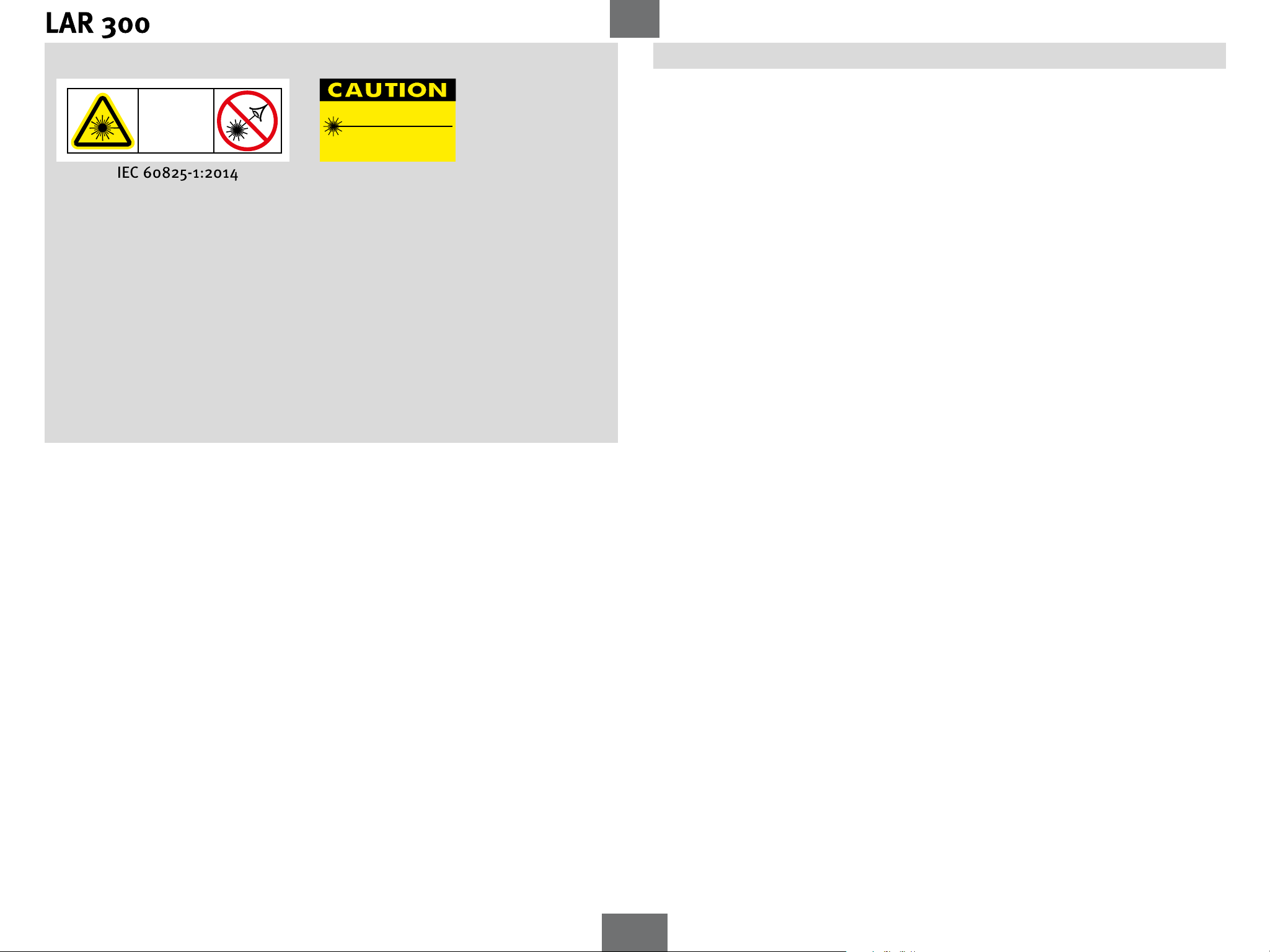
2. Safety instructions for laser units
LASER
2
In Class 2 laser units, your eyes are usually protected from accidental, short-term exposure to the laser beam by the eyelid-closing reflex and/or the reflex reaction to turn
one’s head. If a laser beam hits your eye, deliberately close your eyes and move your
head out of the path of the beam. Do not look into the direct or reflected beam.
The STABILA laser goggles available for our laser units are not safety eyewear:
their function is to improve the visibility of the laser beam.
LASER RADIATION
DO NOT STARE INTO BEAM
510 - 635 nm / <1mW
CLASS II LASER PRODUCT
CFR 1040.10 AND CFR 1040.11
• Do not aim the laser beam directly at people!
• Avoid dazzling other people with the unit!
• Keep the unit out of the reach of children!
• If operating or adjustment equipment that has not been specied here is used, or
if the unit is not operated in the ways described here, this may result in hazardous
exposure to radiation!
3. Before rst commissioning
To insert batteries -> Battery replacement
4

en
4. Components of the unit
1. Exit window Point laser/laser beam
2. Exit window Rotation beam
3. Button: ON/OFF/TILT
4. Button: Manual mode ON/OFF
5. White LED: Tilt function
6. Yellow LED: Battery low
7. Red LED: Overtemperature
8. Blue LED: Laser x-axis/display TILT + Manual
9. Green LED: Laser y-axis/display TILT + Manual
10. Battery compartment lid
11. 5/8” tripod socket
12. Retaining bracket
13. Locator markings
14. Plumb-line laser function marking points
15. Housing
- IP 65 protected against water jets and dust
xx Serial number
5
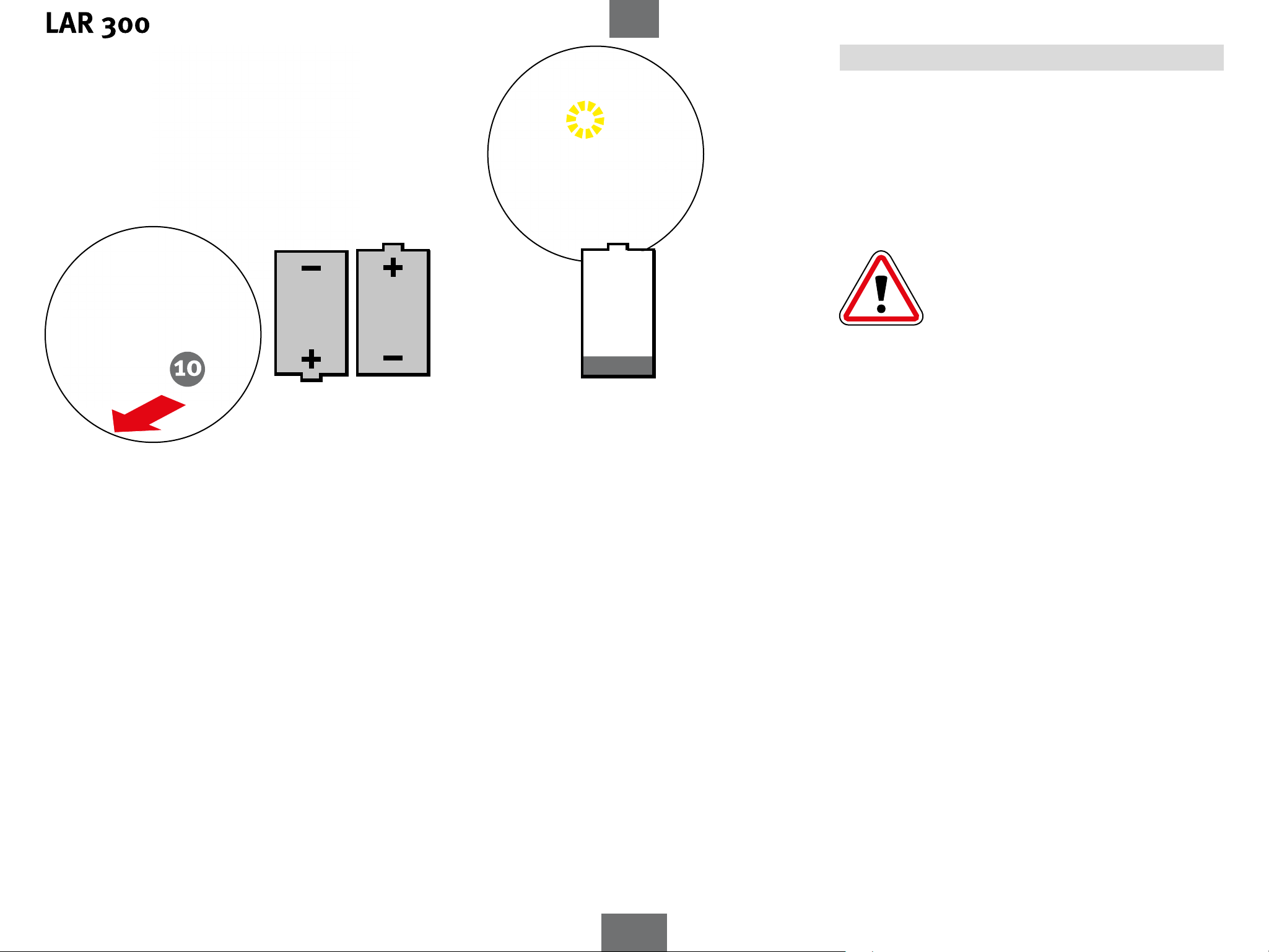
2x 1.5 V
Alkaline
D, LR20, Mono
en
5. Battery insertion/replacement
Open thebattery compartment lid (10) in the direction of the
arrow and insert new batteries in the battery compartment
as indicated by the symbol.
Suitable rechargeable batteries can also be used.
LED indicator:
Yellow LED (6): Battery capacity low
- Insert new battery
Used batteries should be disposed of at
appropriate collection points.
Do not dispose of in household waste.
If you do not intend to use the unit for an
extended period, remove the batteries.
6
 Loading...