

ST TS2431 User Manual
查询TS2431供应商
TS2431
PROGRAMMABLE SHUNT VOLTAGE REFERENCE
■ ADJUSTABLE OUTPUT VOLTAGE
2.5 to 24V
■ SEVERAL PRECISION @ 25°C
±2%, ±1% and ±0.5%
■ SINK CURRENT CAPABILITY
1 to 100mA
■ INDUSTRIAL TEMPERAT URE RANGE:
-40 to +105°C
■ PERFORMANCES COMPATIBL E WI TH
INDUSTRY STANDARD TL431
DESCRIPTION
The TS2431 is a programmable shunt voltage
reference with guaranteed temperature stability
over the entire temperature range of operation
(-40 to +105°C). The output voltage may be set to
any value between 2.5V and 24V with an external
resistor bridge.
Available in SOT23-3 s urface mount package, it
can be designed in applications where space
saving is a critical issue.
APPLICATION
L
SOT23-3L
(Plastic Micropackage)
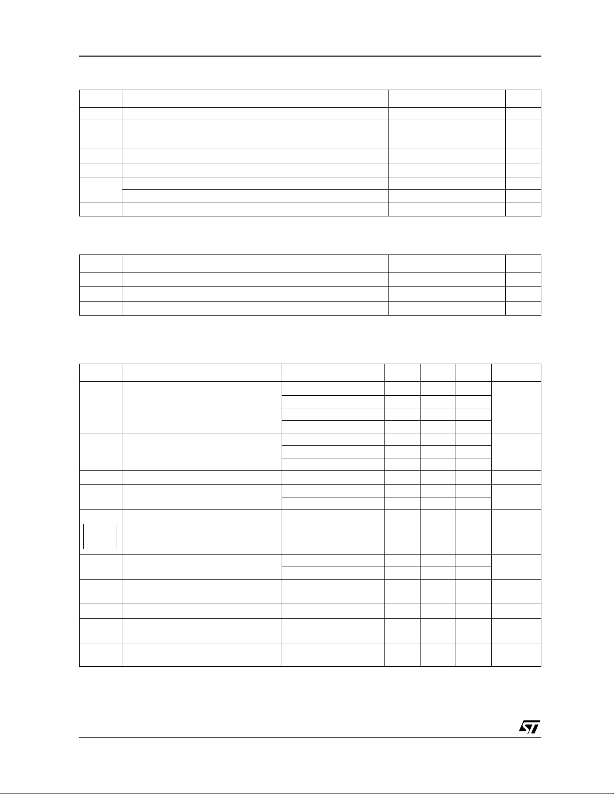
PIN CONNECTIONS (top view)
■ Computers
■ Instrumentation
■ Battery chargers
■ Switch Mode Power Supply
■ Battery operated equipments
ORDER CODE
Precision
2% TS2431ILT L285
1% TS2431AILT L286
0.5% TS2431BILT L287
Single temperature range: -40 to +105°C
LT = Tiny Package (SOT23-3) - only available in Tape & Reel (LT)
February 2002
Part Number
in SOT23-3
SOT23
Marking
Cathode
Reference
1
3
TS2431
2
SOT23-3
Anode
1/6
TS2431
ABSOLUTE MAXIMUM RATINGS
Symbol Parameter Value Unit
Vka Cathode to Anode voltage 25 V
I
Reverse Breakdown Current -100 to +150 mA
K
I
T
ESD
T
LEAD
1. Pd has been ca l culated wi th Ta mb = 25°C, Tjunction =150°C and Rth j a = 340°C/W for the SOT23-3 package
OPERATING CONDITIONS
Symbol Parameter Value Unit
V
T
1. Maximum power dissipation must be st ri ctly obser ved to avoid t he component destruction.
Reference input current range -0.05 to +10 mA
REF
P
Power Dissipation
d
Storage Temperature -65 to +150 °C
std
1)
SOT23-3
360 mW
Human Body Model (HBM) 2 kV
Machine Model (MM) 200 V
Lead Temperatue (soldering, 10 seconds) 260 °C
to 24
Cathode to Anode voltage
KA
I
Cathode operating current
K
Operating Free Air Temperature Range -40 to +105 °C
oper
1)
V
REF
1 to 100 mA
V
ELECTRICAL CHARACTERISTICS
T
AMBIENT
Symbol Parameter Test Condition Min. Typ. Max. Unit
V
|∆
I
∆Vref
---------------
∆Vk
|∆
= 25°C (unless otherwise specified)
Reference input Voltage VK=V
REF
Reference input Voltage deviation over
temperature, V
V
T
KMIN
I
REF
I
REF
I
OFF
Z
|
KA
E
|
REF
(note 1,2)
Temperature coefficient (note 2) -40°C < T < +105°C 50 100 ppm/°C
C
Minimum Operating Current
Ratio of change in reference input
voltage to change in catho de to anode
voltage
Reference input current
I
=10mA, R1=10K
K
Reference input current deviation
|
I
=10mA, R1=10K
K
Off-state cathode current
|
Reverse dynamic impedance
Wide Band Noise
N
, IK=10mA
K=VREF
R2=+ (note 3)
Ω,
R2=+ (note 3)
Ω,
, IK=10mA
REF
2.5
TS2431 (2%) 2.45 2.55
TS2431A (1%) 2.475 2.525
TS2431B (0.5%) 2.488 2.512
0°C < T < +70°C 10 20
-40°C < T < +105°C 20 35
T = 25°C 0.3 0.8
-40°C < T < +105°C 1
I
=10mA
K
Vka= 24 to 2.5V
0.3 2 mV/V
T=25°C 0.5 2.5
∞
∞
-40°C < T < +105°C 3
-40°C < T < +105°C 0.4 1.2 µA
=24V, V
V
K
V
K=VREF
I
∆
=1 to 50mA, f<10kHz
K
Ik = 10mA
10Hz < f < 10kHz
REF
=GND
10 500 nA
0.5 0.75
300 nV/√Hz
V
mV-40°C < T < +85°C 17 30
mA
µA
Ω
Note 1: Limits are 100% production tested at 25°C. Limits over temperature are guaranteed through correlation and by design.
Note 2:
Note 3: Refer to figure "Test circuit for Vka>Vref" page 4
V
|∆
| is defined as the difference between the maximum and minimum values of V
REF
obtained over the full temperature range
REF
2/6
 Loading...