

Page 1

USER MANUAL
Suzhou Sate Auto Electronic Co., Ltd
www.sate.com.cn
----------------------------------------------------------------------------------------------------------------------
Table of Contents
I. S&T TPMS1209C01, Full-time Direct TPMS------------------------------------------------------------------2
II. Parts of TPMS1209C01-------------------------------------------------------------------------------------------2
III. Installation of TPMS1209C01-----------------------------------------------------------------------------------4
Installation of Monitor------------------- -----------------------------------------------------------------------------4
Installation of Transmitter--------------------------------------------------------------------------------------------4
Installation of Counterweight ---------------------------------------------------------------------------------------6
IV. St an dar d Pressure Inquiry and Programming------ ------------------------------ ----------------------------- 6
Access of Programming Index Interface--------------------------------------------------------------------------6
Standard Pressure Inquiry --------------------------------------------------------------------------------------------7
Standard Pressure Programming------------------------------------ -------------------------------------------------8
V. System Time Inquiry and Programming-------------------------------------------------------------- -----------9
System Time Inquiry --------------------------------------------------------------------------------------------------9
System Time Programming------------------------------------------------------------------------------------------10
VI. System Functions---------------- ------------------------------------------------------ ---------------------------10
VII. Pressure and Temperature Unit Inquiry and Programming-------------------------------------------------15
Pressure and temperature unit inquiry-------------------------------------------------------------------------------15
Pressure Unit Programming-------------------------------------------------------------------------------------------16
Temperature Unit Programming--------------------------------------------------------------------------------------16
VIII. New Transmitter Adding or Transmitter Replacement------------------------------------------------------17
IX. Deletion of Transmitter ID------------------------- -------------------------- -------------------------------------20
X. Specifications -------------------------------------------------------------------------------------------------------22
XI. Special Annex------------------------------------------------------------------------------------------------------22
XII. Frequently Asked Questions ------------------------------------------------------------------------------------22
XIII. W ar ranty Term ------------- -------- -------- ---------- -------- -------- ---------- -------- -------- ---------- -------- 23
XIV. Important Notes---------------------------------------------------------------------------------------------------23
Page 2
TPMS1209C01 User Manual
Page 2 of 23
I. S&T TPMS1209C01 Full-Time Direct TPMS
TPMS1209C01 is a full-time direct tire pressure monitoring system including one wireless Monitor and
four screw-on Transmitters. The system can also support monitoring of the spare tire and a two-tire trailer
if needed. But this requires purchase of extra replacement transmitter. The Transmitters can be screwed
onto the tire valve to replace the original valve cap to sense the pressure insid e the tire all the time, and
transmit the pressure information data to the Monitor by RF technology.
The Monitor receives the data and displays the pressure on the screen. The Monitor will issue different
alarms if the tire pressure is over or under an improper state based on the standard pressure.
S&T TPMS1209C01 will sense and display the tire pressure and temperature all the time and can issue an
alarm when the tire pressure or temperature is at an improper level, so as to notify the driver to treat the
problem and prevent tire damage. With the TPMS1209C01, the driver can monitor the pressure and
temperature to avoid excess gasoline consumption and keep the vehicle at the proper pressure.
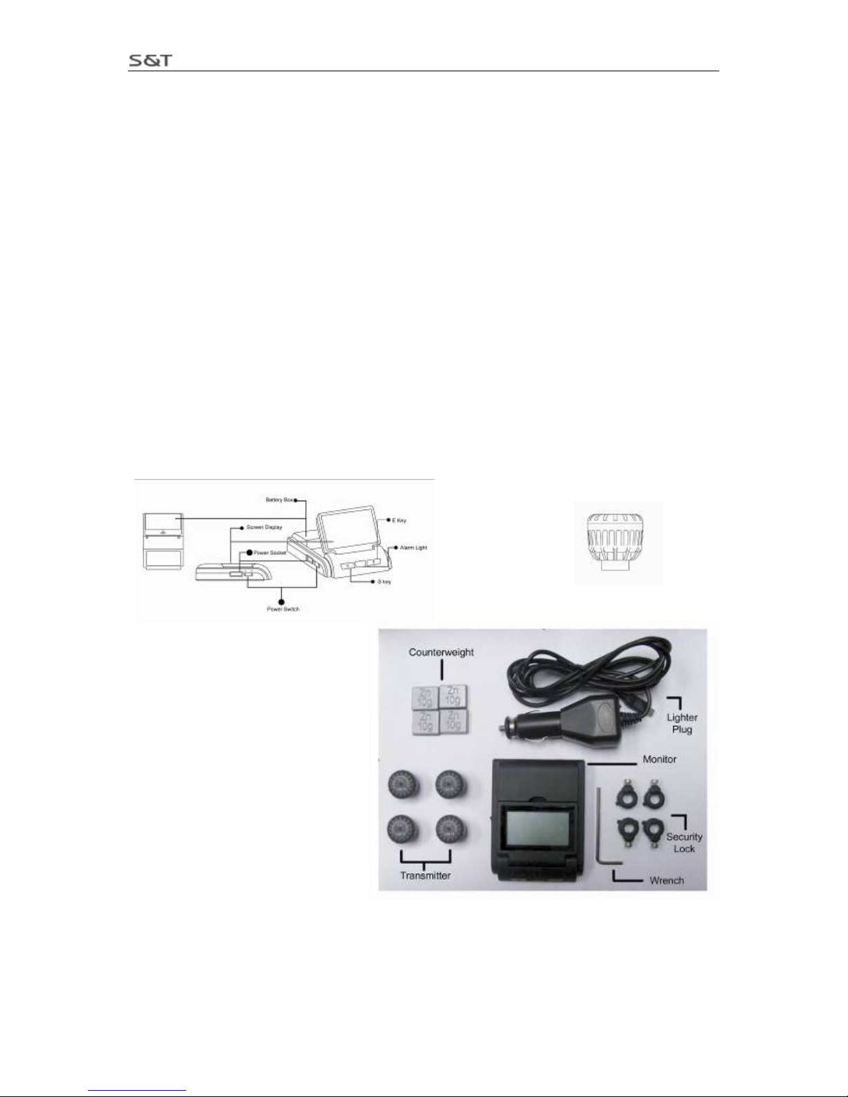
----------------------------------------------------------------------------------------II. Parts of S&T TPMS1209C03
Monitor Transmitter
TPMS1209C01 Parts
1 Monitor
4 Transmitters
4 Security Locks
1 Lighter Plug
4 Counterweights (each 10g)
2 Wrenches
1 User Manual
1 W arranty Card
Page 3
TPMS1209C01 User Manual
Page 3 of 23
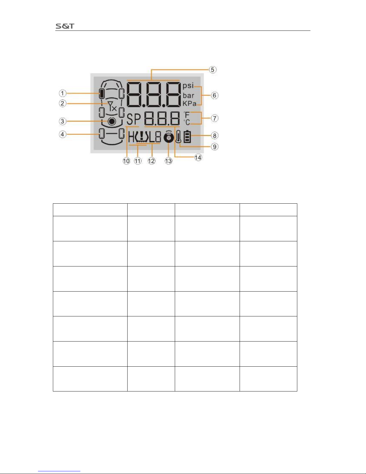
Screen Display
No. Meaning No. Meaning
⑴ Tire position Icon Current tire
information
(8) Battery Power
Icon
Battery power
indication
⑵ Transmitter Trouble Icon Transmitter
trouble
⑼ High Temperature
Alarm Icon
High temperature
alarm
⑶ Spare Tire Icon Spare tire
position
(10) Standard
Pressure Icon
Standard pressure
⑷ Trailer Icon Trailer tire
position
(11) High Pressure
Alarm Icon
High pressure
alarm
(5) Pressure Pressure value (12) Low Pressure
Icon
Low pressure
alarm and level
(6) Pressure Unit Pressure unit,
bar/Kpa/ psi
(13) Fast Leak Icon Fast leak alarm
(7) Temperature Unit Temperature
unit, /℃℉
(14) Temperature
value
Temperature
Page 4
TPMS1209C01 User Manual
Page 4 of 23
III. Installation of TPMS1209C01
Installation of Monitor
1. Take out the Monitor from the package.
2. Choose a suitable location on the dashboard to install the monitor.
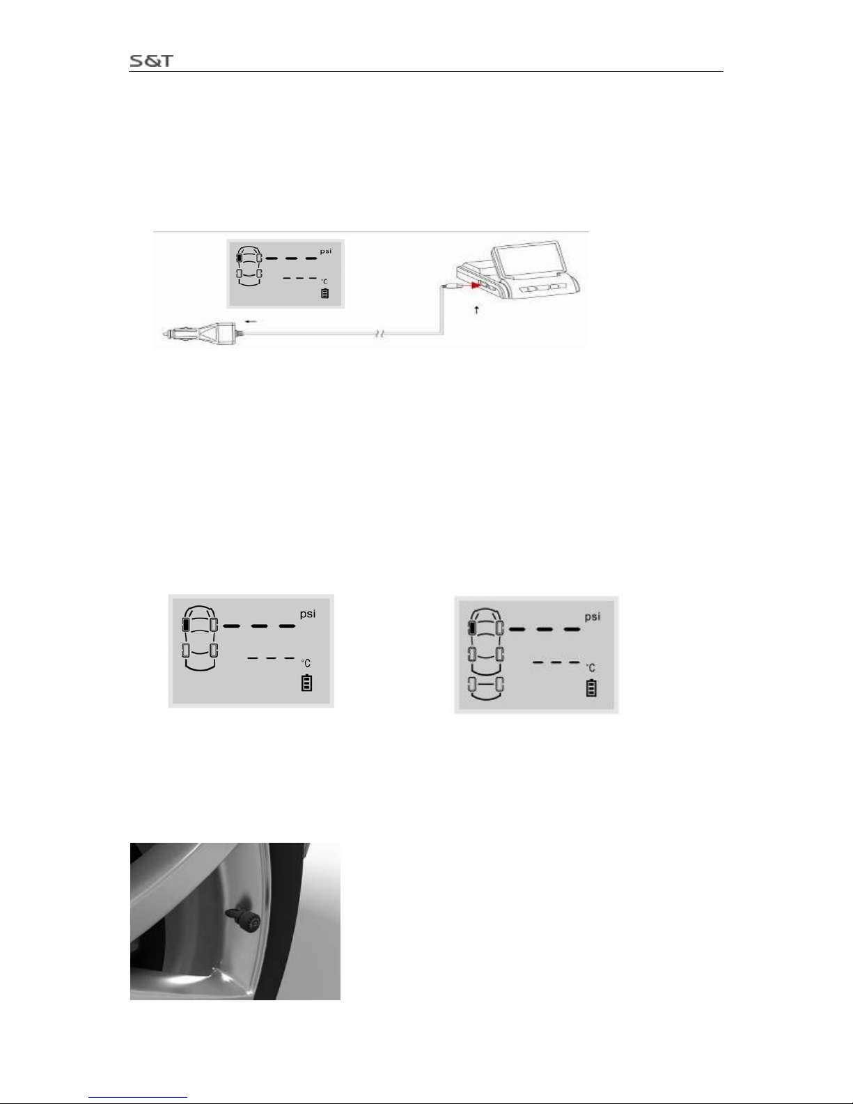
3. Connect lighter plug with vehicle power supply as shown in below figure.
If you do not find it convenient to use the lighter plug, the battery is an option for powering the Monitor.
User only needs to put two AA batteries into the battery box according to the correct direction of the
positive and negative.
Note:
1. When use battery, please avoid the monitor being placed in the sun for long periods of as it may
cause battery leakage or damage.
2. If the vehicle is dormant for long periods of time, we suggest that the user pull out the lighter plug
or turn off the monitor.
4. Turn on the monitor by switching to “ON”. Before the transmitters are installed, the screen displays as
shown below:
Monitor for car Monitor for car towing a two-tire trailer
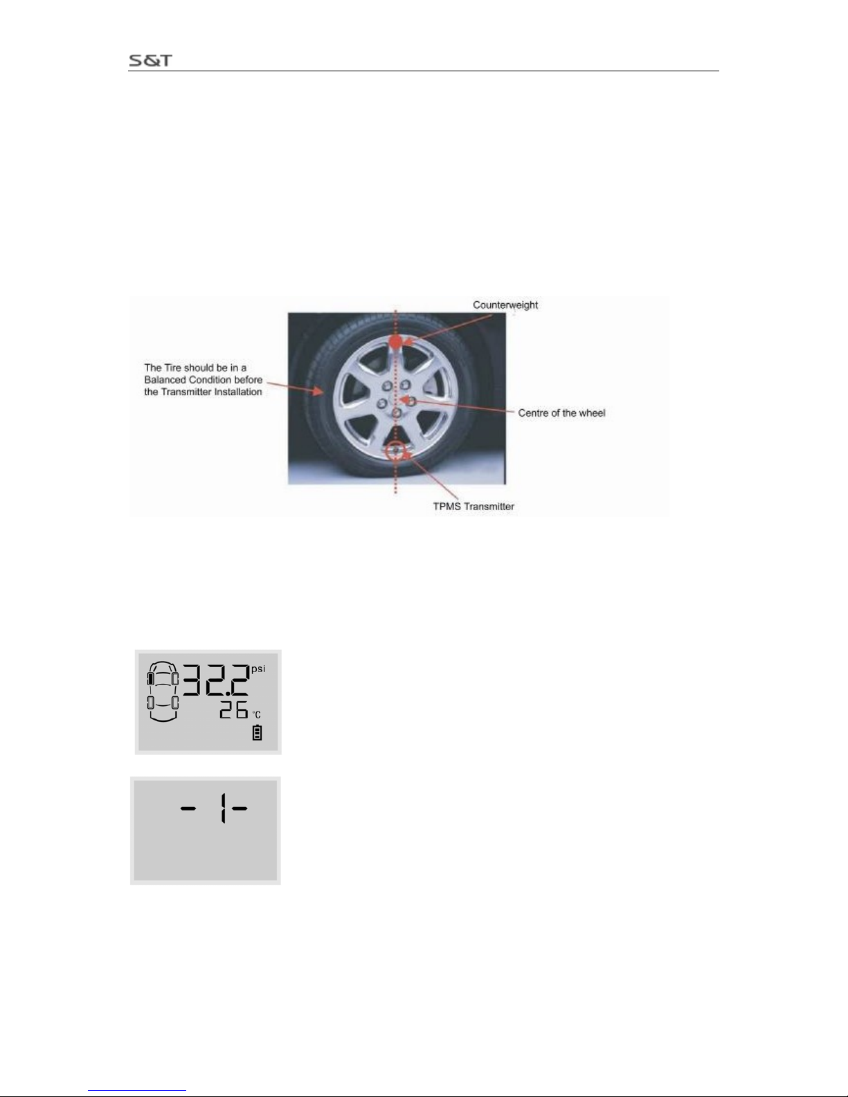
Installation of Transmitter
Transmitter installation position
Page 5
TPMS1209C01 User Manual
Page 5 of 23
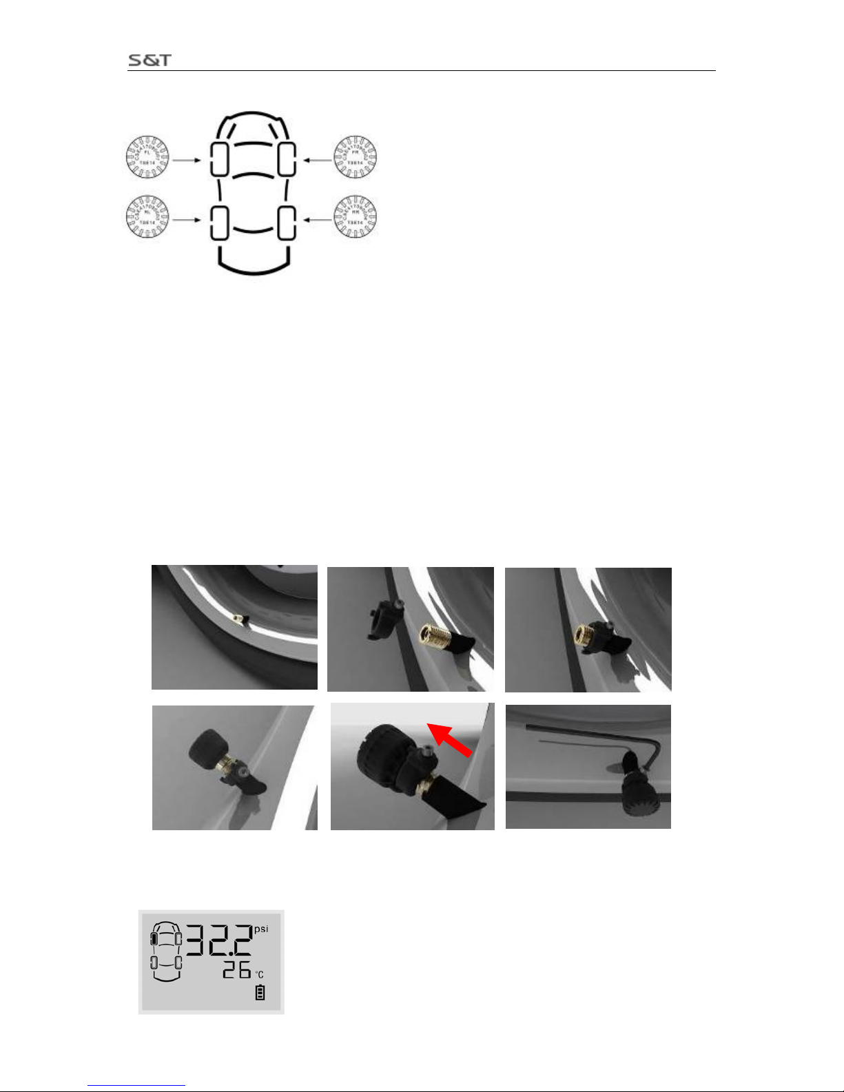
Note: The transmitters must be installed onto corresponding tire position as marked on the top.
Note: FL: stands for front left tire
FR: stands for front rear tire
RL: stands for rear left tire
RR: stands for rear right tire
If the vehicle equipped with spare tire or trailer tires, please refer to
“
VIII. Add New Transmitter or Replace Transmitter”.
Transmitter Installation steps:
1. Turn on the monitor and ensure it works normally.
2. Remove the current tire valve cap.
3. Put the security lock on the valve, ensure the side with screw to the direction which easy for operating.
4. Install the transmitter onto the valve. Ensure the transmitter being installed onto the corresponding tire
according to transmitter’s marks.
5. Connect the meshing parts of the Lock and the Transmitter to make them an integrated part.
6. Screw the transmitter and security lock firmly with the wrench.
7. After transmitters are installed, they will start working and sending signals to the monitor. As showed
below, the front left tire was installed with a transmitter and the monitor has received the information sent
by it.
Page 6
TPMS1209C01 User Manual
Page 6 of 23
The other transmitters can be installed in the same way as stated above.
Installation of Counterweights
In order to ensure that each tire remains balanced after installation of the transmitters and security locks, it
is recommended that the user should take their car to a qualified service station for re-balancing. Or the
user can install the provided counterweights inside the package to keep tires balanced. To install the
counterweight:
1. Clean the location where the counterweight will be installed. This location should be directly across the
position of the Transmitter on the wheel.
2. Take out the counte rweight from the accessory bag in the package and remove the liner material on its
back.
IV. Standard Pressur e Inquiry and Programming
Programming Index Interface
After installed the transmitters, please check the setting of standard pressure of each tire to ensure whether
it is proper, if not, please follow below steps to adjust.
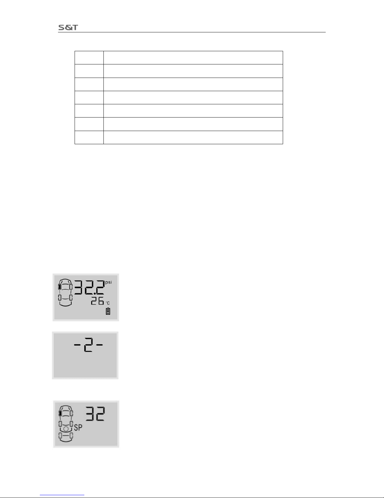
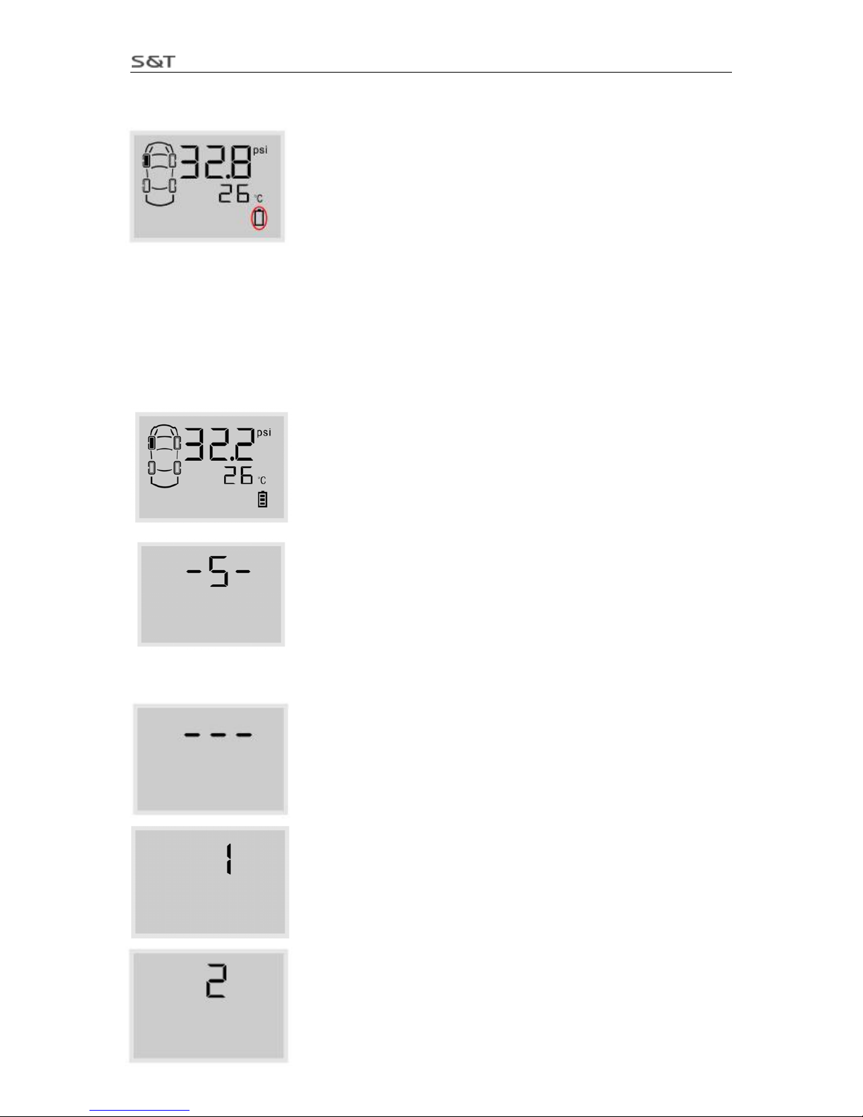
Under the normal operating mode, press the E key for 3 seconds to access
monitor programming index interface. The screen will display “-1-”
which
stands for index interface 1.
Pressure S key to switch between the interfaces from 1 to 6. Press S key for
3 seconds to exit the programming index interface and return to the normal
operation mode.
Note: If there is no operation for a certain time, the system will exit the
programming interface and return to the normal operating mode
automatically.
Page 7
TPMS1209C01 User Manual
Page 7 of 23
Below are the functions of each index interface.
Index Function
1 Transmitter ID Inquiry and Programming
2 Standard Pressure Inquiry and Programming
3 Pressure and Temperature Unit Inquiry and Programming
4 System Time Inquiry and Programming
5 Alarm Record Inquiry
6 Transmitter ID Deletion
Standard Pressure Inquiry
The pressure alarm that issued by monitor is based on the standard pressure.
The system will issue the high pressure alarm when the tire pressure is 25% higher than the standard
pressure.
The system will issue the low pressure level 1 alarm when the tire pressure is 12.5% lower than the
standard pressure.
The system will issue the low pressure level 2 alarm when the tire pressure is 25% lower than the stand ard
pressure.
The system will issue the low pressure level 3 alarm when the tire pressure is 50% lower than the stand ard
pressure.
It is necessary to set a proper standard pressure to ensure the system working normally. The default
standard pressure set in factory is 32 psi. User can adjust the standard pressure according to actual needs.
Under the normal interface, press E key for 3 seconds to enter the monitor
programming interface and display the index interface 1.
Press S key to switch to the index interface 2, then press E key to enter the
standard pressure inquiry interface.
The screen displays the standard pressure for front left tire firstly. The default
standard pressure is 32 psi.
Page 8

TPMS1209C01 User Manual
Page 8 of 23
Press S key to check each tires’ standard pressure in turn.
Under any inquiry interface, press S key for 3 seconds to return to the index
interface 2.
Standard Pressure Programming
Under the standard pressure inquiry interface, press E key for 3 seconds to
enter the standard pressure programming interface, and the first digit starts
to flash.
Press E key to switch to the next digit to program and the second digit
flashes.
Press S key to adjust the value.
After programmed the standard pressure, press E key for 3 seconds to save,
two beep are provided and screen flashes twice, then returns to the standard
pressure inquiry interface.
During the process of adjusting the standard pressure, pressing the S key
for a few seconds will return to the ind ex interface 2 and will exit and the
adjusted value will not be saved.
The maximum standard pressure value for all tires is as below:
480 Kpa
4.8 Bar
70 Psi
Page 9
TPMS1209C01 User Manual
Page 9 of 23
V. System Time Inquiry and Programming
Set the time when using the product for first time. The monitor provides 24 hours time system inquiry and
programming. Even though the monitor is powered off, the inside clock is still in operation. The alarm
information and alarm time will be saved into the monitor when alarm was issued.
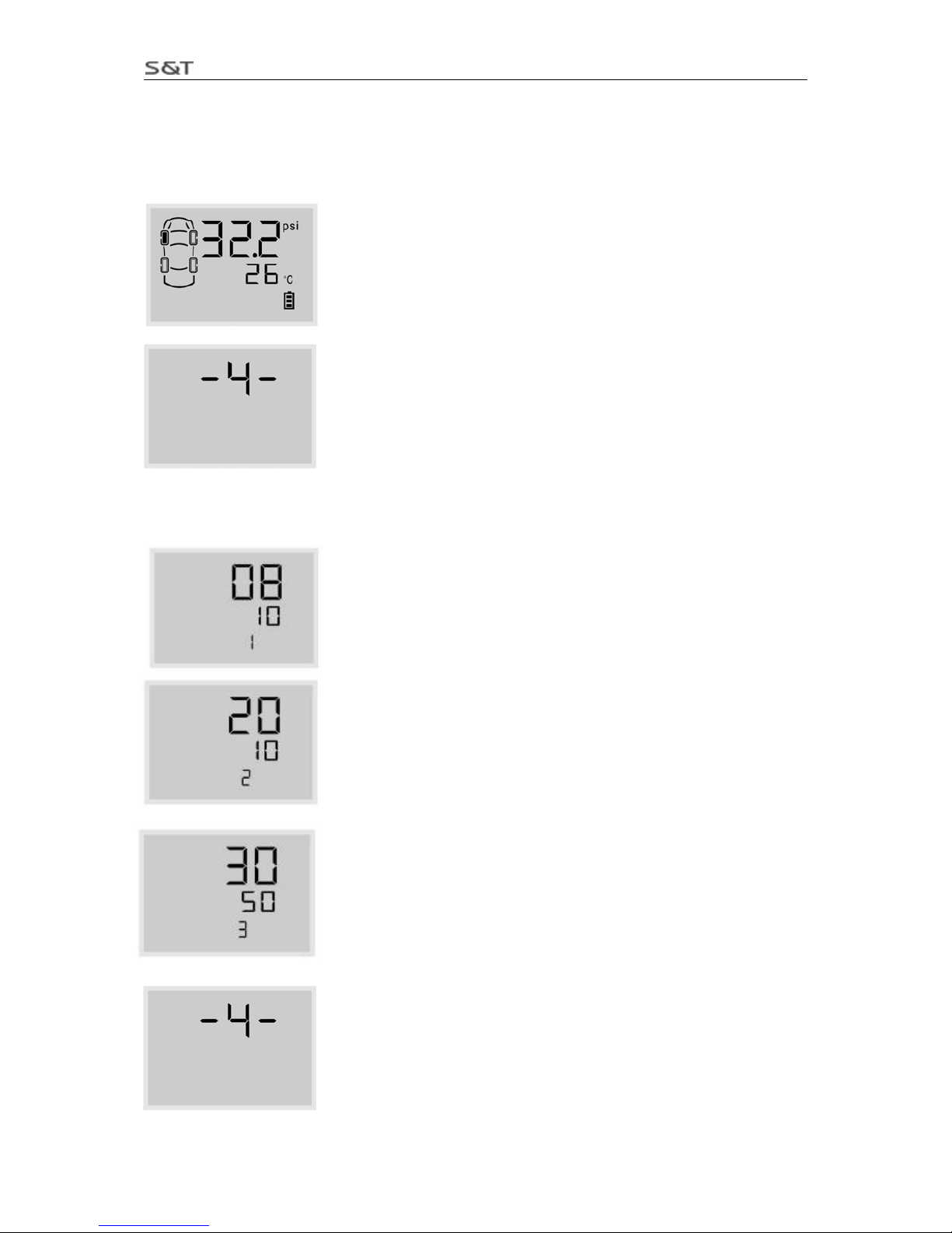
Under the normal mode, press E key for 3 seconds to enter the monitor
programming interface, the screen displays the index interface 1.
Press S key to adjust the index interface to in terface 4, then press E key to
enter the time inquiry and programming interface.
System time inquiry
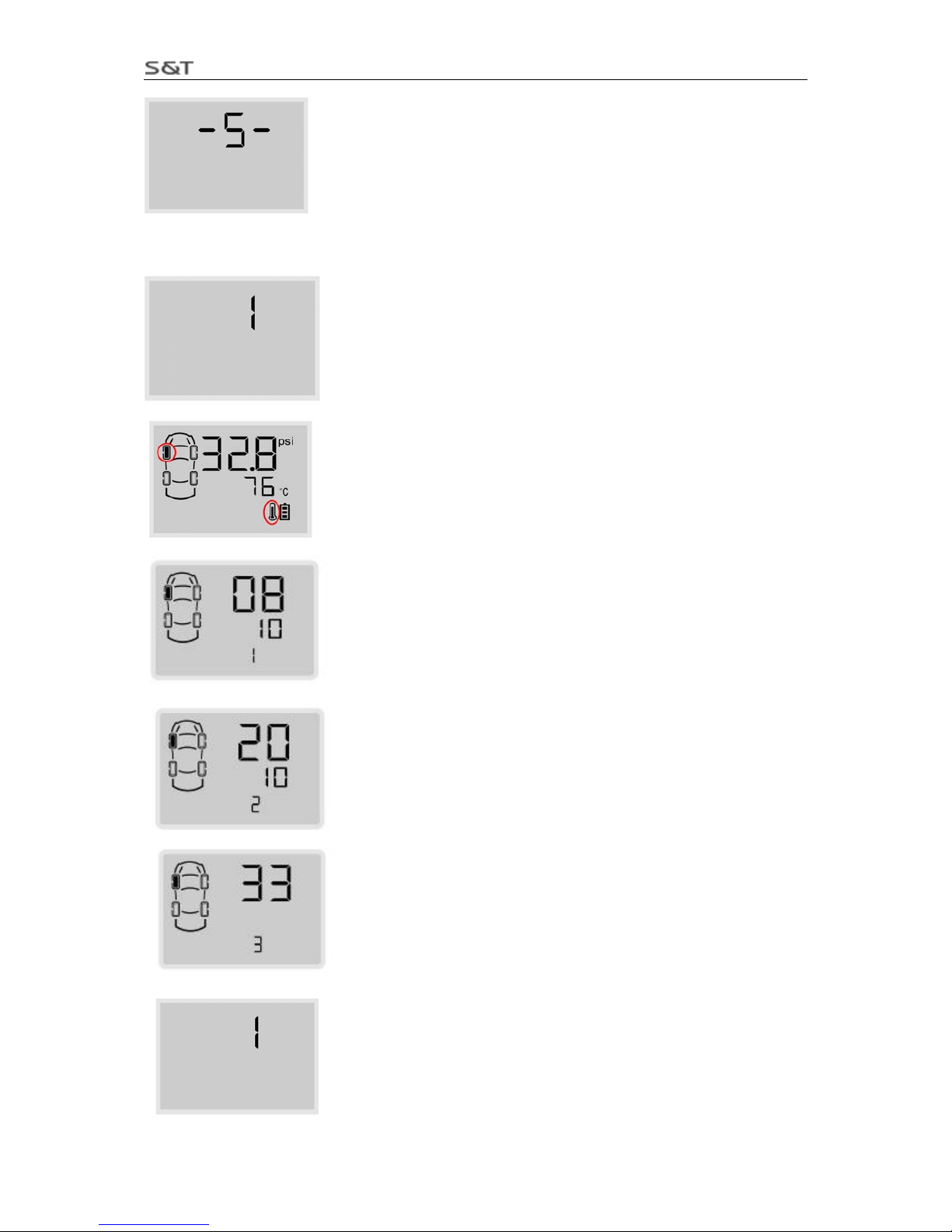
The 1” stands for first interface. The screen displays the year and month,
“08” stands for year 2008 and “10” stands for October. Press S key will go
through the year/ month/ date/ hour/ minute/ second in turn.
The “2” stands for second interface. The screen displays the date and hour,
“20” stands for date 20 and “10” stands for 10 am. Then time is 10 o’clock,
20th.
The “3” stands for third interface. The screen displays the minute and
second, “30” stands for 30 minutes and “50” stands for 50 seconds.
Press S key for a certain time to return to index interface 4.
Page 10
TPMS1209C01 User Manual
Page 10 of 23
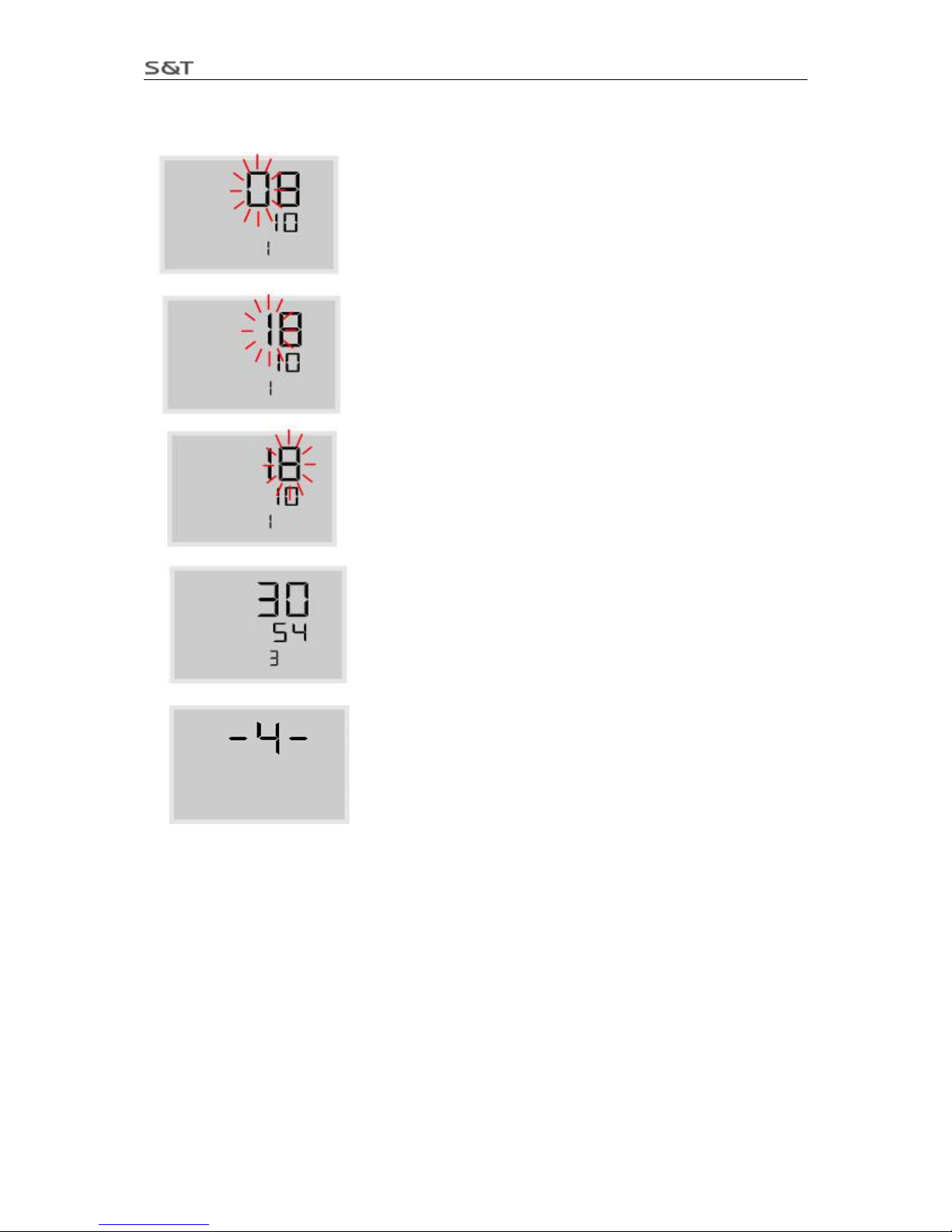
System time programming
Under any inquiry interface, press E key for 3 seconds to enter the
programming interface. As shown in below figure, under the year and
month inquiry interface, press E key for 3 seconds to enter the
programming interface, the digit “0” flashe
Press S key to adjust the value.
Press E key can switch to next digit.
After adjusted, press E key for 3 seconds to save with beep buzzes
twice and screen flashes twice, then return to the time inquiry interface.
During programming process, press and hold S key can return to the
index interface 4 and give up the change.
VI. Functions
Power Switch Automatically
The Monitor can be powered by the vehicle power through the lighter plug or the battery. Using vehicle
power is strongly recommended. If the lighter plug i s inserted into the power socket of the Monitor, even if
the battery group is also inside the Monitor battery box, the Monitor will still draw power from vehicle
power.
If power is not available from the lighter socket when the vehicle power is off, the system will
automatically switch to battery power. If the vehicle has no motion for more than 10 minutes when
powered by batteries, the Monitor will switch to the power-saving mode, screen will be off.
In the dormant state, once the monitor is vibrated, it will continue to work immediately.
Page 11

TPMS1209C01 User Manual
Page 11 of 23
Information Shown on the Screen
When the monitor is turned on, the screen displays the latest received
information, as shown in below figure (for front left tire, the pressure is 32.2
psi and the temperature is 26℃).
High Temperature Alarm
Function: The system will issue a High Temperature Alarm when the tire
temperature exceeds 75℃.
Alarm mode: The alarm light, LCD background light, high temperature
warning icon and the audible alarm turn on together.
Treatment: Press any key to stop the audible alarm or the audible alarm will automatically stop 30 seconds
later. The red alarm light remains on and the display reverts to the normal mode. The red alarm light goes
off only when the tire pressure returns to the standard level.
High Pressure Alarm
Function: The system will issue a high pressure alarm when the tire
pressure is 25% higher than the standard.
Alarm mode: The alarm light, LCD background light, high pressure
warning icon and the audible alarm turn on together.
Treatment: Press any key to stop the audible alarm or the audible alarm will
automatically stop 30 seconds later. The red alarm light remains on and the display reverts to the normal
mode. The red alarm light goes off only when the tire pressure returns to the standard level.
Low Pressure Level 1 Alarm
Function: The system will issue a low pressure level 1 alarm when the
tire pressure is 12.5% lower than the standard.
Alarm mode: The alarm light, LCD background light, low pressure level
1 warning icon and the audible alarm turn on together.
Treatment: Press any key to stop the audible alarm or the audible alarm will automatically stop 30 seconds
later. The red alarm light remains on and the display reverts to the normal mode. The red alarm light will
automatically turn off when the tire pressure returns to the standard level.
Page 12

TPMS1209C01 User Manual
Page 12 of 23
Low Pressure Level 2 Alarm
Function: The system will issue a low pressure level 2 alarm when the
tire pressure is 25% lower than the standard.
Alarm mode: The alarm light, LCD background light, low pressure level
2 warning icon and the audible alarm turn on together.
Treatment: Press any key to stop the audible alarm or the audible alarm will automatically stop 30 seconds
later. The red alarm light remains on and the display reverts to the normal mode. The red alarm light will
automatically turn off only when the tire pressure returns to the standard level.
Low Pressure Level 3 Alarm
Function: The system will issue a low pressure level 3 alarm when the
tire pressure is 50% lower than the standard.
Alarm mode: The alarm light, LCD background light, low pressure level
3 warning icon and the audible alarm turn on together.
Treatment: Press any key to stop the audible alarm or the audible alarm
will automatically stop 30 seconds later. The red alarm light remains on and the display reverts to the
normal mode. The red alarm light will automatically turn off when the tire pressure returns to the standard
level.
Quick Leaking Alarm
Function: The system will issue a quick leaking alarm when the pressure
drops more than 0.2 bar within 12 seconds.
Alarm Mode: The alarm light, LCD background light, the quick leaking
icon and the audible alarm turn on together.
Treatment: Press any key to stop the audible alarm. The system returns to display tire information in turn.
Note: When the system issues quick leaking alarm, user can only stop the
audible alarm by pressing any key. Once leakage is happened, please slow down to check the tire.
Transmitter Trouble Alarm
Function: If one Transmitter fails to work, or the Monitor can't receive
the data because of the RF interference for a certain time, the system will
issue a transmitter trouble alarm.
Alarm Mode: The red alarm light, LCD background light, the transmitter
trouble alarm icon and the audible alarm turn on together.
Treatment: Press any key to stop the audible alarm or the audible alarm will automatically stop 30 seconds
later. The red alarm light will automatically turn off when the monitor can receive the signals from this tire
position again.
Page 13
TPMS1209C01 User Manual
Page 13 of 23
Warning of Low Battery Power
Function: The system will issue a warning alarm when the battery power is
too low to afford the monitor to work.
Alarm mode: The beep buzzes twice shortly and stops, the battery icon
flashes continually.
Treatment: Replace the batteries or connect the monitor to the lighter plug immediately.
Alarm Record Inquiry
The monitor will issue an alarm when the tire is under the improper status. And the monitor will record the
alarm. User can inquire alarm record in this interface. The system can record the latest 10 alarms. When
there are 10 alarm records saved in monitor, the new alarm will be saved and the earliest alarm will be
deleted automatically.
Under the normal mode, press E key for 3 seconds to enter the monitor
programming interface, the screen display the index interface 1.
Press S key to switch to index interface 5, then press E key to enter the alarm
record inquiry interface.
Alarm Record Number
If there is no alarm record, the screen will display “- - -”
If there is alarm record, the latest one alarm will be displayed
.
Press S key to switch between alarm records. The system can record the
latest 10 alarms. Press S key to switch the alarm record number from 1 to
10.
Page 14
TPMS1209C01 User Manual
Page 14 of 23
Press S key for a certain time to return to the index interface 5.
Contents of Alarm Records
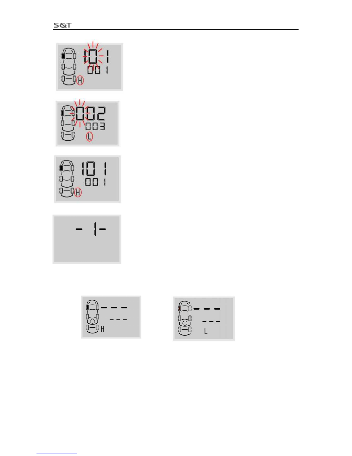
Under the alarm record inquiry interface, press E to check alarm details. As
shown in left figure, it is the first alarm record which is also the latest alarm
The first screen displays the detailed alarm information, as shown in left
figure, alarm happened to front left tire, the pressure is 32.8 psi, the
temperature is 76℃, the alarm is high temperature, as shown in the figure .
Press S key to check the detail alarm time. As shown in left figure, year
and month when alarm happened are displayed.
Press S key to inquire the time. As shown in left figure are date and hour.
Press S key to inquiry time. As shown in left figure is minute.
Under the inquiry interface, press E key to return to the alarm record
number interface.
Page 15

TPMS1209C01 User Manual
Page 15 of 23
Under the inquiry interface, press S key for 3 seconds to return to the index
interface 5.
VII. Pressure and Temperature Unit Inquiry and Programming
The system provides 3 kinds of pressure units Psi, bar and Kpa and 2 kinds of temperature units ℃ and
℉. User can choose the desired unit as following:
Under the normal mode, press E key for 3 seconds to enter the monitor
programming interface, the screen displays the index interface 1.
Press S key to switch to index interface 3, then press E key to enter the
pressure and temperature unit inquiry interface.
Pressure and temperature unit inquiry
The first interface displays pressure units. The unit with the “-“ is the current
pressure unit, as shown in left figure, the current pressure unit is psi.
Press S key to switch to the temperature unit inquiry, the temperature unit
with the “-“ is the current unit. As shown in left figure, the current
temperature unit is ℃.
Press S key for a certain time to return to the index interface 3.
Page 16

TPMS1209C01 User Manual
Page 16 of 23
Pressure Unit Programming
Under the pressure unit inquiry interface, press E key for 3 seconds to enter
the programming interface. The system current unit flashes. As shown in left
figure.
Press S key to switch the pressure unit among the psi, bar and kpa.
The current selected unit is KPa and it will flash. Press E key for 3 seconds
to save the selected unit with beep buzzes twice and screen flashes twice,
and then system return to pressure unit inquiry interface.
During programming process, Press S key for few seconds can return to the
index interface 3, no change will be saved to the system.
Temperature Unit Programming
Under the temperature inquiry interface, press E key for 3 seconds to enter
the programming interface. The current unit will flash.
Press S key to switch the temperature units between ℃ and ℉.
The current temperature unit is ℃, the unit flashes continually. Press E key
for 3 seconds to save the selected unit with two beeps and the screen
flashes twice, then returns to the temperature unit inquiry interface.
Page 17

TPMS1209C01 User Manual
Page 17 of 23
During programming process, Pressing the S key for few seconds will return
to the index interface 3, no change will be saved to the system.
VIII. New Transmitter Adding or Transmitter Replacement
Transmitter Replacement
If one of your transmitters is broken or lost, the user only needs to replace this one, the others will work as
normal.
Access the ID inquiry and programming interface, delete the broken or lost transmitter ID from the
monitor and program the new ID of transmitter.
New Transmitter Adding
If add new transmitter ID, such as ID of spare tire or ID of trailer tire, first access ID inquiry and
programming interface, program the ID in the corresponding tire position.
After deletion of a transmitter ID, new ID of the replacement transmitter has to be programmed into the
monitor. User can find the ID number from the package.
Inquiry and Programming of Transmitter ID
Under the normal mode, press E key for 3 seconds to enter the monitor
programming interface. The screen display “-1-” which stands for index
interface 1.
Under index interface 1, press E key to enter the transmitter ID programming
and inquiry interface.
Inquiry of ID
The first interface displays first six digits of transmitter ID of front left tire,
we also call the first 6 digits as “high part” of the ID number. The “H”
stands for the first six digits of the ID.
Page 18

TPMS1209C01 User Manual
Page 18 of 23
Press S key to switch screen interface. At this time, the screen display the
last six digits of transmitter ID, we also call it as “low part” of the ID
number. The “L” stands for the last six digits of the ID.
Press S key to go through each transmitter’s ID number.
Under any interface, press S key for few seconds to return to index
interface 1.
As shown in below 2 figures, there is no transmitter ID programmed into the tire position in solid black.
Programming of transmitter ID
Under the ID inquiry interface, press E key for 3 seconds to enter the ID
programming interface. At this time, the first digit flashes.
Press S key to adjust the value from 0 to 9.
Page 19
TPMS1209C01 User Manual
Page 19 of 23
Press E key to switch to next position to program, then the second digit
flashes.
When finish programming of the first 6 digits (High Part), press E key to
switch to last 6 digits (Low part) for programming, at this time, the first
digit also flashes.
When finish programming of all 12 digits, press E key for 3 seconds to
save the ID with beep buzzes twice and screen flashes twice, and then
return to ID inquiry interface.
During process of changing ID, press S key for few seconds to return to
index interface 1, and no change will be saved.
Note: When finished programming, but found desired change of ID is not saved. Please check as below for
possible wrong operation:
1. Programming of non-valid ID. The complete ID number of each transmitter has 12 digits, and is divided
into 4 groups. For each group the digit should be in the range of 1 to 255. For example, digit such as 0 or
256 cannot be set into monitor.
2. One same ID was set into two tire positions on monitor. Each transmitter has one unique ID, each tire
position on the monitor should be programmed with different ID number.
Page 20

TPMS1209C01 User Manual
Page 20 of 23
Installation of a New Transmitter
After programmed ID to the corresponding tire position in the monitor, user can install the transmitter to
the corresponding tires. For installation, please refer to “III. Installation of Transmitter”.
When installed successfully, user should check the standard pressure and system time on the monitor.
Please refer to “IV. Standard Pressure Inquiry and Programming” and “V. System Time Inquiry and
Programming”.
. Deletion of Transmitter IDⅨ
Firstly delete the broken or lost transmitter ID from the monitor.
Under the normal mode, press E key for 3 seconds to enter the monitor
programming interface, the screen displays index interface 1.
Press S key to switch to index interface 6, then press E key to enter the
transmitter ID deletion interface
.
The first display is first six transmitter ID number for front left tire. The
red tag “d” is an initial letter of delete which stands for transmitter ID
deletion interface to differentiate from the ID inquiry and programming
interface.
Press S key to switch to other different tires.
At any tire position, press E key for 3 seconds to delete the ID number
with beep buzzes twice and screen flashes twice, and then return to
inquiry interface.
Page 21

TPMS1209C01 User Manual
Page 21 of 23
The screen display “- - -” after delete the ID number. The tire position with
ID number deleted cannot be monitored under the normal mode. The screen
cannot display the tire’s pressure and temperature information.
Press S key to inquire the last 6 ID number of transmitter, the screen display
“- - -“which means the last 6 ID number are also deleted.
Press S key for 3 seconds to return to index interface 6.
Page 22

TPMS1209C01 User Manual
Page 22 of 23
X. Specifications
Operating Temperature of Monitor: -30℃~ +70℃
Operating Temperature of Transmitter: -30 +85℃℃
Pressure Monitoring Range of Transmitter: 0~6 bar / 0~87 psi
Pressure Monitoring Precision: ±0.1 bar/±1.5 psi
Modulation Type: FSK
Mid-Frequency: 433.9 Mhz
Transmitting Power: -10 dbm
Receiving Sensitivity: -105 dbm
Input Voltage: 5V(cigarette lighter adapter)
1.5V×2(AA batteries)
XI. Special Annex
1. LCD operating temperature
For all of the LCD, the lowest limitation operating temperature is -30℃, the upper temperature limit for
working mode is 70℃,for storage the temperature limit is 85℃. This is determined by the character of the
LCD. If the LCD works under lower temperature (for example, -30℃) for a long time, the LCD may be
destroyed.
In order to use the LCD properly, we strongly recommend the user power off the display if the temperature
inside the vehicle will be lower than -30℃ for a long time.
2. Checking and inflating the tire pressure regularly
In order to ensure that your tires remain at optimum pressure levels, it is strongly recommended that the
user check and adjust the pressure of each tire once a month.
3. How to change a new Transmitter
If one of the Transmitters is broken or the Transmitter fails to work, you should change a new Transmitter
for the tire. The broken Transmitter will not influence the other Transmitters’ operation, only the broken
one needs to be changed.
XII. Frequently Asked Questions
1. Q: Why is it necessary to do a periodic check on the pressure of a tire with TPMS?
A: As you drive, tires can be damaged or become unbalanced over time. Checking your tire on a
regular basis will ensure that it is functioning properly and safely.
2. Q: After installation, when changing the batteries or resetting the Monitor, the pressure information
doesn’t appear immediately.
A: Please wait for about 6 minutes. If nothing happens, reset the Monitor Display (turn it off and on)
and wait for another 6 minutes.
3. Q: Sometimes the LCD screen is not very clear.
A: This usually happens when the temperature inside the car is too low. When the temperature returns
to normal, the display will become clear again.
4. Q: Blurriness appears on the LCD screen, or there the LCD screen is blank. Sometimes the audible
alarm also can be heard.
A: This is usually caused by batteries of the Monitor Display being low on power. Change the
Page 23

TPMS1209C01 User Manual
Page 23 of 23
batteries or connect the Monitor Display to the vehicle power through a 12V Lighter Plug
immediately.
Q: Why does the pressure inside the tire rise after running for some time?
A: This is because of the friction between the tires and the ground. Heat from the friction of a moving
tire will cause pressure inside the tire to rise. The pressure inside a tire can fluctuate up or down
approximately 2-4psi depending on the speed of the vehicle. This is normal for most vehicles.
Q: Why is the Monitor Display not turning on?
A: If the Monitor Display is being powered by batteries, please check whether the batteries are
installed in the correct polarity and if batteries have enough power. If the Monitor is powered by the
12V Lighter Plug, please check the connection between the Lighter Plug and your TPMS unit.
XIII. W arranty Terms
Valid W arranty Card
1. The Warranty Card must be filled completely, signed by the user and
the authorized distributors of S&T TPMS.
2. The Warranty Card is valid in the countries or regions where the purchase occurs.
3. The W arranty Service requires user to offer the Warranty Card.
Warranty Condition, Responsibility and Limitation
1. The product warranty period is one year and is subject to the time marked on the invoice.
2. Any damage or faults due to improper use are not involved in the warranty commitment.
3. User is not allowed to open, repair and refit the products by themselves, otherwise the warranty service
will be invalid.
4. The warranty does not include replacement of the enclosure and display panel.
5. The warranty does not cover product damage due to abrasion and corrosion.
XIV. Important Notes
1. The Warranty Card must be filled completely and its number shall be quoted whenever the user requires
the service.
2. Please inform Sate in the case that the telephone number or address on the Warrant Card is changed.
3. The warranty responsibility is subject to the conditions and limitations specified in the User Manual.
FCC WARNING
This device complies with Part 15 of the FCC Rules. Operation is
subject to the following two conditions:
(1) this device may not cause harmful interference, and
(2) this device must accept any interference received, including interference that may cause
undesired operation.
NOTE: The manufacturer is not responsible for and radio or TV interference caused by
unauthorized modifications to this equipment. Such modifications could void the user’s authority
to operate the equipment.
 Loading...