

ST TDE1767, TDE1787 User Manual
Interface circuit (relay and Lamp-driver)
Features
■ Open ground protection
■ High output current
■ Adjustable short-circuit protection
■ Internal thermal protection with external reset
■ Large supply voltage range
■ Alarm output
■ Input voltage can be higher than V
■
Output voltage can be lower than ground
(V
- VO ≤ V
CC
CC[max]
)
Description
CC
TDE1767
TDE1787
DIP-8
The TDE1767, TDE1767A, TDE1787, TDE1787A
are a monolithic amplifiers designed for high
current and high voltage applications, specifically
to drive lamps, relays, stepping motors.
The devices are assentially blow-out proof. The
output is prois protected from short-circuits with
the positive supply or drive. In addition thermal
shut down is provited to keep the IC from
overheathing.
If internal dissipation becomes too high, the driver
will shut down to prevent excessive heating. The
output stays null after the overheating is off, if the
reset input is low. If high the output will
alternatively switch-on and off until the overload is
removed.
Table 1. Device summary
Part number Package Packaging
TDE1767DP DIP8 Tube
TDE1767ADP DIP8 Tube
The devices operates over a wide range voltages
from standard 15V operational amplifier supplies
to the single +6V or +48V used for industrial
electric systems. Input voltages can be higher
than in the V
CC
.
An alarm output suitable for driving a LED is
provited. This LED, normally on (if referred to
ground), will die out or flash during an overload
depending on the state of the reset input.
The output is low in open ground conditions.
TDE1787DP DIP8 Tube
TDE1787ADP DIP8 Tube
March 2007 Rev 2 1/16
www.st.com
16

Contents TDE1767 - TDE1787
Contents
1 Pin connections . . . . . . . . . . . . . . . . . . . . . . . . . . . . . . . . . . . . . . . . . . . . . 3
2 Maximum ratings . . . . . . . . . . . . . . . . . . . . . . . . . . . . . . . . . . . . . . . . . . . . 3
2.1 Absolute maximum ratings . . . . . . . . . . . . . . . . . . . . . . . . . . . . . . . . . . . . . 3
2.2 Thermal data . . . . . . . . . . . . . . . . . . . . . . . . . . . . . . . . . . . . . . . . . . . . . . . 3
3 Electrical characteristcs . . . . . . . . . . . . . . . . . . . . . . . . . . . . . . . . . . . . . . 4
4 Schematic diagrams . . . . . . . . . . . . . . . . . . . . . . . . . . . . . . . . . . . . . . . . . 6
5 Typical characteristics . . . . . . . . . . . . . . . . . . . . . . . . . . . . . . . . . . . . . . . 7
6 Typical application . . . . . . . . . . . . . . . . . . . . . . . . . . . . . . . . . . . . . . . . . . 9
7 Using alarm output . . . . . . . . . . . . . . . . . . . . . . . . . . . . . . . . . . . . . . . . . 11
8 Mechanical data . . . . . . . . . . . . . . . . . . . . . . . . . . . . . . . . . . . . . . . . . . . . 13
9 Revision history . . . . . . . . . . . . . . . . . . . . . . . . . . . . . . . . . . . . . . . . . . . 15
2/16

TDE1767 - TDE1787 Pin connections
1 Pin connections
Figure 1. Pin connection (top view)
ALARM OUTPUT
INVERTING INPUT
NON INVERTING INPUT
GND
2 Maximum ratings
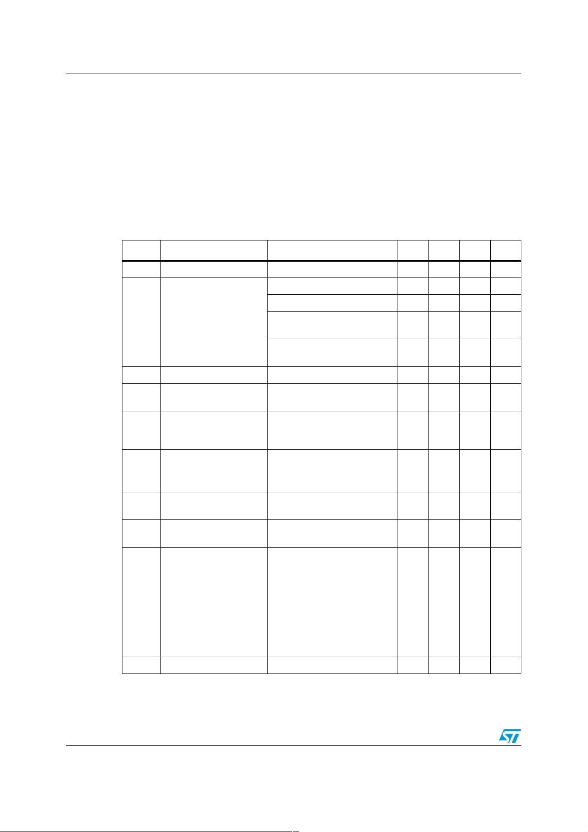
2.1 Absolute maximum ratings
Table 2. Absolute maximum ratings
Symbol Parameter
VCC Supply voltage 60 50 V
V
V
l(reset)
I
P
T
oper
T
Input differential voltage 60 50 V
ID
V
Input voltage - 10 to + 60 - 10 to + 50 V
l
Output current 1.3 1.2 A
I
O
Reset input voltage - 0.5 to + 60 - 0.5 to + 50 V
Alarm output current - 10 to + 20 - 10 to + 20 mA
OA
Power dissipation Internally Limited mW
tot
Operating ambient temperature
range
Storage temperature range - 65 to + 150 - 65 to + 150 °C
stg
1
2
3
4 RESET
D03IN1475
TDE1767A
TDE1787A
CURRENT LIMIT8
V
7
CC
OUTPUT
6
5
TDE1767
TDE1787
- 25 to + 85 - 25 to + 85 °C
Unit
2.2 Thermal data
Table 3. Thermal data
Symbol Parameter Value Unit
R
th(JC)
R
th(JA)
Note: Devices bonded on a 40 cm2 glass-epoxy printed circuit 0.15 cm thick with 4 cm2 of copper.
Thermal resistance junction-case max 30 °C/W
Thermal resistance junction-ambient max 80 °C/W
3/16
Electrical characteristcs TDE1767 - TDE1787
3 Electrical characteristcs
TDE1767A: - 25°C ≤ TA ≤ 85°C, 6V ≤ VCC ≤ 55V, Io ≤ 500mA, TJ ≤ 150°C
TDE1767: - 25°C ≤ T
TDE1787A: - 25°C ≤ T
TDE1787: 25°C ≤ T
≤ 85°C, 6V ≤ VCC ≤ 45V, Io ≤ 500mA, TJ ≤ 150°C
A
≤ 85°C, 6V ≤ VCC ≤ 55V, Io ≤ 300mA, TJ ≤ 150°C
A
≤ 85°C, 6V ≤ VCC ≤ 45V, Io ≤ 300mA, TJ ≤ 150°C
A
Unless otherwise specified.
Table 4. Electrical characteristics
Symbol Parameter Test condition Min. Typ. Max. Unit
V
Input offset voltage (note 1) 2 50 mV
IO
(measured on pin 4)
= 25°C) 5.8 8 mA
A
CCmax
CCmax
, (TJ = 150°C)
, (TA = 25°C)
57mA
1.5 4 mA
1
1
1
1
= 0.22Ω
SC
= 0.33Ω
SC
700
380
60
45
60
45
mA
mA
V
V
Output high (T
Power supply current
I
CC
Output high
(V
= V
CC
Output low
(V
= V
CC
Imput bias current 15 100 µA
I
IB
Common-mode input
CM
voltage range
V
Input voltage range
I
TDE1787A, TDE1767A
TDE1787, TDE1767
Vref
≥ 1V (figure1, note2)
TDE1787A, TDE1767A
TDE1787, TDE1767
= 35V, t = 10ms
V
Short circuit output
I
SC
current
Output limit sense
sense
voltage
CC
TDE1767A: R
TDE1787A: R
V
= VCC -2V, t = 10ms 130 150 170 mV
O
V
V
V
V
V
Output limit sense
sense
voltage
= 0V, t = 10ms 120 140 165 mV
V
O
Output high V
= 0; VCC = 30V
R
SC
TDE1787A, TDE1767A:
TJ = 25°C
V
O(sat)
Output saturation voltage
TDE1787, TDE1767: T
TDE1787A, TDE1767A:
= 150°C
T
J
TDE1787, TDE1767:
= 150°C
T
J
Output leakage current Output low 100 µA
I
OL
4/16
+
- V
I
-
≥ 50mV;
I
= 25°C
J
1
1
1.1
1.1
1.1
1.2
1.2
1.3
V
V
V
V

TDE1767 - TDE1787 Electrical characteristcs
Table 4. Electrical characteristics (continued)
Symbol Parameter Test condition Min. Typ. Max. Unit
I
I
reset
V
th-reset
Output source current
= VCC-2.5V
V
Available alarm output
A
current
AH
Output sink current
(in thermal shut-down)
= 1.4V
V
A
Reset input current 2 40 µA
Reset threhold 1.4 A
-4 -5 mA
510 mA
Output leakage current open ground 10 µA
Note: 1 The offset voltage given is the maximum value of different input voltage reguired to drive the
output voltage whitin 2 V of the ground or the supply voltage.
2 Input voltage range is indipendent of the supply voltage.
5/16
 Loading...