

Aerospace 1 x 20 and 2 x 20 A - 100 V Schottky rectifier
Features
■ Forward current: 1 x 20 and 2 x 20 A
■ Repetitive peak voltage: 100 V
■ Low forward voltage drop: 0.8 V
■ Maximum junction temperature: 175 °C
■ Negligible switching losses
■ Low capacitance
■ High reverse avalanche surge capability
■ Hermetic packages
■ Target radiation qualification:
– 150 krad (Si) low dose rate
– 1 Mrad high dose rate
■ ESCC qualified
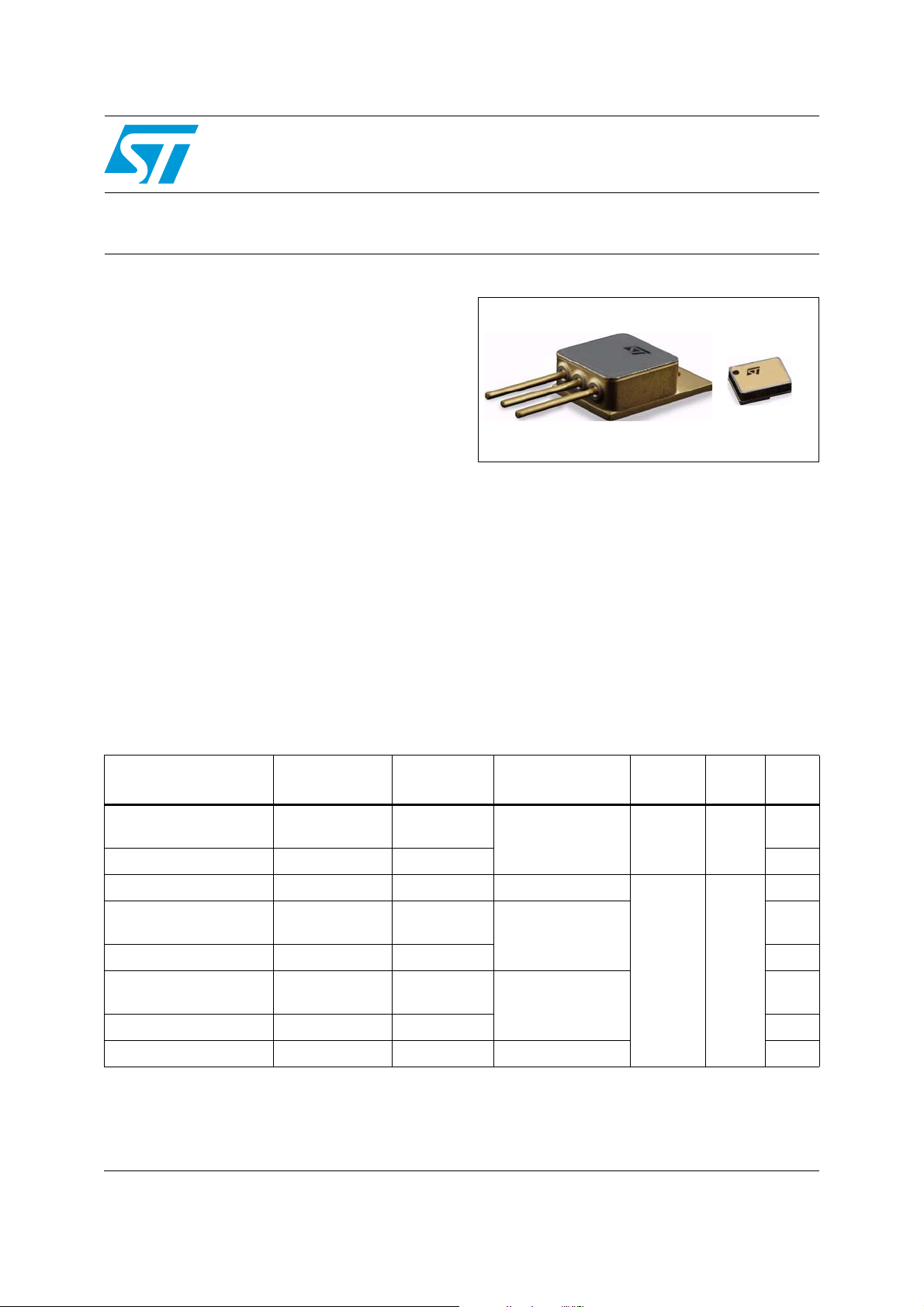
STPS20100HR
TO-254
Description
This power Schottky rectifier is designed and
packaged to comply with the ESCC5000
specification for aerospace products. Housed in
hermetically sealed packages both surface mount
and through hole, it is ideal for use in applications
for aerospace and other harsh environments.
SMD.5
The STPS20100HR is intended for use in medium
voltage application and particularly, in high
frequency circuits where low switching losses and
low noise are required.
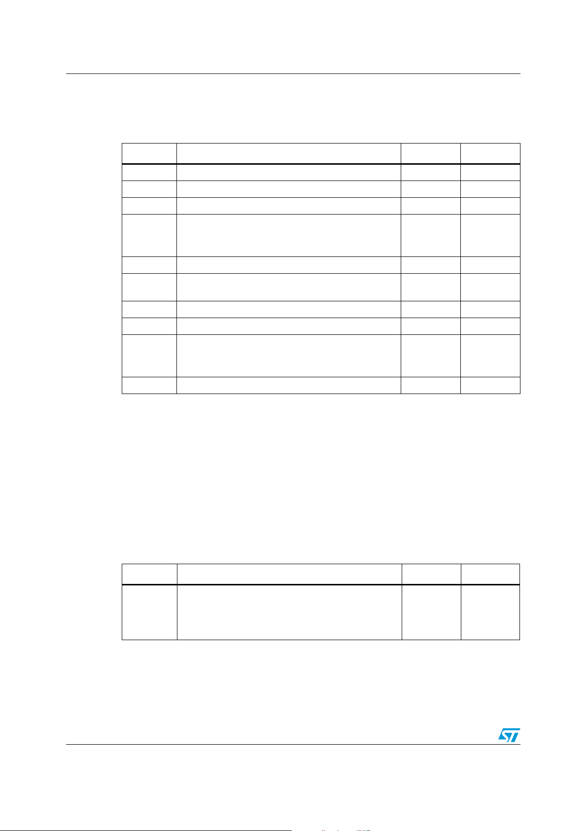
Table 1. Device summary
Order code
STPS20100S1 -
STPS20100SHRB 5106/016/05 ESCC flight -
STPS20100FSYHRB 5106/016/01 ESCC flight Single die
STPS20100AFSY1 -
STPS20100AFSYHRB 5106/016/02 ESCC flight Y
STPS20100CFSY1 -
STPS20100CFSYHRB 5106/016/03 ESCC flight Y
STPS20100SFSYHRB 5106/016/04 ESCC flight Double die, serial Y
ESCC detailed
specification
Quality level Configuration Package Mass EPPL
Engineering
model
Engineering
model
Engineering
model
Single die SMD.5 2.0 g
Double die,
common anode
TO-254 10.0 g
Double die,
common cathode
-
-
-
-
March 2010 Doc ID 16953 Rev 1 1/10
www.st.com
10
Characteristics STPS20100HR
1 Characteristics
Table 2. Absolute maximum ratings
Symbol Characteristic Value Unit
(6)
(6)
(3)
(2)
(1)
(4), (5)
250 A
100 V
1A
20
A
40
-65 to +175 °C
-65 to +175 °C
+260
oC
+245
I
FSM
V
RRM
I
RRM
I
O
I
F(RMS)
T
OP
T
T
STG
T
SOL
Forward surge current (per diode)
Repetitive peak reverse voltage
Repetitive peak reverse current
Average output rectified current (50% duty cycle):
All variants (per diode)
Variants 02, and 03 (per device)
Forward rms current (per diode) 30 A
Operating temperature range
(case temperature)
Junction temperature +175 °C
J
Storage temperature range
Soldering temperature:
For TO-254
For SMD.5
(7)
(8)
dV/dt Critical rate of rise of reverse voltage 10000 V/µs
1. Sinusoidal pulse of 10 ms duration
2. Pulsed, duration 5 ms, F = 50 Hz
3. Pulsed, duration 2 µs, F = 1 kHz
4. For T
5. The “per Device” ratings apply only as follows:
Variant 02: when both cathode terminals are tied together
Variant 03: when both anode terminals are tied together.
6. For variants with hot solder dip lead finish all testing performed at T
inert atmosphere.
7. Duration 10 seconds maximum at a distance of not less than 1.5 mm from the device body and the same
lead shall not be resoldered until 3 minutes have elapsed.
8. Duration 5 seconds maximum and the same package shall not be resoldered until 3 minutes have elapsed.
Table 3. Thermal resistance
> +140 °C, derate linearly to 0 A at +175 °C.
case
> +125 °C are carried out in a 100%
amb
Symbol Characteristic Value Unit
Thermal resistance, junction to case
th(j-c)
1. Package mounted on infinite heatsink
2. The per device ratings apply for variant 02 when both cathode terminals are tied together and for variant 03
when when both anode terminals are tied togther.
Variants 02, 03 and 04 (per diode)
Variants 02, and 03 (per device)
(2)
Variants 01, and 05
(1)
R
1.65
1.65
0.85
°C/W
2/10 Doc ID 16953 Rev 1
STPS20100HR Characteristics
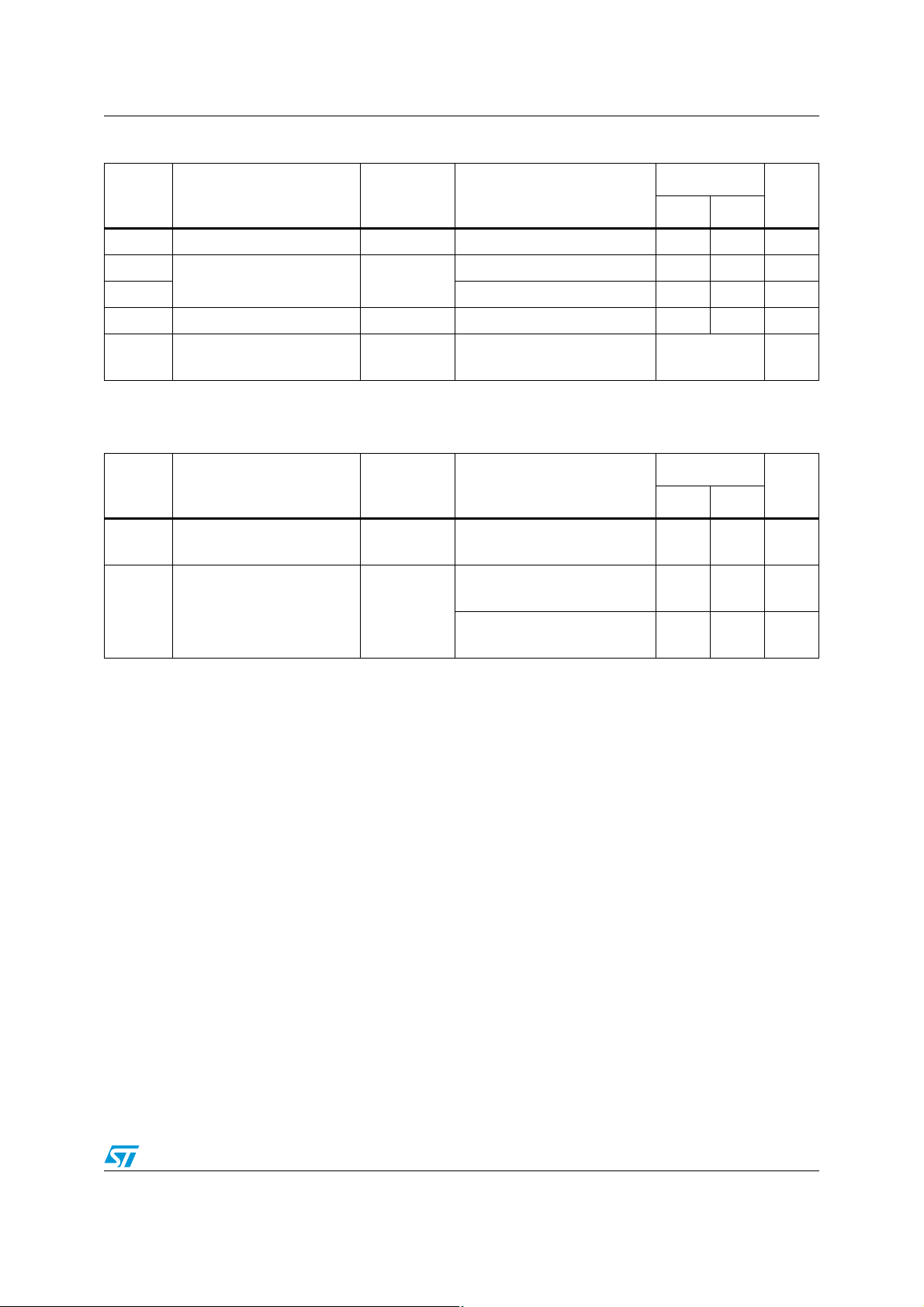
Table 4. Electrical measurements at ambiant temperature (per diode), T
Symbol Characteristic
I
R
(1)
V
F1
(1)
V
F2
C Capacitance 4001 V
Z
th(j-c)
1. Pulse width ≤ 680µs, Duty Cycle ≤ 2%
Table 5. Electrical measurements at high and low temperatures (per diode)
Symbol Characteristic
I
R
(1)
V
F2
1. Pulse width ≤ 680µs, Duty Cycle ≤ 2%
s
MIL-STD-750
test method
Test conditions
amb
Reverse Current 4016 DC method, VR = 100 V - 30 µA
Forward Voltage 4011
Pulse method, I
= 10 A - 780 mV
F
Pulse method, IF = 20 A - 1 V
= 10 V, F = 1 MHz - 700 pF
R
= 15 to 40 A, tH = 50 ms
Relative thermal impedance,
junction to case
3101
MIL-STD-750
test method
Reverse Current 4016
Forward Voltage 4011
I
H
= 50 mA, tmd = 100 µs
I
M
Test conditions
T
= +125 (+0, -5) °C
case
DC method, V
T
= +125 (+0, -5) °C
case
pulse method, I
T
= -55 (+5, -0) °C
case
pulse method, I
= 100 V
R
= 20 A
F
= 20 A
F
= 22 ±3 °C
Values
Units
Min. Max.
Calculate ΔV
Values
Min. Max.
-20mA
-900mV
-1.1V
°C/W
F
Units
Doc ID 16953 Rev 1 3/10
 Loading...