

ST STPS16H100CG, STPS16H100CFP, STPS16H100CR User Manual
查询STPS16H100C供应商
®
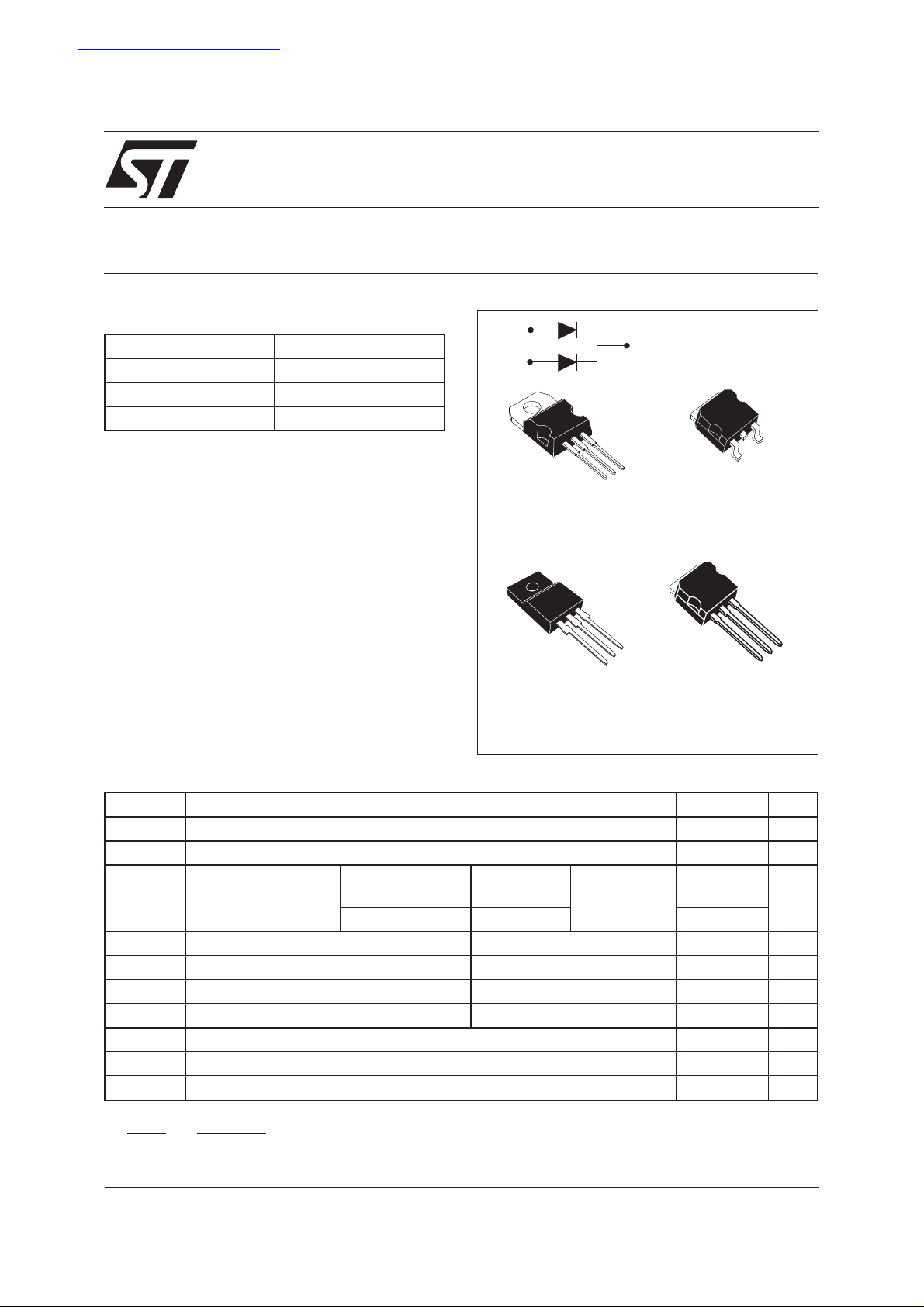
STPS16H100CT/CG/CFP/CR
HIGH VOLTAGE POWER SCHOTTKY RECTIFIER
MAIN PRODUCT CHARACTERISTICS
I
F(AV)
V
RRM
Tj (max) 175 °C
V
(max) 0.64V
F
FEATURES AND BENEFITS
NEGLIGIBLE SWITCHING LOSSES
■
HIGH JUNCTION TEMPERATURE CAPABILITY
■
LOW LEAKAGE CURRENT
■
GOOD TRADE OFF BETWEEN LEAKAGE
■
CURRENT AND FORWARD VOLTAGE DROP
■ AVALANCHE CAPABILITY SPECIFIED
DESCRIPTION
DualcentertapSchottkyrectifierdesignedfor
high frequency miniature Switch Mode Power
Supplies such as adaptators and on board
DC/DC converters.
2x8A
100 V
A1
A2
K
A1
TO-220AB
STPS16H100CT
K
A1
TO-220FPAB
STPS16H100CFP
A2
A2
K
STPS16H100CG
STPS16H100CR
K
D2PAK
I2PAK
A1
A1
A2
A2
K
ABSOLUTE RATINGS (limiting values, per diode)
Symbol Parameter Value Unit
V
RRM
I
F(RMS)
I
F(AV)
Repetitive peak reverse voltage 100 V
RMS forward current 30 A
Average forward
current δ = 0.5
TO-220AB
D2PAK/I2PAK
Tc = 165°C Per diode 8 A
TO-220FPAB Tc = 150°C Per device 16
I
I
I
P
T
FSM
RRM
RSM
ARM
stg
Surge non repetitive forward current tp = 10 ms sinusoidal 200 A
Repetitive peak reverse current tp=2µssquare F = 1kHz 1 A
Non repetitive peak reverse current tp = 100 µs square 2 A
Repetitive peak avalanche power tp= 1µs Tj = 25°C 8700 W
Storage temperature range -65 to+175 °C
Tj Maximum operating junction temperature * 175 °C
dV/dt Critical rate of rise of reverse voltage 10000 V/µs
dPtot
* :
<
dTj Rth j a
July 2003 - Ed: 2A
thermal runaway condition for a diode on its own heatsink
−1()
1/7
STPS16H100CT/CG/CFP/CR
THERMAL RESISTANCES
Symbol Parameter Value Unit
R
th (j-c)
R
th (c)
When the diodes 1 and 2 are used simultaneously :
∆ Tj(diode 1) = P(diode1) x R
STATIC ELECTRICAL CHARACTERISTICS (per diode)
Symbol Parameter Tests Conditions Min. Typ. Max. Unit
I
R
V
Junction to ambient TO-220AB / D2PAK/I2PAK Per diode 1.6 °C/W
TO-220FPAB 4
TO-220AB / D
2
PAK/I2PAK Total 1.1 °C/W
TO-220FPAB 3.5
TO-220AB / D2PAK/I2PAK
Coupling
0.6 °C/W
TO-220FPAB 3
(Per diode) + P(diode 2) x R
th(j-c)
* Reverse leakage Current Tj = 25°C VR=V
th(c)
RRM
3.6 µA
Tj = 125°C 1.6 5 mA
** Forward Voltage drop Tj = 25°C IF= 8 A 0.77 V
F
Tj = 125°CI
Tj = 25°C I
Tj = 125°C I
= 8 A 0.59 0.64
F
= 16 A 0.88
F
= 16 A 0.67 0.73
F
Pulse test : * tp=5ms,δ<2%
** tp = 380 µs, δ <2%
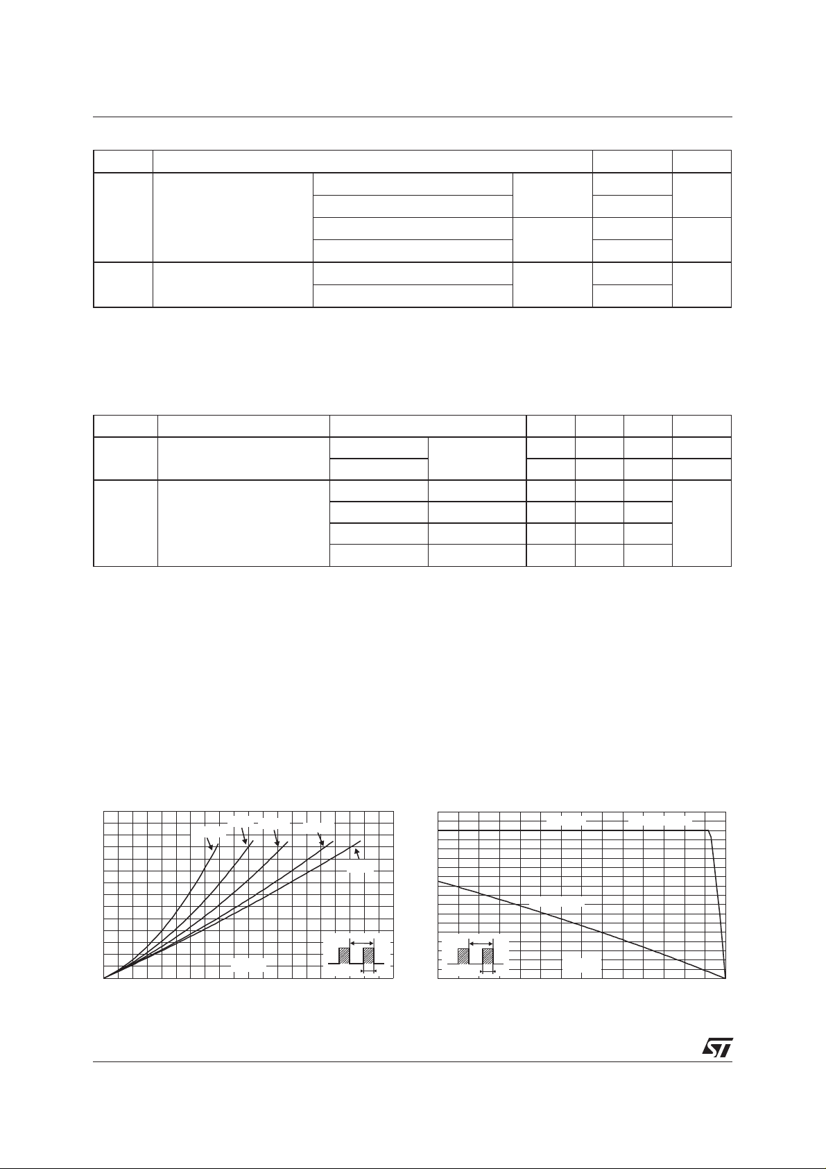
To evaluate the conduction losses use the following equation :
P = 0.55 x I
Fig.1: Conductionlossesversus average current.
F(AV)
+ 0.011 x I
F2(RMS)
Fig. 2: Average forward current versus ambient
temperature (δ=0.5).
P (W)F(AV)
7
6
5
4
3
2
1
0
012345678910
δ = 0.05
δ = 0.1
I (A)F(AV)
δ = 0.2
δ = 0.5
δ
=tp/T
δ = 1
T
tp
I (A)F(AV)
9
8
7
6
5
4
3
2
1
=tp/T
δ
0
0 25 50 75 100 125 150 175
Rth
=Rth
(j-a)
(j-c)
Rth
=50°C/W
(j-a)
T
tp
T (°C)amb
TO-220AB/D²PAK/I²PAK
2/7
STPS16H100CT/CG/CFP/CR
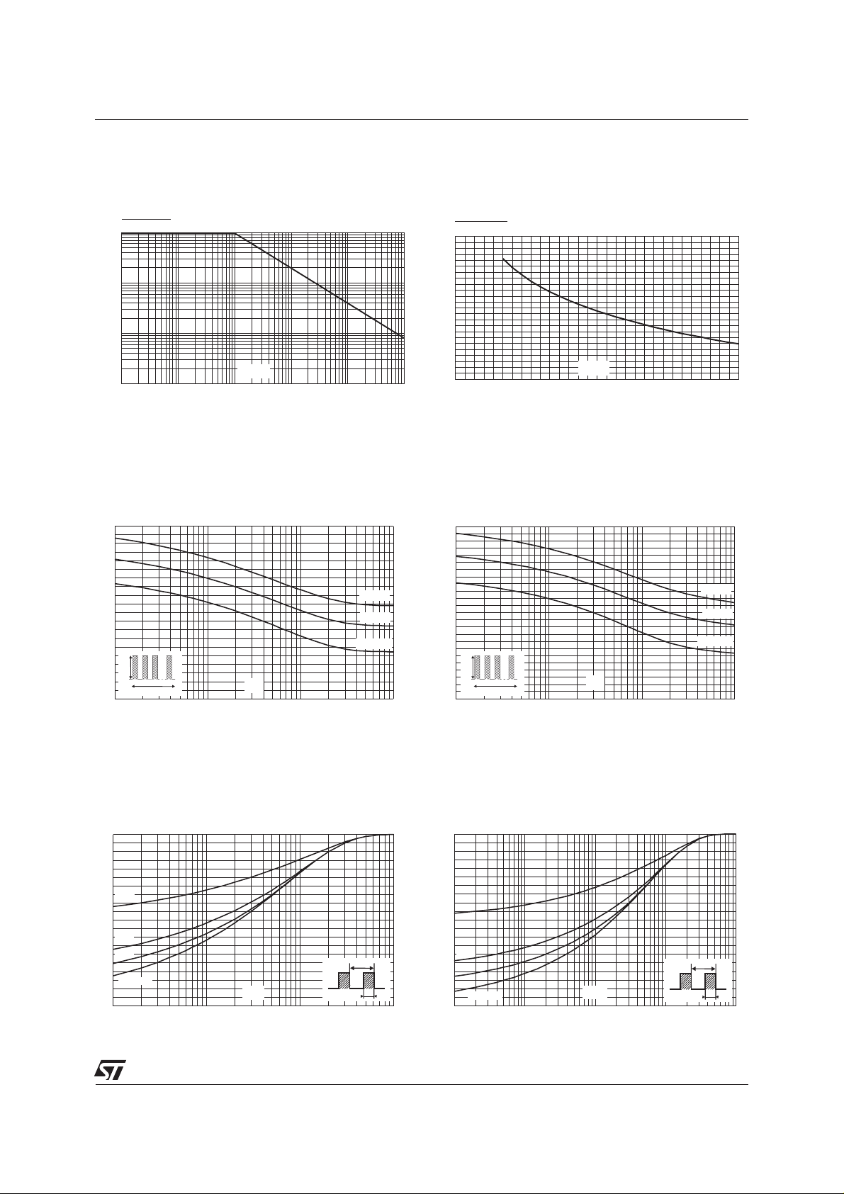
Fig. 3: Normalized avalanche power derating
versus pulse duration.
P(t)
ARM p
P (1µs)
ARM
1
0.1
0.01
t (µs)
0.001
0.10.01 1
p
10 100 1000
Fig. 5-1: Non repetitive surge peak forward current
versus overload duration (maximum values)
(TO-220AB, D²PAK, I²PAK).
I (A)M
200
180
160
140
120
100
80
60
40
IM
20
0
1.E-03 1.E-02 1.E-01 1.E+00
δ=0.5
t
t(s)
TC=25°C
TC=75°C
TC=125°C
Fig. 4: Normalized avalanche power derating
versus junction temperature.
P(t)
ARM p
P (25°C)
ARM
1.2
1
0.8
0.6
0.4
0.2
T (°C)
0
j
0 25 50 75 100 125 150
Fig. 5-2: Non repetitive surge peak forward current
versus overload duration (maximum values)
(TO-220FPAB).
I (A)M
120
110
100
90
80
70
60
50
40
30
IM
20
10
0
1.E-03 1.E-02 1.E-01 1.E+00
δ=0.5
t
t(s)
TC=25°C
TC=75°C
TC=125°C
Fig. 6-1: Relative variation of thermal impedance
junction to case versus pulse duration (TO-220AB,
D²PAK & I²PAK).
Zth(j-c) / Rth(j-c)
1.0
0.9
0.8
0.7
δ = 0.5
0.6
0.5
0.4
δ = 0.2
δ = 0.1
0.3
0.2
Single pulse
0.1
0.0
1.E-03 1.E-02 1.E-01 1.E+00
t (s)P
δ
=tp/T
T
tp
Fig. 6-2: Relative variation of thermal impedance
junctionto case versus pulse duration (TO-220FPAB).
Zth(j-c) / Rth(j-c)
1.0
0.9
0.8
0.7
0.6
δ = 0.5
0.5
0.4
δ = 0.2
0.3
δ = 0.1
0.2
0.1
Single pulse
0.0
1.E-03 1.E-02 1.E-01 1.E+00 1.E+01
t (s)P
δ
=tp/T
T
tp
3/7
 Loading...