

ST STM706T, STM706S, STM706R, STM706P, STM708T User Manual
...
Features
STM706T/S/R, STM706P, STM708T/S/R
3 V supervisor
■ Precision V
monitor
CC
– STM706/708
T: 3.00 V
S: 2.88 V
R: STM706P: 2.59 V
■ RST and RST outputs
■ 200 ms (typ.) t
Watchdog timer - 1.6 s (typ.)
■
■ Manual reset input (MR)
■ Power-fail comparator (PFI/PFO)
■ Low supply current - 40 µA (typ.)
■ Guaranteed RST (RST) assertion down to
V
= 1.0 V
CC
■ Operating temperature: –40 °C to 85 °C
≤
≤
V
V
rec
RST
RST
≤
≤
3.15 V
3.00 V
≤
V
RST
≤
2.70 V
(industrial grade)
■ RoHS compliance
– Lead-free components are compliant with
the RoHS directive
Table 1. Device summary
8
1
SO8 (M)
TSSOP8 3x3 (DS)
1. Contact local ST sales office for availability.
(1)
Watchdog
input
Watchdog
output
(1)
Active-low
(1)
RST
Active-high
(1)
RST
Manual
reset input
Power-fail
comparator
STM706T/S/R ✓✓ ✓ ✓ ✓
STM706P
(2)
✓✓ ✓ ✓ ✓
STM708T/S/R ✓✓✓✓
1. Push-pull output.
2. The STM706P is identical to the STM706R, except its reset output is active-high.
September 2011 Doc ID 10518 Rev 11 1/32
www.st.com
1

Contents STM706T/S/R, STM706P, STM708T/S/R
Contents
1 Description . . . . . . . . . . . . . . . . . . . . . . . . . . . . . . . . . . . . . . . . . . . . . . . . . 5
2 Pin descriptions . . . . . . . . . . . . . . . . . . . . . . . . . . . . . . . . . . . . . . . . . . . . 8
2.1 MR . . . . . . . . . . . . . . . . . . . . . . . . . . . . . . . . . . . . . . . . . . . . . . . . . . . . . . . 8
2.2 WDI . . . . . . . . . . . . . . . . . . . . . . . . . . . . . . . . . . . . . . . . . . . . . . . . . . . . . . 8
2.3 WDO
2.4 RST
2.5 RST . . . . . . . . . . . . . . . . . . . . . . . . . . . . . . . . . . . . . . . . . . . . . . . . . . . . . . 8
2.6 PFI . . . . . . . . . . . . . . . . . . . . . . . . . . . . . . . . . . . . . . . . . . . . . . . . . . . . . . . 8
2.7 PFO
. . . . . . . . . . . . . . . . . . . . . . . . . . . . . . . . . . . . . . . . . . . . . . . . . . . . . . 8
. . . . . . . . . . . . . . . . . . . . . . . . . . . . . . . . . . . . . . . . . . . . . . . . . . . . . . 8
. . . . . . . . . . . . . . . . . . . . . . . . . . . . . . . . . . . . . . . . . . . . . . . . . . . . . . 9
3 Operation . . . . . . . . . . . . . . . . . . . . . . . . . . . . . . . . . . . . . . . . . . . . . . . . . 11
3.1 Reset output . . . . . . . . . . . . . . . . . . . . . . . . . . . . . . . . . . . . . . . . . . . . . . . 11
3.2 Push-button reset input . . . . . . . . . . . . . . . . . . . . . . . . . . . . . . . . . . . . . . 11
3.3 Watchdog input (STM706T/S/R and STM706P) . . . . . . . . . . . . . . . . . . . 11
3.4 Watchdog output (STM706T/S/R and STM706P) . . . . . . . . . . . . . . . . . . 11
3.5 Power-fail input/output . . . . . . . . . . . . . . . . . . . . . . . . . . . . . . . . . . . . . . . 12
3.6 Ensuring a valid reset output down to V
3.7 Interfacing to microprocessors with bi-directional reset pins . . . . . . . . . . 13
= 0 V . . . . . . . . . . . . . . . . . . . 12
CC
4 Typical operating characteristics . . . . . . . . . . . . . . . . . . . . . . . . . . . . . 14
5 Maximum ratings . . . . . . . . . . . . . . . . . . . . . . . . . . . . . . . . . . . . . . . . . . . 21
6 DC and AC parameters . . . . . . . . . . . . . . . . . . . . . . . . . . . . . . . . . . . . . . 22
7 Package mechanical data . . . . . . . . . . . . . . . . . . . . . . . . . . . . . . . . . . . . 26
8 Part numbering . . . . . . . . . . . . . . . . . . . . . . . . . . . . . . . . . . . . . . . . . . . . 29
9 Revision history . . . . . . . . . . . . . . . . . . . . . . . . . . . . . . . . . . . . . . . . . . . 31
2/32 Doc ID 10518 Rev 11

STM706T/S/R, STM706P, STM708T/S/R List of tables
List of tables
Table 1. Device summary. . . . . . . . . . . . . . . . . . . . . . . . . . . . . . . . . . . . . . . . . . . . . . . . . . . . . . . . . . 1
Table 2. Signal names . . . . . . . . . . . . . . . . . . . . . . . . . . . . . . . . . . . . . . . . . . . . . . . . . . . . . . . . . . . . 6
Table 3. Pin description . . . . . . . . . . . . . . . . . . . . . . . . . . . . . . . . . . . . . . . . . . . . . . . . . . . . . . . . . . . 9
Table 4. Absolute maximum ratings . . . . . . . . . . . . . . . . . . . . . . . . . . . . . . . . . . . . . . . . . . . . . . . . . 21
Table 5. Operating and AC measurement conditions . . . . . . . . . . . . . . . . . . . . . . . . . . . . . . . . . . . . 22
Table 6. DC and AC characteristics . . . . . . . . . . . . . . . . . . . . . . . . . . . . . . . . . . . . . . . . . . . . . . . . . 24
Table 7. SO8 - 8-lead plastic small outline, 150 mils body width,
package mechanical data. . . . . . . . . . . . . . . . . . . . . . . . . . . . . . . . . . . . . . . . . . . . . . . . . . 27
Table 8. TSSOP8 - 8-lead, thin shrink small outline, 3 x 3 mm body size,
mechanical data . . . . . . . . . . . . . . . . . . . . . . . . . . . . . . . . . . . . . . . . . . . . . . . . . . . . . . . . . 28
Table 9. Ordering information scheme . . . . . . . . . . . . . . . . . . . . . . . . . . . . . . . . . . . . . . . . . . . . . . . 29
Table 10. Marking description. . . . . . . . . . . . . . . . . . . . . . . . . . . . . . . . . . . . . . . . . . . . . . . . . . . . . . . 30
Table 11. Document revision history . . . . . . . . . . . . . . . . . . . . . . . . . . . . . . . . . . . . . . . . . . . . . . . . . 31
Doc ID 10518 Rev 11 3/32

List of figures STM706T/S/R, STM706P, STM708T/S/R
List of figures
Figure 1. Logic diagram (STM706T/S/R and STM706P) . . . . . . . . . . . . . . . . . . . . . . . . . . . . . . . . . . . 5
Figure 2. Logic diagram (STM708T/S/R) . . . . . . . . . . . . . . . . . . . . . . . . . . . . . . . . . . . . . . . . . . . . . . . 5
Figure 3. STM706T/S/R and STM706P SO8 connections. . . . . . . . . . . . . . . . . . . . . . . . . . . . . . . . . . 6
Figure 4. STM706T/S/R and STM706P TSSOP8 connections . . . . . . . . . . . . . . . . . . . . . . . . . . . . . . 6
Figure 5. STM708T/S/R SO8 connections . . . . . . . . . . . . . . . . . . . . . . . . . . . . . . . . . . . . . . . . . . . . . 7
Figure 6. STM708T/S/R TSSOP8 connections . . . . . . . . . . . . . . . . . . . . . . . . . . . . . . . . . . . . . . . . . . 7
Figure 7. Block diagram (STM706T/S/R and STM706P) . . . . . . . . . . . . . . . . . . . . . . . . . . . . . . . . . . . 9
Figure 8. Block diagram (STM708T/S/R) . . . . . . . . . . . . . . . . . . . . . . . . . . . . . . . . . . . . . . . . . . . . . . 10
Figure 9. Hardware hookup . . . . . . . . . . . . . . . . . . . . . . . . . . . . . . . . . . . . . . . . . . . . . . . . . . . . . . . . 10
Figure 10. Reset output valid to ground circuit . . . . . . . . . . . . . . . . . . . . . . . . . . . . . . . . . . . . . . . . . . 12
Figure 11. Interfacing to microprocessors with bi-directional reset I/O . . . . . . . . . . . . . . . . . . . . . . . . 13
Figure 12. Supply current vs. temperature (no load) . . . . . . . . . . . . . . . . . . . . . . . . . . . . . . . . . . . . . . 14
Figure 13. V
Figure 14. Reset comparator propagation delay vs. temperature . . . . . . . . . . . . . . . . . . . . . . . . . . . . 15
Figure 15. Power-up t
Figure 16. Normalized reset threshold vs. temperature . . . . . . . . . . . . . . . . . . . . . . . . . . . . . . . . . . . 16
Figure 17. Watchdog timeout period vs. temperature . . . . . . . . . . . . . . . . . . . . . . . . . . . . . . . . . . . . . 17
Figure 18. PFI to PFO
Figure 19. Output voltage vs. load current (V
Figure 20. RST
Figure 21. RST output voltage vs. supply voltage . . . . . . . . . . . . . . . . . . . . . . . . . . . . . . . . . . . . . . . . 19
Figure 22. Power-fail comparator response time (assertion) . . . . . . . . . . . . . . . . . . . . . . . . . . . . . . . . 19
Figure 23. Power-fail comparator response time (de-assertion) . . . . . . . . . . . . . . . . . . . . . . . . . . . . . 20
Figure 24. Maximum transient duration vs. reset threshold overdrive . . . . . . . . . . . . . . . . . . . . . . . . . 20
Figure 25. AC testing input/output waveforms . . . . . . . . . . . . . . . . . . . . . . . . . . . . . . . . . . . . . . . . . . 22
Figure 26. Power-fail comparator waveform . . . . . . . . . . . . . . . . . . . . . . . . . . . . . . . . . . . . . . . . . . . . 22
Figure 27. MR
Figure 28. Watchdog timing (STM706T/S/R and STM706P) . . . . . . . . . . . . . . . . . . . . . . . . . . . . . . . 23
Figure 29. SO8 – 8-lead plastic small outline, 150 mils body width,
Figure 30. TSSOP8 – 8-lead, thin shrink small outline, 3 x 3 mm body size, outline. . . . . . . . . . . . . . 28
threshold vs. temperature . . . . . . . . . . . . . . . . . . . . . . . . . . . . . . . . . . . . . . . . . . . . . . 15
PFI
vs. temperature . . . . . . . . . . . . . . . . . . . . . . . . . . . . . . . . . . . . . . . . . . . . . . 16
rec
propagation delay vs. temperature . . . . . . . . . . . . . . . . . . . . . . . . . . . . . . . . . 17
= 5 V; TA = 25 °C) . . . . . . . . . . . . . . . . . . . . . . . . . . 18
output voltage vs. supply voltage . . . . . . . . . . . . . . . . . . . . . . . . . . . . . . . . . . . . . . . . 18
timing waveform . . . . . . . . . . . . . . . . . . . . . . . . . . . . . . . . . . . . . . . . . . . . . . . . . . . . . . 23
package mechanical. . . . . . . . . . . . . . . . . . . . . . . . . . . . . . . . . . . . . . . . . . . . . . . . . . . . . . 27
CC
4/32 Doc ID 10518 Rev 11
STM706T/S/R, STM706P, STM708T/S/R Description
1 Description
The STM70x supervisors are self-contained devices which provide microprocessor
supervisory functions. A precision voltage reference and comparator monitors the V
for an out-of-tolerance condition. When an invalid V
(RST
) is forced low (or high in the case of RST).
condition occurs, the reset output
CC
These devices also offer a watchdog timer (except for STM708T/S/R) as well as a power-fail
comparator to provide the system with an early warning of impending power failure.
The STM706P is identical to the STM706R, except its reset output is active-high. These
devices are available in a standard 8-pin SOIC package or a space-saving 8-pin TSSOP
package.
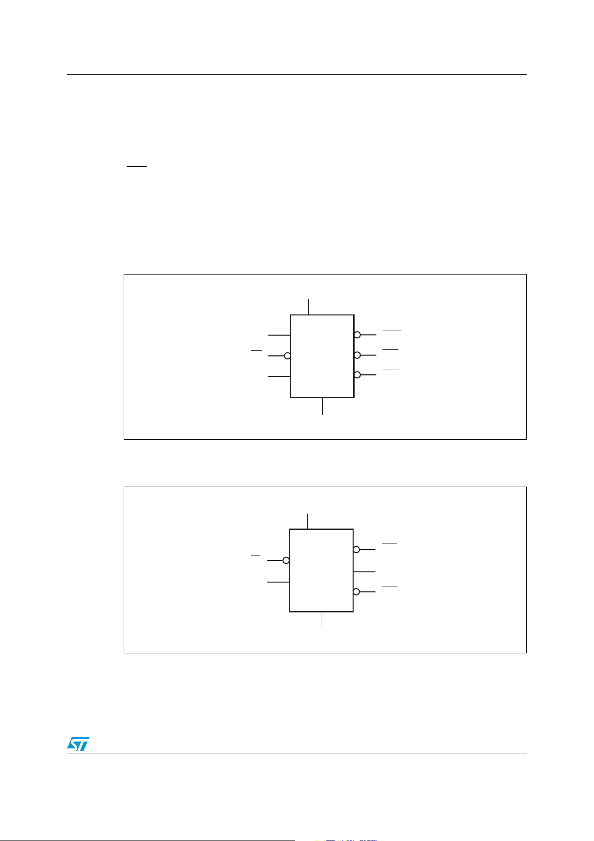
Figure 1. Logic diagram (STM706T/S/R and STM706P)
V
CC
CC
input
WDI
STM706T/S/R,
MR
PFI
1. For STM706P only.
STM706P
Figure 2. Logic diagram (STM708T/S/R)
V
CC
MR
PFI
STM708T/S/R
WDO
RST (RST)
PFO
V
SS
RST
RST
PFO
(1)
AI08841
V
SS
AI08842
Doc ID 10518 Rev 11 5/32
Description STM706T/S/R, STM706P, STM708T/S/R
Table 2. Signal names
Symbol Name
MR
Push-button reset input
WDI Watchdog input
WDO
RST
RST
V
CC
(1)
Watchdog output
Active-low reset output
Active-high reset output
Supply voltage
PFI Power-fail input
PFO
Power-fail output
V
Ground
SS
NC No connect
1. For STM706P and STM708T/S/R only.
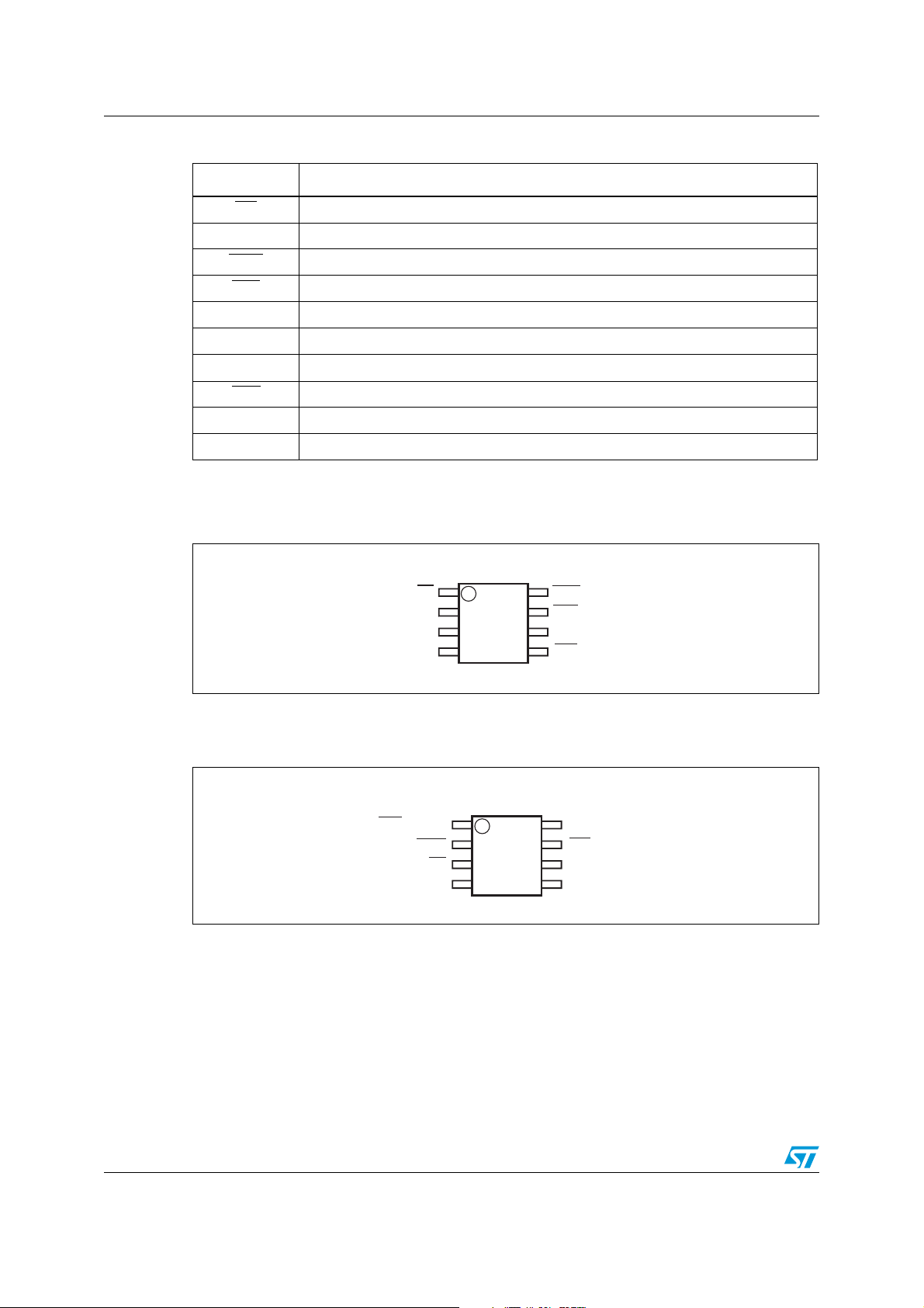
Figure 3. STM706T/S/R and STM706P SO8 connections
SO8
8
7
6
5
WDO
RST(RST)
WDI
PFO
SS
1
2
3
4
MR
V
CC
V
PFI
(1)
AI08837
1. For STM706P reset output is active-high.
Figure 4. STM706T/S/R and STM706P TSSOP8 connections
TSSOP8
1
2
3
4
8
WDI
7
PFO
PFI
6
V
5
SS
RST(RST)
WDO
V
1. For STM706P reset output is active-high.
(1)
MR
CC
AI08838
6/32 Doc ID 10518 Rev 11
STM706T/S/R, STM706P, STM708T/S/R Description
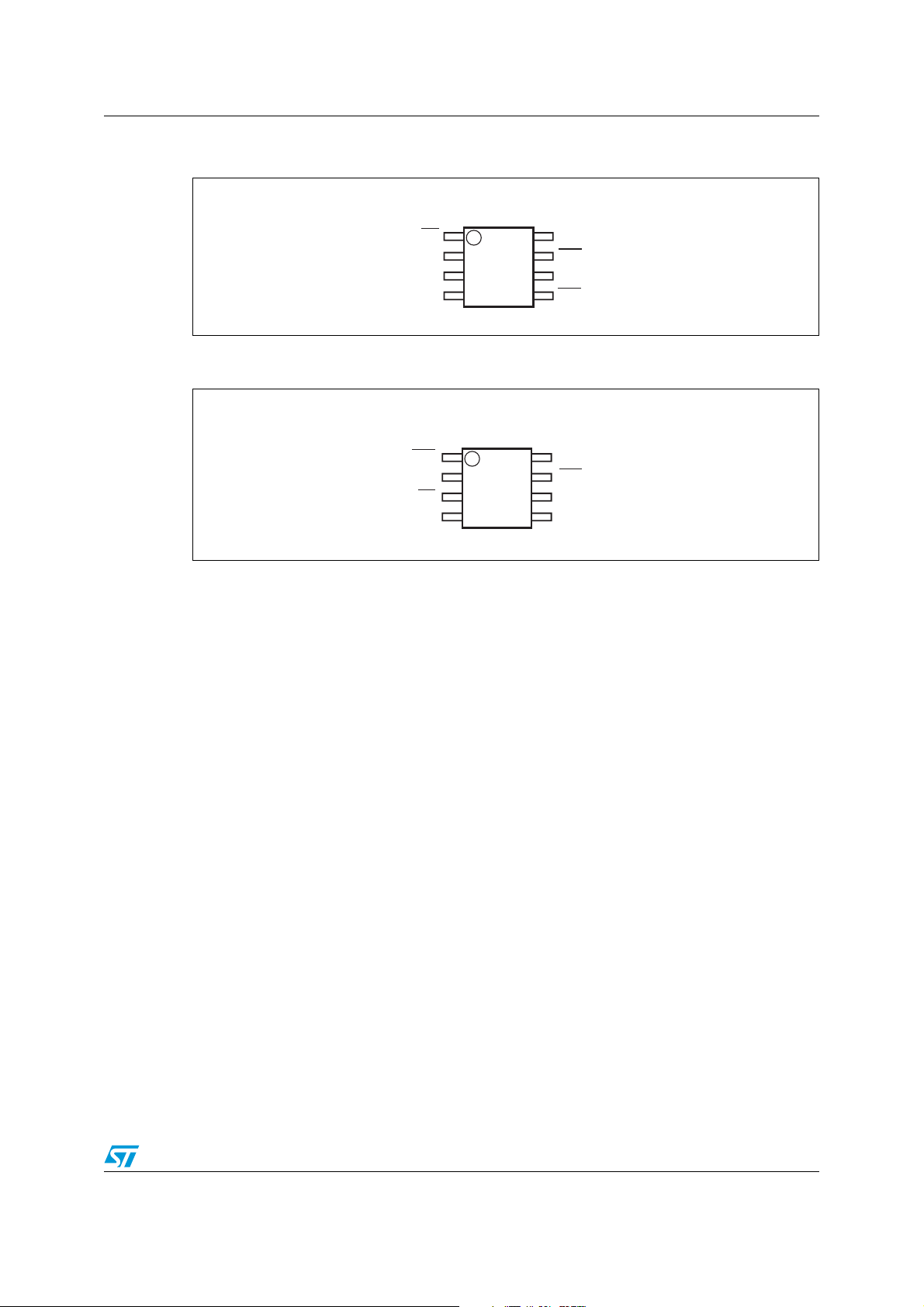
Figure 5. STM708T/S/R SO8 connections
SO8
RST
MR
V
CC
V
SS
PFI
1
2
3
4
8
7
RST
NC
6
5
PFO
AI08839
Figure 6. STM708T/S/R TSSOP8 connections
TSSOP8
RST
RST
MR
V
CC
1
2
3
4
8
NC
7
PFO
6
PFI
V
5
SS
AI08840
Doc ID 10518 Rev 11 7/32

Pin descriptions STM706T/S/R, STM706P, STM708T/S/R
2 Pin descriptions
2.1 MR
A logic low on MR asserts the reset output. Reset remains asserted as long as MR is low
and for t
driven from a TTL or CMOS logic line, or shorted to ground with a switch. Leave open if
unused.
2.2 WDI
If WDI remains high or low for 1.6 s, the internal watchdog timer runs out and reset (or
WDO
sees a rising or falling edge.
The watchdog function cannot be disabled by allowing the WDI pin to float.
2.3 WDO
after MR returns high. This active-low input has an internal pull-up. It can be
rec
) is triggered. The internal watchdog timer clears while reset is asserted or when WDI
WDO goes low when a transition does not occur on WDI within 1.6 s, and remains low until
a transition occurs on WDI (indicating the watchdog interrupt has been serviced). WDO
goes low when V
goes high as soon as V
Note: For those devices with a WDO
is connected to MR
falls below the reset threshold; however, unlike the reset output, WDO
CC
exceeds the reset threshold. Output type is push-pull.
CC
.
2.4 RST
Pulses low for t
threshold or when MR
reset threshold, the watchdog triggers a reset, or MR
when triggered, and stays low whenever VCC is below the reset
rec
is a logic low. It remains low for t
2.5 RST
Pulses high for t
threshold or when MR
reset threshold, the watchdog triggers a reset, or MR
when triggered, and stays high whenever VCC is above the reset
rec
is a logic high. It remains high for t
2.6 PFI
also
output, a watchdog timeout will not trigger reset unless WDO
after either VCC rises above the
rec
goes from low to high.
after either VCC falls below the
rec
goes from high to low.
When PFI is less than V
ground if unused.
8/32 Doc ID 10518 Rev 11
, PFO goes low; otherwise, PFO remains high. Connect to
PFI

STM706T/S/R, STM706P, STM708T/S/R Pin descriptions
2.7 PFO
When PFI is less than V
push-pull. PFO
during the period PFO
Table 3. Pin description
pin is not supposed to be forced low by a processor. MR input is gated off
, PFO goes low; otherwise, PFO remains high. Output type is
PFI
is forced low. Leave open if unused.
Pin
STM706P STM706T/S/R STM708T/S/R
Name Function
SO8 TSSOP8 SO8 TSSOP8 SO8 TSSOP8
1 3 1 3 1 3 MR
Push-button reset input
6 8 6 8 — — WDI Watchdog input
8 2 8 2 — — WDO
— — 7 1 7 1 RST
Watchdog output (push-pull)
Active-low reset output
7 1 — — 8 2 RST Active-high reset output
2 4 2 4 2 4 V
Supply voltage
CC
4 6 4 6 4 6 PFI Power-fail input
5 7 5 7 5 7 PFO
3 5 3 5 3 5 V
Power-fail output (push-pull)
Ground
SS
— — — — 6 8 NC No connect
Figure 7. Block diagram (STM706T/S/R and STM706P)
WDI
V
CC
MR
PFI
1. For STM706P only.
V
CC
WDI
transitional
detector
V
RST
V
PFI
WATCHDOG
TIMER
COMPARE
COMPARE
t
rec
generator
WDO
RST (RST)
PFO
(1)
AI08829
Doc ID 10518 Rev 11 9/32
Pin descriptions STM706T/S/R, STM706P, STM708T/S/R
Figure 8. Block diagram (STM708T/S/R)
V
CC
MR
V
RST
V
CC
COMPARE
t
rec
generator
RST
RST
PFI
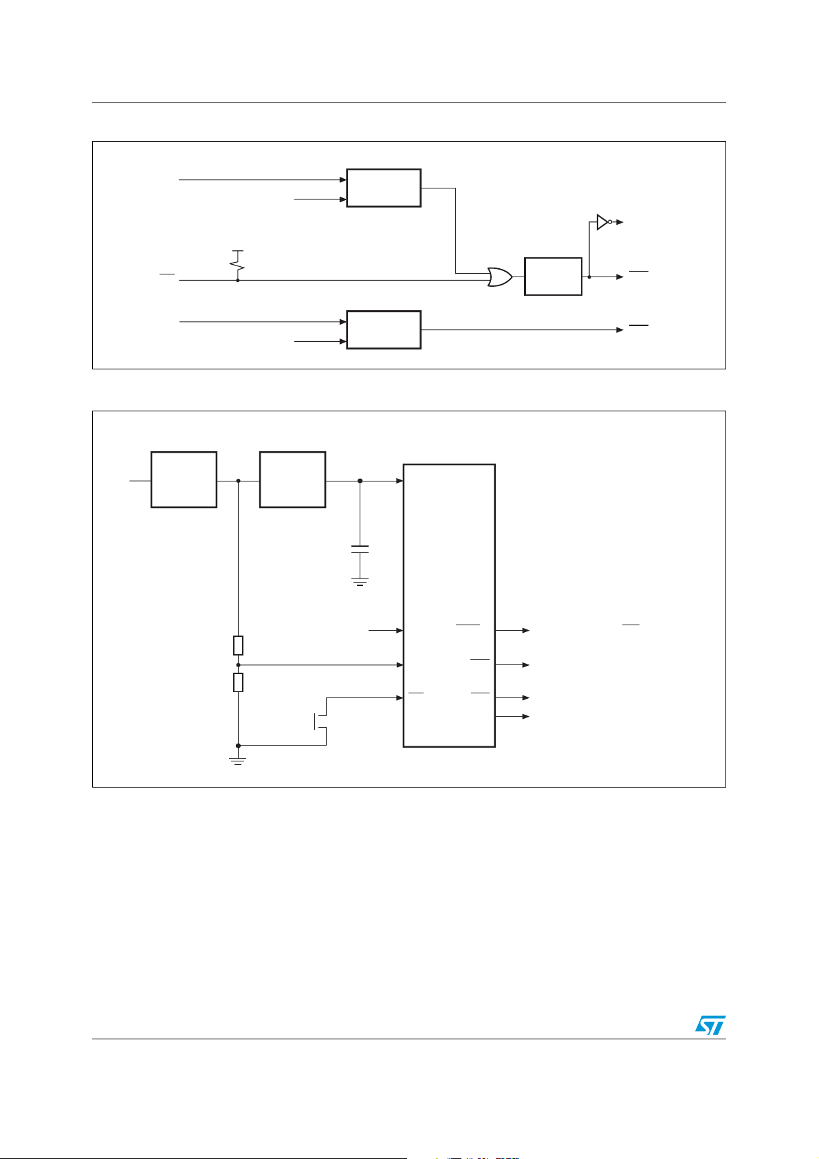
Figure 9. Hardware hookup
Unregulated
voltage
R1
R2
Regulator
V
IN
V
PFI
V
CC
0.1 μF
From microprocessor
Push-button
COMPARE
V
CC
STM706T/S/R;
STM706P;
STM708T/S/R
(1)
WDI
PFI
MR
WDO
PFO
RST
RST
(2)
(1)
PFO
AI08830
To microprocessor IRQ
To microprocessor NMI
To microprocessor reset
1. For STM706T/S/R and STM706P.
2. For STM706P and STM708T/S/R.
10/32 Doc ID 10518 Rev 11
AI08843
 Loading...