

Page 1
Features
■ Three 5 V power supply options:
–power jack
– USB connector
– daughterboard
■ Boot from user Flash, system memory or
SRAM
■ I2S audio DAC, stereo audio jack
■ 2 GByte microSD Card™ or bigger
■ Both A and B type smartcard support
■ I2C compatible serial interface 64 Kbit
EEPROM, MEMS and I/O expander
■ RS-232 channel
■ IrDA transceiver
■ USB OTG full speed, USB microAB connection
■ IEEE-802.3-2002 compliant ethernet
connector
■ Two channels of CAN 2.0A/B compliant
connection
■ Inductor motor control connector
■ JTAG and trace debug support
■ 3.2” 240x320 TFT color LCD with touch screen
■ Joystick with 4-direction control and selector
■ Reset, wakeup, tamper and user buttons
■ 4 color LEDs
■ RTC with backup battery
■ MCU consumption measurement circuit
■ Extension connector for daughterboard or
wrapping board
Table 1. Device summary
Order code Reference
STM3210C-EVAL
STM3210C-EVAL evaluation board
Data brief
Description
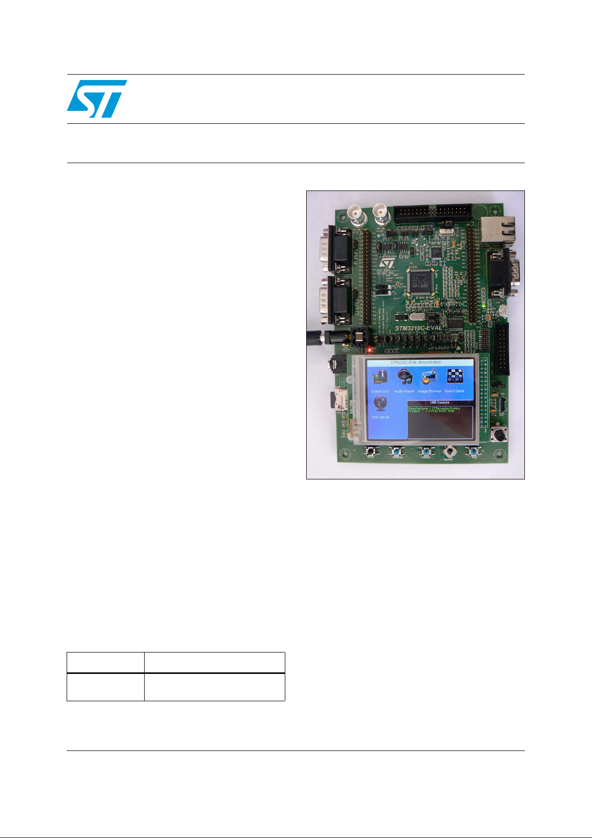
The STM3210C-EVAL evaluation board is a
complete development platform for
STMicroelectronic's ARM Cortex-M3 core-based
STM32F107VCT microcontroller. The range of
hardware features on the board help you to
evaluate all peripherals (USB-OTG FS, ethernet,
motor control, CAN, microSD Card
USART, audio DAC, MEMS, EEPROM and more)
and dev elop your own applications.
Extension headers make it easy to connect a
daughterboard or wrapping boar d for y our specific
application.
TM
, smartcard,
STM3210C-EVAL
August 2010 Doc ID 17799 Rev 1 1/3
For further information contact your local STMicroelectronics sales office .
STM32F107VCT evaluation
board
www.st.com
3
Page 2
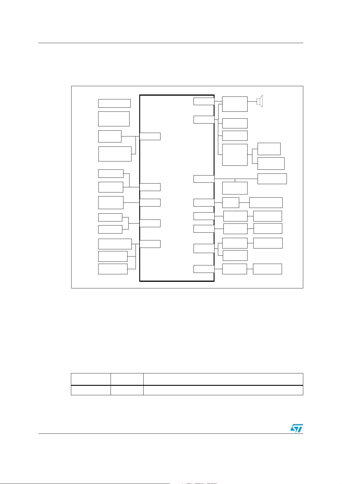
STM3210C-EVAL hardware block diagram
Figure 1 is a block diagram of the STM3210C-EVAL hardware.
Figure 1. Hardware block diagram
STM3210C-EVAL
3.3V regulator
MCU
consumption
measurement
LEDs,Key
Extension
connector for
GPIOs
TFT LCD
MicroSD
Card
MC control
connector
JTAG
Trace
2 BNC connector
Potentiometer
Battery voltage
measurement
GPIO
SPI3
MC
Debug
ADC
STM32F107VCT
I2S2
I2C1
OTG
MII/RMII
CAN1
CAN2
USART2
USART3
Audio DAC
MEMS
EEPROM
I/O expander
USB power
switch
PHY
CAN
transceiver
CAN
transceiver
RS-232
transceiver
IrDA
transceiver
Smartcard
interface
Joystick
Touchscreen
USB microAB
connector
Integrated RJ45
connector
CAN
DB9 connector
CAN
DB9 connector
USART 2
DB9 connector
Smartcard
connector
Demonstration software
Demonstration software is pre loaded in the board’s Flash memory for easy demonstration of
the device peripherals in stand-alo ne mode. For more information and to download the
latest version, refer to www.st.com.
Revision history
Table 2. Document revision history
Date Revision Changes
06-Aug-2010 1 Initial release.
2/3 Doc ID 17799 Rev 1
Page 3

STM3210C-EVAL
I
e
r
y
t
A
P
o
l
N
is
d
ts
o
h
t
U
D
W
D
W
S
O
U
T
R
G
A
Y,
D
E
G
R
id
a
y
l
Please Read Carefully:
nformation in this document is provided solely in connection with ST products. STMicroelectronics NV and its subsidiaries (“ST”) reserve th
ight to make changes, corrections, modifications or improvements, to this document, and the products and services described herein at an
ime, without notice.
ll ST products are sold pursuant to ST’s terms and conditions of sale.
urchasers are solely respon sibl e fo r the c hoic e, sele cti on an d use o f the S T prod ucts and s ervi ces d escrib ed he rein , and ST as sumes n
iability whatsoever relati ng to the choice, selection or use o f the ST products and services described herein.
o license, express or implied, by estoppel or otherwise, to any intellectual property rights is granted under this document. If any part of th
ocument refers to any third pa rty p ro duc ts or se rv ices it sh all n ot be deem ed a lice ns e gr ant by ST fo r t he use of su ch thi r d p arty produc
r services, or any intellectua l property c ontained the rein or consi dered as a warr anty coverin g the use in any manner whats oever of suc
hird party products or servi ces or any intellectual propert y contained therein.
NLESS OTHERWISE SET FORTH IN ST’S TERMS AND CONDITIONS OF SALE ST DISCLAIMS ANY EXPRESS OR IMPLIE
ARRANTY WITH RESPECT TO THE USE AND/OR SALE OF ST PRODUCTS INCLUDING WITHOUT LIMITATION IMPLIE
ARRANTIES OF MERCHANTABILITY, FITNESS FOR A PARTICUL AR PURPOSE (AND T HEIR EQUIVALE NTS UNDER THE LAW
F ANY JURISDICTION), OR INFRINGEMENT OF ANY PATENT, COPYRIGHT OR OTHER INTELLECTUAL PROPERTY RIGHT.
NLESS EXPRESSLY APPROVED IN WRITING BY AN AUTHORIZED ST REPRESENTATIVE, ST PRODUCTS ARE NO
ECOMMENDED, AUTHORIZED OR WARRANTED FOR USE IN MILITARY, AIR CRAFT, SPACE, LIFE SAVING, OR LIFE SUSTAININ
PPLICATIONS, NOR IN PRODUCTS OR SYSTEMS WHERE FAILURE OR MALFUNCTION MAY RESULT IN PERSONAL INJ UR
EATH, OR SEVERE PROPERTY OR ENVIRONMENTAL DAMAGE. ST PRODUCTS WHICH ARE NOT SPECIFIED AS "AUTOMOTIV
RADE" MAY ONLY BE USED IN AUTOMOTIVE APPLICATIONS AT USER’S OWN RISK.
esale of ST products with provisions different from the statements and/or technical features set forth in this document shall immediately vo
ny warranty granted by ST for the ST product or service described herein and shall not create or extend in any manner whatsoever, an
iability of ST.
ST and the ST logo are trademarks or registered trademarks of ST in vari ous countries.
Information in this document su persedes and replaces all information previously supplied.
The ST logo is a registered trademark of STMicroelectronics. All other names are the property of their respective owners.
© 2010 STMicroelectronics - All rights reserved
STMicroelectronics group of compan ie s
Australia - Belgium - Brazil - Canada - China - Czech Republic - Finland - Fran ce - Germany - Hong Kong - India - Israel - I taly - Japan -
Malaysia - Malta - Morocco - Philip pines - Singapore - Spain - Sweden - Switzerland - United Kingdom - United States of America
www.st.com
Doc ID 17799 Rev 1 3/3
 Loading...