

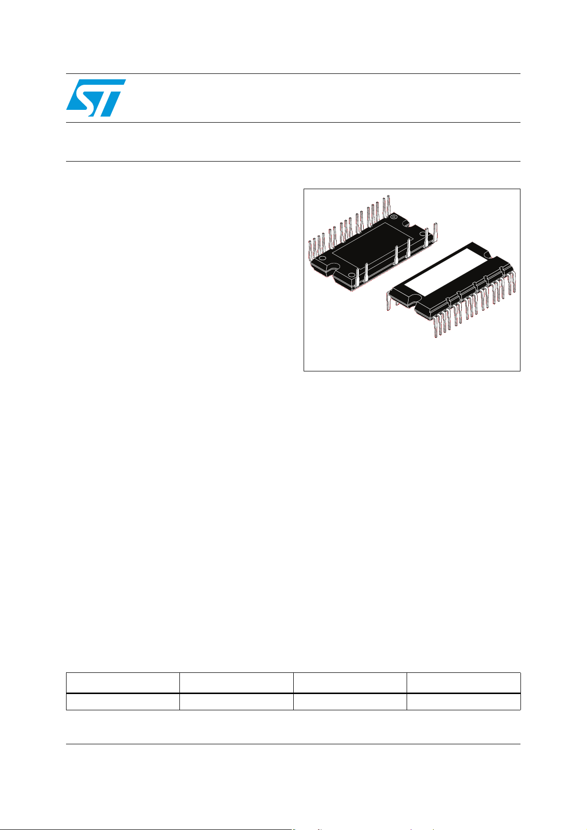
SLLIMM™ (small low-loss intelligent molded module)
IPM, single phase - 40 A, 600 V ultra fast IGBT
Features
■ IPM 40 A, 600 V single phase IGBT including
control ICs for gate driving and free-wheeling
diodes
■ IGBTs with excellent trade-off between low
conduction losses and fast switching
performance
■ V
■ 3.3 V, 5 V, 15 V CMOS/TTL inputs
comparators with hysteresis and pull down /
pull up resistors
■ Undervoltage lockout
■ Internal bootstrap diode
■ Dead time and interlocking function
■ Smart shutdown function
■ Comparator for fault protection against over
temperature and overcurrent
■ DBC substrate leading to low thermal
resistance
■ Isolation rating of 2500 V
■ 4.7 kΩ NTC UL recognized for temperature
control
■ UL recognition pending (in agreement to
QQQX2.E81734 - Electrically-isolated
semiconductor devices - component)
negative temperature coefficient
CE(sat)
rms
/min
STGIPS40W60L1
Preliminary data
SDIP-22L
Description
This intelligent power module provides a compact,
high performance AC motor drive for a simple and
rugged design. It targets high frequency
converters. It combines ST proprietary control ICs
with the most advanced IGBT and diode
technologies tailored to high switching frequency
operation. SLLIMM™ is a trademark of
STMicroelectronics.
Applications
■ Power factor correction for compressors
Table 1. Device summary
Order code Marking Package Packaging
STGIPS40W60L1 GIPS40W60L1 SDIP-22L Tube
January 2012 Doc ID 018866 Rev 2 1/21
This is preliminar y information on a new product now in development or undergoing evaluation. Details are subject to
change without notice.
www.st.com
21

Contents STGIPS40W60L1
Contents
1 Internal schematic diagram and pin configuration . . . . . . . . . . . . . . . . 3
2 Electrical ratings . . . . . . . . . . . . . . . . . . . . . . . . . . . . . . . . . . . . . . . . . . . . 5
2.1 Absolute maximum ratings . . . . . . . . . . . . . . . . . . . . . . . . . . . . . . . . . . . . . 5
2.2 Thermal data . . . . . . . . . . . . . . . . . . . . . . . . . . . . . . . . . . . . . . . . . . . . . . . 6
3 Electrical characteristics . . . . . . . . . . . . . . . . . . . . . . . . . . . . . . . . . . . . . 7
3.1 Control part . . . . . . . . . . . . . . . . . . . . . . . . . . . . . . . . . . . . . . . . . . . . . . . . 9
3.1.1 NTC thermistor . . . . . . . . . . . . . . . . . . . . . . . . . . . . . . . . . . . . . . . . . . . 12
3.1.2 Dead time . . . . . . . . . . . . . . . . . . . . . . . . . . . . . . . . . . . . . . . . . . . . . . . 13
3.2 Recommendations . . . . . . . . . . . . . . . . . . . . . . . . . . . . . . . . . . . . . . . . . . 14
4 Smart shutdown function . . . . . . . . . . . . . . . . . . . . . . . . . . . . . . . . . . . . 15
5 Package mechanical data . . . . . . . . . . . . . . . . . . . . . . . . . . . . . . . . . . . . 16
6 Revision history . . . . . . . . . . . . . . . . . . . . . . . . . . . . . . . . . . . . . . . . . . . 20
2/21 Doc ID 018866 Rev 2
STGIPS40W60L1 Internal schematic diagram and pin configuration
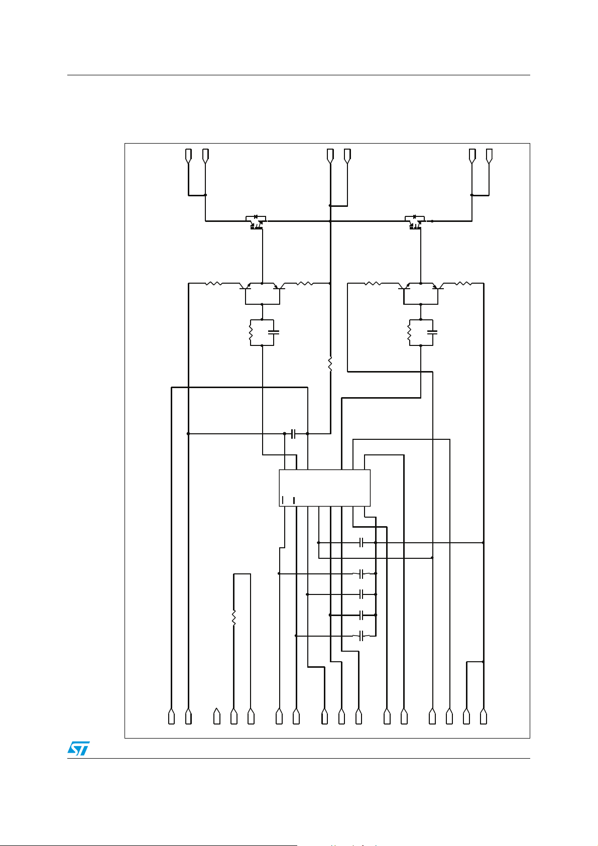
1 Internal schematic diagram and pin configuration
Figure 1. Internal schematic diagram
Pin22: P
Pin21: P
Pin19: PHASE
Pin20: PHASE
Pin18 : N
Pin17: N
LVG
CP+
OUT
HVG
Vboot
LIN
SD/OD
VCC
DT
HIN
Pin3: N C
Pin4: T1
Pin2: VBOOT
Pin 1: OUT
Pin5: T2
Pin7: /SD
Pin 6: /LIN
Pin8: H IN
OP+
GND
OPOUT
OP-
Pin10: OP-
Pin9: DT
Pin11: OPOUT
Pin13 : VCC
Pin12: OP+
Pin14: CIN
Pin15: GND
AM09386v2
Pin16: GND
Doc ID 018866 Rev 2 3/21
Internal schematic diagram and pin configuration STGIPS40W60L1
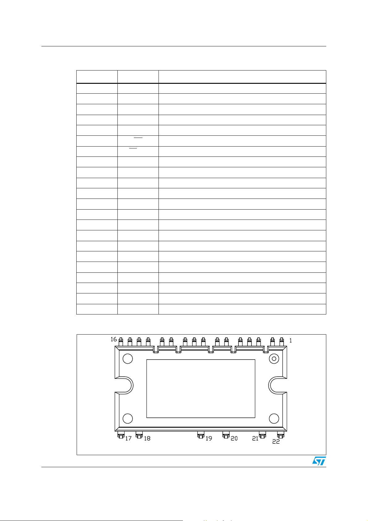
Table 2. Pin description
Pin Symbol Description
1OUT
2V
PHASE
boot
PHASE reference output
Bootstrap voltage
3 NC Not connected
4T
5T
1
2
6LIN
NTC thermistor terminal 1
NTC thermistor terminal 2
Low side logic input
7SD/OD Shutdown logic input (active low) / open drain (comparator output)
8 HIN High side logic input
9 DT Dead time setting
10 OP- Op amp inverting input
11 OP
OUT
Op amp output
12 OP+ Op amp non inverting input
13 V
CC
Low voltage power supply
14 CIN Comparator input
15 GND Ground
16 GND Ground
17 N Negative DC input
18 N Negative DC input
19 PHASE Phase output
20 PHASE Phase output
21 P Positive DC input
22 P Positive DC input
Figure 2. Pin layout (bottom view)
Marking area
4/21 Doc ID 018866 Rev 2
AM06017v1
STGIPS40W60L1 Electrical ratings
2 Electrical ratings
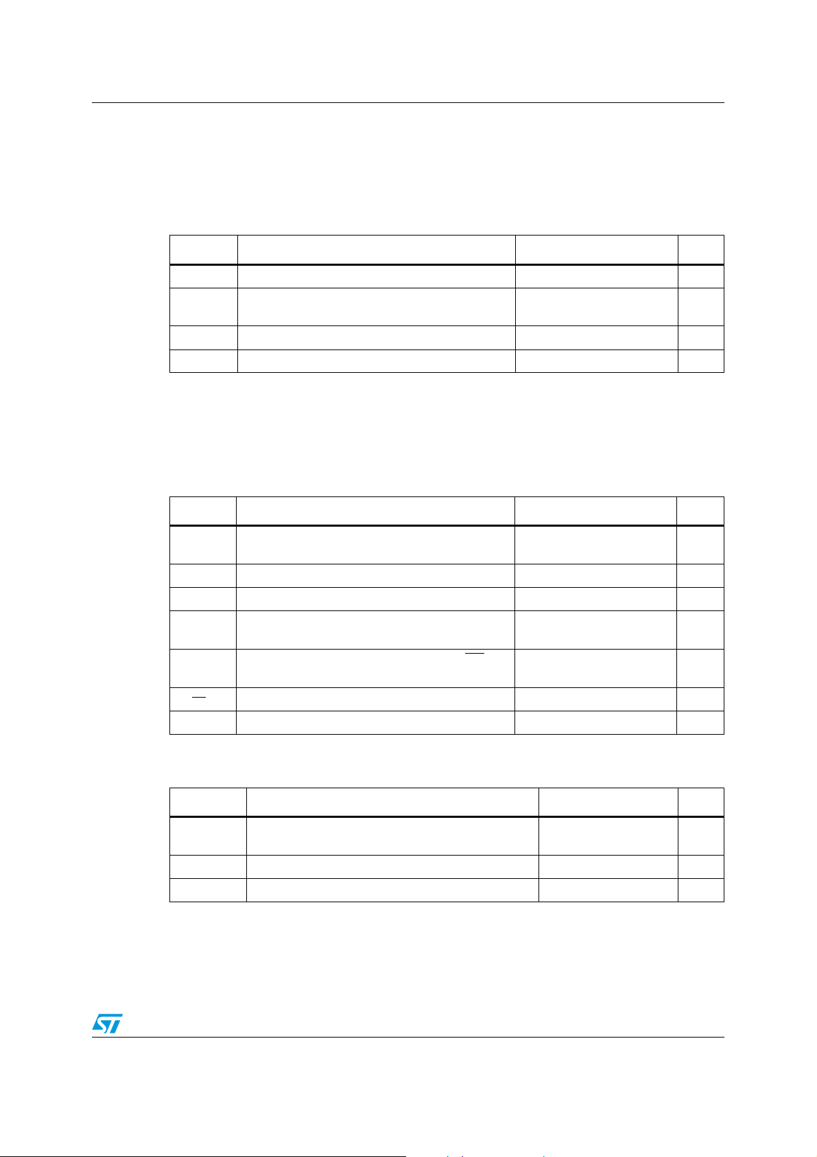
2.1 Absolute maximum ratings
Table 3. Inverter part
Symbol Parameter Value Unit
± I
V
± I
P
CES
CP
TOT
Each IGBT collector emitter voltage (V
Each IGBT continuous collector current
(1)
C
(2)
= 25°C
at T
C
Each IGBT pulsed collector current 80 A
= 0) 600 V
IN
40 A
Each IGBT total dissipation at TC = 25°C 100 W
1. Calculated according to the iterative formula:
ICTC()
------------ ----------------- --------------- ----------------- ----------------- ----------------- --------=
R
thj c–
T
V
CE sat()max()Tjmax()ICTC
–
jmax()TC
(),()×
2. Pulse width limited by max junction temperature
Table 4. Control part
Symbol Parameter Value Unit
V
V
V
V
OUT
CIN
boot
V
Output voltage applied between
- GND
OUT
Low voltage power supply -0.3 to +21 V
CC
V
boot
- 21 to V
boot
Comparator input voltage -0.3 to VCC +0.3 V
Bootstrap voltage applied between
- OUT
V
boot
Logic input voltage applied between HIN, LIN and
IN
GND
-0.3 to 620 V
-0.3 to 15 V
+ 0.3 V
V
dV
SD/OD
OUT
Open-drain voltage -0.3 to 15 V
/dt Allowed output slew rate 50 V/ns
Table 5. Total system
Symbol Parameter Value Unit
V
ISO
(1)
T
J
T
C
1. The maximum junction temperature rating of the power chips integrated within the SDIP module is 150°C
(@T
limited to T
Isolation withstand voltage applied between each
pin and heatsink plate (AC voltage, t = 60 sec.)
2500 V
Operating junction temperature for IGBT and diode -40 to 150 °C
Module case operation temperature -40 to 125 °C
≤ 100°C). To ensure safe operation of the SDIP module, the average junction temperature should be
C
(avg) ≤ 125°C (@TC ≤ 100°C).
j
Doc ID 018866 Rev 2 5/21
Electrical ratings STGIPS40W60L1
2.2 Thermal data
Table 6. Thermal data
Symbol Parameter Value Unit
R
thJC
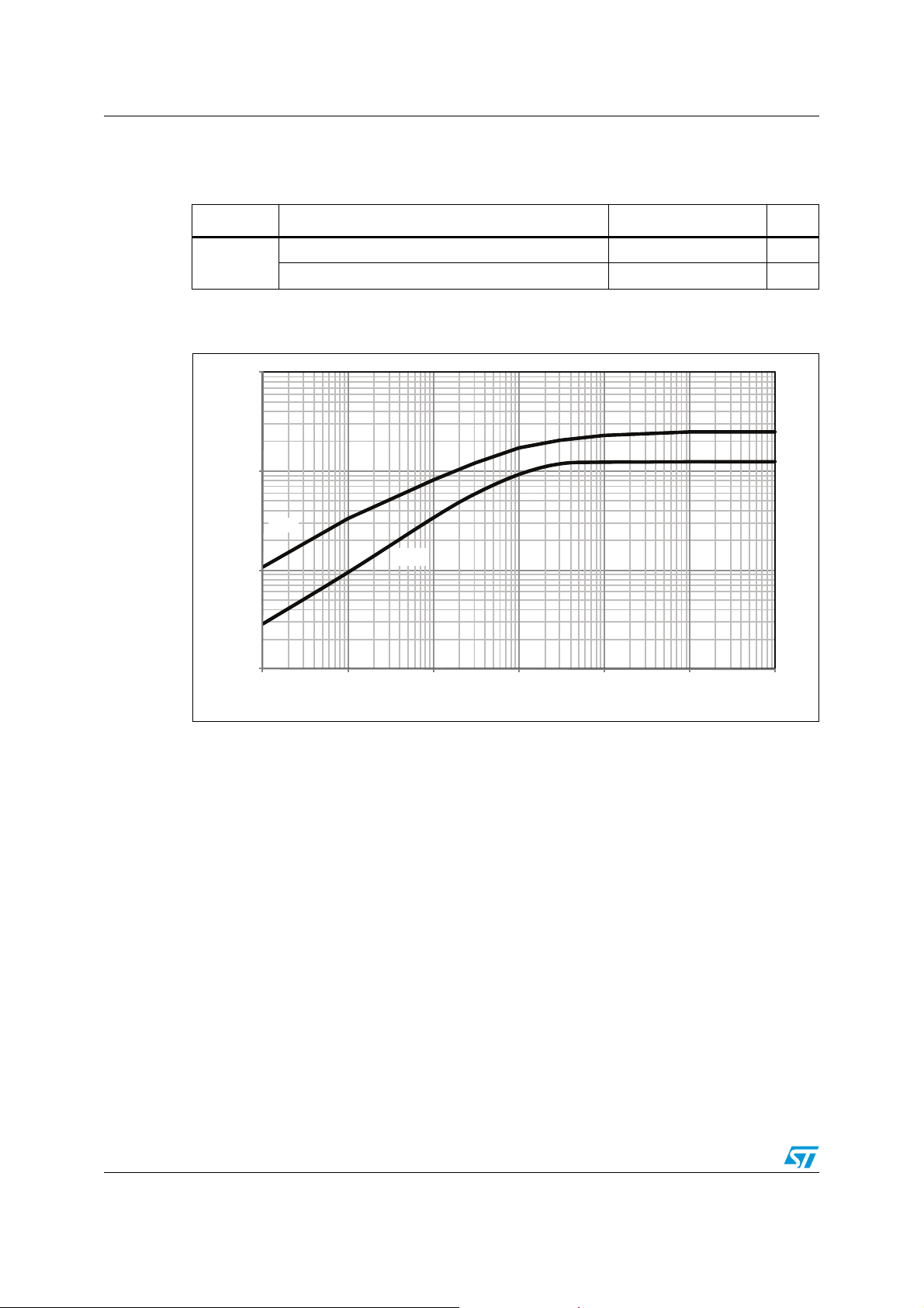
Figure 3. Transient thermal impedance IGBT/diode - inverter
Thermal resistance junction-case single diode 2.5 °C/W
10
1
[K/W]
Diode
thj-c
Z
IGBT
0.1
0.01
1.E-04 1.E-03 1.E-02 1.E-01 1.E+00 1.E+01 1.E+02
time [s]
Thermal resistance junction-case single IGBT 1.25 °C/W
AM09385v1
6/21 Doc ID 018866 Rev 2
STGIPS40W60L1 Electrical characteristics
3 Electrical characteristics
TJ = 25 °C unless otherwise specified.
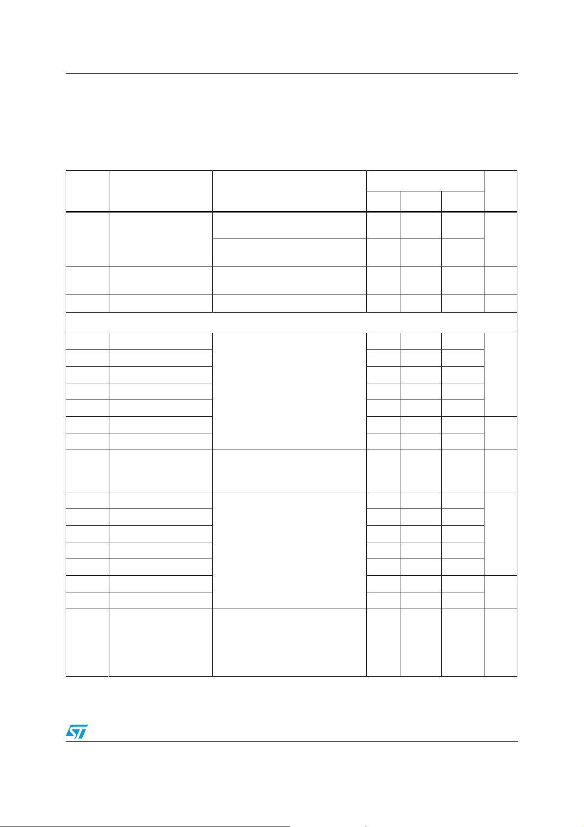
Table 7. Inverter part
Value
Symbol Parameter Test conditions
Min. Typ. Max.
Unit
V
CE(sat)
I
CES
V
Collector-emitter
saturation voltage
Collector-cut off current
= 0 "logic state")
(V
IN
Diode forward voltage VIN = 0 "logic state", IF = 30A - 2.5 V
F
Switching on/off (inductive load)
t
t
c(on)
t
t
c(off)
E
E
di/dt
t
t
c(on)
t
t
c(off)
E
E
di/dt
Tur n - on t i m e
on
Crossover time (on) - 80 -
Turn-off time - 320 -
off
Crossover time (off) - 125 -
t
Reverse recovery time - 115 -
rr
Turn-on switching losses - 585 -
on
Turn-off switching losses - 600 -
off
Rate of rise of on-state
(on)
current
Tur n - on t i m e
on
Crossover time (on) - 110 -
Turn-off time - 420 -
off
Crossover time (off) - 140 -
t
Reverse recovery time - 150 -
rr
Turn-on switching losses - 930 -
on
Turn-off switching losses - 780 -
off
Rate of rise of on-state
(on)
current
VCC = V
state", I
V
CC
state", I
V
CE
(1)
V
DD
V
CC
= V
= 410 V,
= V
= 15 V, VIN = 1 "logic
boot
= 30 A
C
= 15 V, VIN = 1 "logic
boot
= 30 A, TJ = 125 °C
C
= 600 V, V
boot
CC
= 15 V,
= V
VIN = 1 "logic state" (see
IC = 30 A (see
Figure 4
VDD = 410 V, VCC = V
V
= 1 "logic state" (see
IN
IC = 80 A (see
V
= 410 V,
DD
VCC = V
V
= 1 "logic state" (see
IN
boot
Figure 4
= 15 V,
IC = 30 A, TJ = 125 °C
(see
Figure 4
= 410 V,
V
DD
VCC = V
boot
and 5)
= 15 V,
VIN = 1 "logic state" (see
I
= 80 A, TJ = 125 °C
C
(see
Figure 4
and 5)
-2.02.5
-1.7
= 15 V, - 500 µA
Boot
- 410 -
Ta bl e 1 3
)
and 5)
= 15 V,
boot
Ta bl e 1 3
),
- 2500 - A/µs
and 5)
- 550 -
Ta bl e 1 3
Ta bl e 1 3
)
)
- 2100 - A/µs
V
ns
µJ
ns
µJ
1. tON and t
under the internally given gate driving condition. Parameter values take into account a 20 nH stray inductance.
include the propagation delay time of the internal drive. t
OFF
C(ON)
and t
are the switching time of IGBT itself
C(OFF)
Doc ID 018866 Rev 2 7/21
 Loading...