

ST STGB6NC60HD, STGB6NC60HD-1, STGF6NC60HD, STGP6NC60HD User Manual

3
查询STGB6NC60HD-1供应商
N-channel 600V - 7A - I2PAK / D2PAK / TO-220 / TO-220FP
Features
V
Type V
STGB6NC60HD
STGB6NC60HD-1
STGP6NC60HD
STGF6NC60HD
CES
600V
600V
600V
600V
CE(sat)
STGB6NC60HD - STGB6NC60HD-1
STGF6NC60HD - STGP6NC60HD
Very fast PowerMESH™ IGBT
max
@25°C
<2.5V
<2.5V
<2.5V
<2.5V
I
C
@100°C
7A
7A
7A
3A
3
2
1
TO-220FPTO-220
2
1
■ Low on voltage drop (V
■ Low C
RES
/ C
ratio (no cross-conduction
IES
cesat
)
susceptibility)
■ Very soft ultra fast recovery antiparallel diode
■ High frequency operation
Description
Using the latest high voltage technology based on
a patented strip layout, STMicroelectronics has
designed an advaced family of IGBTs, the
PowerMESH™ IGBTs, with outstanding
performances. The suffix “H” identifies a family
optimized for high frequency application in order
to achieve very high switching performances
(reduced tfall) mantaining a low voltage drop.
Applications
■ High frequency inverters
■ SMPS and PFC in both hard switch and
resonant topologies
■ Motor drivers
3
1
D²PAK
I2PAK
Internal schematic diagram
3
2
1
Order codes
Part number Marking Package Packaging
STGB6NC60HDT4 GB6NC60HD D²PAK Tape & reel
STGB6NC60HD-1 GB6NC60HD I²PAK Tube
STGP6NC60HD GP6NC60HD TO-220 Tube
STGF6NC60HD GF6NC60HD TO-220FP Tube
April 2007 Rev 4 1/18
www.st.com
18

Contents STGB6NC60HD/-1 - STGP6NC60HD - STGF6NC60HD
Contents
1 Electrical ratings . . . . . . . . . . . . . . . . . . . . . . . . . . . . . . . . . . . . . . . . . . . . 3
2 Electrical characteristics . . . . . . . . . . . . . . . . . . . . . . . . . . . . . . . . . . . . . 4
2.1 Electrical characteristics (curves) . . . . . . . . . . . . . . . . . . . . . . . . . . . . . 7
3 Test circuit . . . . . . . . . . . . . . . . . . . . . . . . . . . . . . . . . . . . . . . . . . . . . . . 10
4 Package mechanical data . . . . . . . . . . . . . . . . . . . . . . . . . . . . . . . . . . . . 11
5 Packaging mechanical data . . . . . . . . . . . . . . . . . . . . . . . . . . . . . . . . . . 16
6 Revision history . . . . . . . . . . . . . . . . . . . . . . . . . . . . . . . . . . . . . . . . . . . 17
2/18

STGB6NC60HD/-1 - STGP6NC60HD - STGF6NC60HD Electrical ratings
1 Electrical ratings
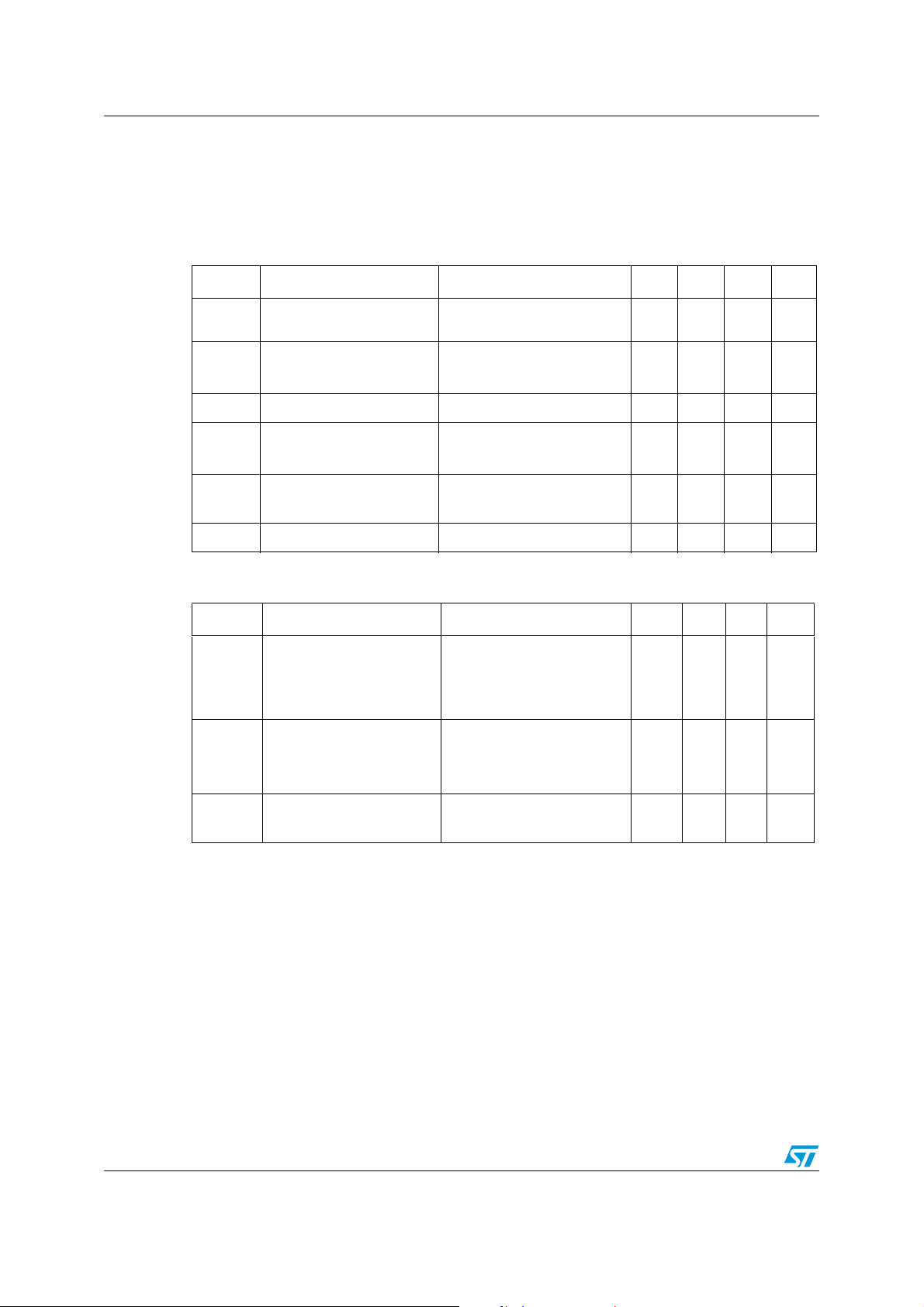
Table 1. Absolute maximum ratings
Value
Symbol Parameter
D²PAK/I²PAK/
TO-220
TO-220FP
Unit
V
CES
I
C
I
C
I
CM
V
I
P
TOT
V
ISO
T
T
T
1. Calculated according to the iterative formula::
2. Pulse width limited by max junction temperature
Collector-emitter voltage (VGS = 0)
(1)
Collector current (continuous) at TC = 25°C
(1)
Collector current (continuous) at TC = 100°C
(2)
Collector current (pulsed) 21 A
Gate-emitter voltage ±20 V
GE
Diode RMS forward current at Tc=25°C 10 A
F
Total dissipation at TC = 25°C
Insulation withstand voltage A.C.(t=1sec;Tc=25°C) -- 2500
Storage temperature
stg
Operating junction temperature
j
Maximum lead temperature for soldering purpose
l
(for 10sec. 1.6 mm from case)
ICTC()
---------------------------------- --------------------------------------------- -----------------------=
R
THJ C–VCESAT MAX()TCIC
T
JMAXTC
600 V
15 6 A
73A
56 20 W
– 55 to 150 °C
300 °C
–
,()×
Table 2. Thermal resistance
Symbol Parameter Value Unit
TO-220
Rthj-case Thermal resistance junction-case max
D²PAK
I²PAK
TO-220FP 5°C/W
Rthj-amb Thermal resistance junction-ambient max 62.5 °C/W
2°C/W
3/18
Electrical characteristics STGB6NC60HD/-1 - STGP6NC60HD - STGF6NC60HD
2 Electrical characteristics
(T
=25°C unless otherwise specified)
CASE
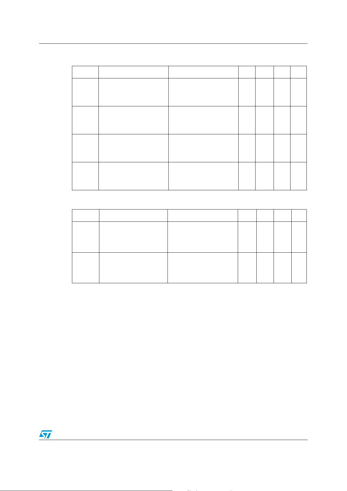
Table 3. Static
Symbol Parameter Test conditions Min. Typ. Max. Unit
V
BR(CES)
V
CE(sat)
V
GE(th)
I
CES
I
GES
g
Collector-emitter
breakdown voltage
Collector-emitter saturation
voltage
Gate threshold voltage
Collector cut-off current
= 0)
(V
GE
Gate-emitter leakage
current (V
Forward transconductance
fs
CE
= 0)
= 1mA, V
I
C
V
= 15V, IC= 3A
GE
V
= 15V, IC= 3A, Tc= 125°C
GE
= VGE, IC= 250 µA
V
CE
= Max rating,TC= 25°C
V
CE
= Max rating,TC= 125°C
V
CE
V
= ±20V , VCE= 0
GE
= 15V, IC= 3A
V
CE
GE
= 0
600 V
1.9
2.5 V
1.7
3.75 5.75 V
101µA
±100 nA
3S
Table 4. Dynamic
Symbol Parameter Test conditions Min. T yp. Max. Unit
C
C
C
Input capacitance
ies
Output capacitance
oes
Reverse transfer
res
capacitance
= 25V, f = 1MHz,
V
CE
= 0
V
GE
205
32
5.5
V
mA
pF
pF
pF
Q
g
Total gate charge
Q
Q
I
Gate-emitter charge
ge
Gate-collector charge
gc
Turn-off SOA minimum
CL
current
VCE = 390V, IC = 3A,
V
(see Figure 18)
V
R
4/18
= 15V,
GE
= 390V, Tj = 150°C,
clamp
= 10Ω, V
G
GE
= 15V
13.6
3.4
5.1
19 A
nC
nC
nC
STGB6NC60HD/-1 - STGP6NC60HD - STGF6NC60HD Electrical characteristics
Table 5. Switching on/off (inductive load)
Symbol Parameter Test conditions Min. Typ. Max. Unit
t
d(on)
t
(di/dt)
t
d(on)
t
(di/dt)
t
r(Voff
t
d(off
t
t
r(Voff
t
d(off
t
Turn-on delay time
Current rise time
r
Turn-on current slope
on
Turn-on delay time
Current rise time
r
Turn-on current slope
on
)
Off voltage rise time
)
Turn-off delay time
Current fall time
f
)
Off voltage rise time
)
Turn-off delay time
Current fall time
f
= 390V, IC = 3A
V
CC
= 10Ω, V
R
G
GE
= 15V,
Tj = 25°C (see Figure 19)
= 390V, IC = 3A
V
CC
= 10Ω, V
R
G
GE
= 15V,
Tj =125°C (see Figure 19)
VCC = 390V, IC = 3A,
R
= 10Ω , V
GE
= 25°C (see Figure 19)
T
J
= 390V, IC = 3A,
V
CC
R
= 10Ω , VGE =15V,
GE
GE
= 15V,
Tj = 125°C (see Figure 19)
12
5
612
13
4.3
560
40
76
100
60
98
124
A/µs
A/µs
Table 6. Switching energy (inductive load)
Symbol Parameter Test conditions Min. Typ. Max. Unit
(1)
E
on
E
off
E
E
on
E
off
E
1. Eon is the tun-on losses when a typical diode is used in the test circuit in figure 17. If the IGBT is offered in
a package with a co-pak diode, the co-pack diode is used as external diode. IGBTs & Diode are at the
same temperature (25°C and 125°C)
2. Turn-off losses include also the tail of the collector current
Turn-on switching losses
(2)
Turn-off switching losses
Total switching losses
ts
(1)
Turn-on switching losses
(2)
Turn-off switching losses
Total switching losses
ts
VCC = 390V, IC = 3A
=10Ω, VGE=15V,
R
G
Tj =25°C (see Figure 19)
= 390V, IC = 3A
V
CC
R
G
=10Ω, V
GE
= 15V,
Tj = 125°C (see Figure 19)
20
68
88
37
93
130
ns
ns
ns
ns
ns
ns
ns
ns
ns
ns
µJ
µJ
µJ
µJ
µJ
µJ
5/18
Electrical characteristics STGB6NC60HD/-1 - STGP6NC60HD - STGF6NC60HD
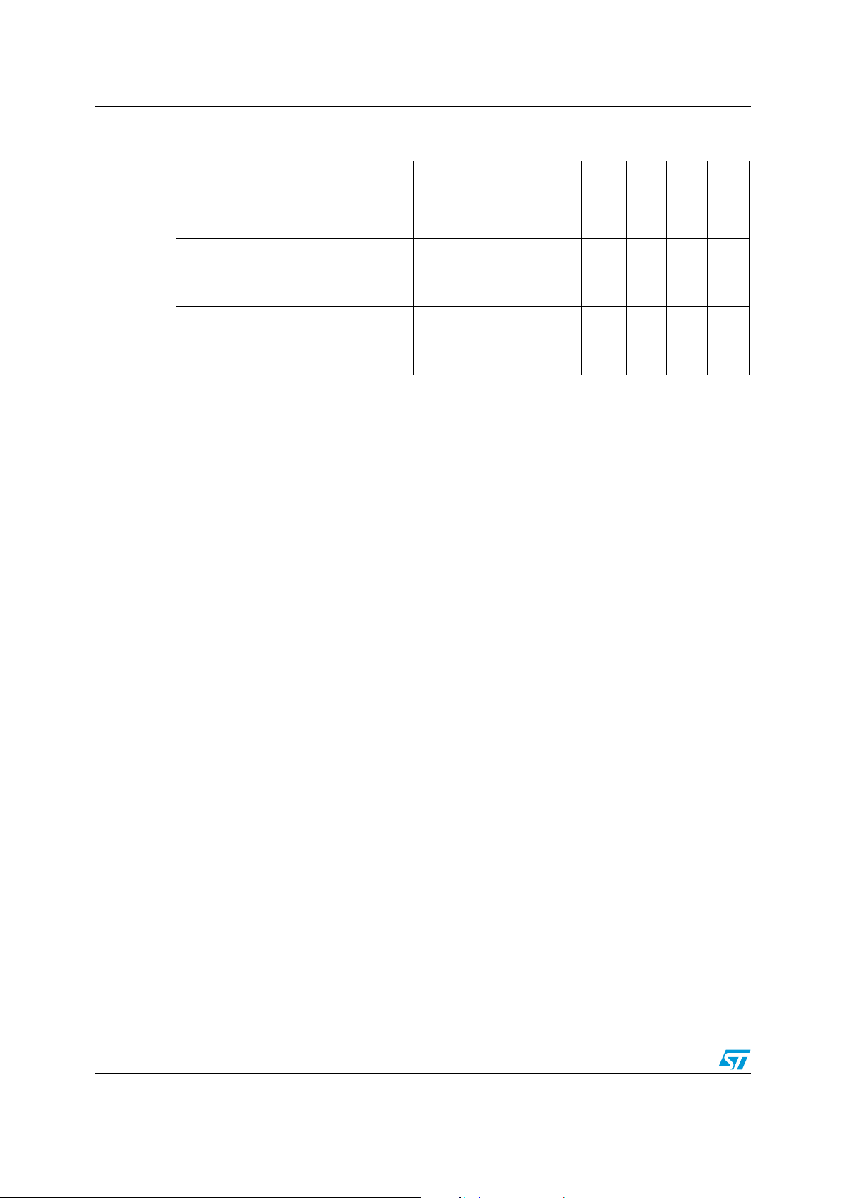
Table 7. Collector-emitter diode
Symbol Parameter Test conditions Min. Typ. Max. Unit
I
Q
I
Q
I
V
t
rr
rrm
t
rr
rrm
Forward on-voltage
f
Reverse recovery time
Reverse recovery charge
rr
Reverse recovery current
Reverse recovery time
Reverse recovery charge
rr
Reverse recovery current
= 1.5A
f
= 1.5A, Tj = 125°C
I
f
= 3A ,VR = 40V,
I
f
Tj = 25°C, di/dt = 100 A/µs
(see Figure 20)
= 3A ,VR = 40V,
I
f
Tj =125°C, di/dt = 100A/µs
(see Figure 20)
1.6
1.3
21
14
1.36
34
32
1.88
2.1 V
V
ns
nC
A
ns
nC
A
6/18
 Loading...