


Scalable digital microphone processor
Features
■ 8 digital processing channels each 24-bit
– 6 channels of PDM input
– 2 additional virtual channels
■ >100 dB SNR and dynamic range
■ Digital gain/attenuation +58 dB to -100 dB in
0.5 dB steps
■ Soft volume update
■ Individual channel and master level control
■ Up to 10 independent 32-bit user-
programmable biquads (EQ) per channel
■ Bass/treble tone control
■ Pre- and post-EQ full 8-channel input mix on all
8 channels
■ Dual independent limiters/compressors
■ Dynamic range compression or anti-clipping
modes
■ Individual channel and master soft/hard mute
2
■ 3 I
S data outputs
2
■ I
S data output channel mapping function
■ Independent channel volume and DSP bypass
■ Channel mapping of any input to any
processing channel
Applications
■ Tablets
■ Smartphones
■ Gaming
■ Audio conference sets
■ Legacy microphone-equipped devices
STA321MP
TQFP - 64
10 mm x 10 mm
Description
The STA321MP is a PDM high-performance
multichannel processor with ultra-low quiescent
current designed for general-purpose digital
microphone applications. The device is fully digital
and is comprised of three main sections. The first
section is the PDM input interface which can
accept up to six serial digital inputs. The second
section is a high-quality audio processor allowing
flexible channel mixing/muxing and provides up to
10 biquads for general sound equalization and
voice enhancement with independent volume
control. The last block is the I
which streams out the processed digital audio.
The output interface can also be programmed for
flexible channel mapping. The device offers some
of the most commonly required audio
enhancements such as programmable voice
tuning and equalization, limiter/compressor for
improved voice quality, multiband selection for
customizable microphone usage and configurable
wind-noise rejection. The embedded digital
processor allows offloading the microphone
processing from the main CPU or SoC, moving it
to the device.
Table 1. Device summary
VFQFPN - 56
8 mm x 8 mm
2
S output interface
Order code Package Packing
STA321MPL TQFP64 Tube
STA321MP VFQFPN56 Tube
February 2012 Doc ID 022647 Rev 1 1/50
www.st.com
1

Contents STA321MP
Contents
1 Block diagram . . . . . . . . . . . . . . . . . . . . . . . . . . . . . . . . . . . . . . . . . . . . . . 7
2 Pin connections . . . . . . . . . . . . . . . . . . . . . . . . . . . . . . . . . . . . . . . . . . . . . 8
3 Electrical specifications . . . . . . . . . . . . . . . . . . . . . . . . . . . . . . . . . . . . . 12
3.1 Absolute maximum ratings . . . . . . . . . . . . . . . . . . . . . . . . . . . . . . . . . . . . 12
3.2 Thermal data . . . . . . . . . . . . . . . . . . . . . . . . . . . . . . . . . . . . . . . . . . . . . . 12
3.3 Recommended operating conditions . . . . . . . . . . . . . . . . . . . . . . . . . . . . 12
3.4 Electrical specifications . . . . . . . . . . . . . . . . . . . . . . . . . . . . . . . . . . . . . . 13
4 Pin description . . . . . . . . . . . . . . . . . . . . . . . . . . . . . . . . . . . . . . . . . . . . 14
5I
2
C bus operation . . . . . . . . . . . . . . . . . . . . . . . . . . . . . . . . . . . . . . . . . . 15
5.1 Communication protocol . . . . . . . . . . . . . . . . . . . . . . . . . . . . . . . . . . . . . . 15
5.1.1 Data transition or change . . . . . . . . . . . . . . . . . . . . . . . . . . . . . . . . . . . . 15
5.1.2 Start condition . . . . . . . . . . . . . . . . . . . . . . . . . . . . . . . . . . . . . . . . . . . . 15
5.1.3 Stop condition . . . . . . . . . . . . . . . . . . . . . . . . . . . . . . . . . . . . . . . . . . . . 15
5.1.4 Data input . . . . . . . . . . . . . . . . . . . . . . . . . . . . . . . . . . . . . . . . . . . . . . . 15
5.2 Device addressing . . . . . . . . . . . . . . . . . . . . . . . . . . . . . . . . . . . . . . . . . . 15
5.3 Write operation . . . . . . . . . . . . . . . . . . . . . . . . . . . . . . . . . . . . . . . . . . . . . 16
5.3.1 Byte write . . . . . . . . . . . . . . . . . . . . . . . . . . . . . . . . . . . . . . . . . . . . . . . . 16
5.3.2 Multi-byte write . . . . . . . . . . . . . . . . . . . . . . . . . . . . . . . . . . . . . . . . . . . . 16
6 Application reference schematic . . . . . . . . . . . . . . . . . . . . . . . . . . . . . . 17
7 Registers . . . . . . . . . . . . . . . . . . . . . . . . . . . . . . . . . . . . . . . . . . . . . . . . . 18
7.1 Register summary . . . . . . . . . . . . . . . . . . . . . . . . . . . . . . . . . . . . . . . . . . 18
7.2 Register description . . . . . . . . . . . . . . . . . . . . . . . . . . . . . . . . . . . . . . . . . 21
7.2.1 Configuration register A (0x00) . . . . . . . . . . . . . . . . . . . . . . . . . . . . . . . 21
7.2.2 Configuration register C (0x02) - serial output formats . . . . . . . . . . . . . 23
7.2.3 Configuration register E (0x04) . . . . . . . . . . . . . . . . . . . . . . . . . . . . . . . 24
7.2.4 Configuration register F (0x05) . . . . . . . . . . . . . . . . . . . . . . . . . . . . . . . 24
7.2.5 Configuration register G (0x06) . . . . . . . . . . . . . . . . . . . . . . . . . . . . . . . 26
7.2.6 Configuration register H (0x07) . . . . . . . . . . . . . . . . . . . . . . . . . . . . . . . 27
2/50 Doc ID 022647 Rev 1

STA321MP Contents
7.2.7 Configuration register I (0x08) . . . . . . . . . . . . . . . . . . . . . . . . . . . . . . . . 28
7.2.8 Master mute register (0x09) . . . . . . . . . . . . . . . . . . . . . . . . . . . . . . . . . . 29
7.2.9 Master volume register (0x0A) . . . . . . . . . . . . . . . . . . . . . . . . . . . . . . . . 29
7.2.10 Channel 1 volume (0x0B) . . . . . . . . . . . . . . . . . . . . . . . . . . . . . . . . . . . 29
7.2.11 Channel 2 volume (0x0C) . . . . . . . . . . . . . . . . . . . . . . . . . . . . . . . . . . . 29
7.2.12 Channel 3 volume (0x0D) . . . . . . . . . . . . . . . . . . . . . . . . . . . . . . . . . . . 29
7.2.13 Channel 4 volume (0x0E) . . . . . . . . . . . . . . . . . . . . . . . . . . . . . . . . . . . 29
7.2.14 Channel 5 volume (0x0F) . . . . . . . . . . . . . . . . . . . . . . . . . . . . . . . . . . . . 30
7.2.15 Channel 6 volume (0x10) . . . . . . . . . . . . . . . . . . . . . . . . . . . . . . . . . . . . 30
7.2.16 Channel 7 volume (0x11) . . . . . . . . . . . . . . . . . . . . . . . . . . . . . . . . . . . . 30
7.2.17 Channel 8 volume (0x12) . . . . . . . . . . . . . . . . . . . . . . . . . . . . . . . . . . . . 30
7.2.18 Channel 1 volume trim, mute, bypass (0x13) . . . . . . . . . . . . . . . . . . . . 30
7.2.19 Channel 2 volume trim, mute, bypass (0x14) . . . . . . . . . . . . . . . . . . . . 30
7.2.20 Channel 3 volume trim, mute, bypass (0x15) . . . . . . . . . . . . . . . . . . . . 30
7.2.21 Channel 4 volume trim, mute, bypass (0x16) . . . . . . . . . . . . . . . . . . . . 31
7.2.22 Channel 5 volume trim, mute, bypass (0x17) . . . . . . . . . . . . . . . . . . . . 31
7.2.23 Channel 6 volume trim, mute, bypass (0x18) . . . . . . . . . . . . . . . . . . . . 31
7.2.24 Channel 7 volume trim, mute, bypass (0x19) . . . . . . . . . . . . . . . . . . . . 31
7.2.25 Channel 8 volume trim, mute, bypass (0x1A) . . . . . . . . . . . . . . . . . . . . 31
7.2.26 Channel input mapping channels 1 and 2 (0x1B) . . . . . . . . . . . . . . . . . 33
7.2.27 Channel input mapping channels 3 and 4 (0x1C) . . . . . . . . . . . . . . . . . 33
7.2.28 Channel input mapping channels 5 and 6 (0x1D) . . . . . . . . . . . . . . . . . 33
7.2.29 Channel input mapping channels 7 and 8 (0x1E) . . . . . . . . . . . . . . . . . 33
7.2.30 Biquad internal channel loop-through (0x28) . . . . . . . . . . . . . . . . . . . . . 34
7.2.31 Mix internal channel loop-through (0x29) . . . . . . . . . . . . . . . . . . . . . . . 35
7.2.32 EQ bypass (0x2A) . . . . . . . . . . . . . . . . . . . . . . . . . . . . . . . . . . . . . . . . . 35
7.2.33 Tone control bypass (0x2B) . . . . . . . . . . . . . . . . . . . . . . . . . . . . . . . . . . 35
7.2.34 Tone control (0x2C) . . . . . . . . . . . . . . . . . . . . . . . . . . . . . . . . . . . . . . . . 36
7.2.35 Channel 1 and 2 output timing (0x33) . . . . . . . . . . . . . . . . . . . . . . . . . . 36
7.2.36 Channel 3 and 4 output timing (0x34) . . . . . . . . . . . . . . . . . . . . . . . . . . 36
7.2.37 Channel 5 and 6 output timing (0x35) . . . . . . . . . . . . . . . . . . . . . . . . . . 36
7.2.38 Channel 7 and 8 output timing (0x36) . . . . . . . . . . . . . . . . . . . . . . . . . . 37
7.2.39 Channel I
7.2.40 Channel I
7.2.41 Channel I
7.2.42 Channel I
2
S output mapping channels 1 and 2 (0x37) . . . . . . . . . . . . . 37
2
S output mapping channels 3 and 4 (0x38) . . . . . . . . . . . . . 37
2
S output mapping channels 5 and 6 (0x39) . . . . . . . . . . . . . 37
2
S output mapping channels 7 and 8 (0x3A) . . . . . . . . . . . . . 38
7.2.43 Coefficient address register 1 (0x3B) . . . . . . . . . . . . . . . . . . . . . . . . . . 38
Doc ID 022647 Rev 1 3/50

Contents STA321MP
7.2.44 Coefficient address register 2 (0x3C) . . . . . . . . . . . . . . . . . . . . . . . . . . 38
7.2.45 Coefficient b1 data register, bits 23:16 (0x3D) . . . . . . . . . . . . . . . . . . . . 38
7.2.46 Coefficient b1 data register, bits 15:8 (0x3E) . . . . . . . . . . . . . . . . . . . . . 39
7.2.47 Coefficient b1 data register, bits 7:0 (0x3F) . . . . . . . . . . . . . . . . . . . . . . 39
7.2.48 Coefficient b2 data register, bits 23:16 (0x40) . . . . . . . . . . . . . . . . . . . . 39
7.2.49 Coefficient b2 data register, bits 15:8 (0x41) . . . . . . . . . . . . . . . . . . . . . 39
7.2.50 Coefficient b2 data register, bits 7:0 (0x42) . . . . . . . . . . . . . . . . . . . . . . 39
7.2.51 Coefficient a1 data register, bits 23:16 (0x43) . . . . . . . . . . . . . . . . . . . . 39
7.2.52 Coefficient a1 data register, bits 15:8 (0x44) . . . . . . . . . . . . . . . . . . . . . 39
7.2.53 Coefficient a1 data register, bits 7:0 (0x45) . . . . . . . . . . . . . . . . . . . . . . 40
7.2.54 Coefficient a2 data register, bits 23:16 (0x46) . . . . . . . . . . . . . . . . . . . . 40
7.2.55 Coefficient a2 data register, bits 15:8 (0x47) . . . . . . . . . . . . . . . . . . . . . 40
7.2.56 Coefficient a2 data register, bits 7:0 (0x48) . . . . . . . . . . . . . . . . . . . . . . 40
7.2.57 Coefficient b0 data register, bits 23:16 (0x49) . . . . . . . . . . . . . . . . . . . . 40
7.2.58 Coefficient b0 data register, bits 15:8 (0x4A) . . . . . . . . . . . . . . . . . . . . . 40
7.2.59 Coefficient b0 data register, bits 7:0 (0x4B) . . . . . . . . . . . . . . . . . . . . . . 40
7.2.60 Coefficient write control register (0x4C) . . . . . . . . . . . . . . . . . . . . . . . . . 41
7.3 Reading a coefficient from RAM . . . . . . . . . . . . . . . . . . . . . . . . . . . . . . . . 41
7.4 Reading a set of coefficients from RAM . . . . . . . . . . . . . . . . . . . . . . . . . . 41
7.5 Writing a single coefficient to RAM . . . . . . . . . . . . . . . . . . . . . . . . . . . . . 42
7.6 Writing a set of coefficients to RAM . . . . . . . . . . . . . . . . . . . . . . . . . . . . . 42
8 Equalization and mixing . . . . . . . . . . . . . . . . . . . . . . . . . . . . . . . . . . . . . 43
8.1 Post-scale . . . . . . . . . . . . . . . . . . . . . . . . . . . . . . . . . . . . . . . . . . . . . . . . . 43
8.2 Variable max power correction . . . . . . . . . . . . . . . . . . . . . . . . . . . . . . . . . 45
8.2.1 MPCC1-2 (0x4D, 0x4E) . . . . . . . . . . . . . . . . . . . . . . . . . . . . . . . . . . . . . 45
8.3 Variable distortion compensation . . . . . . . . . . . . . . . . . . . . . . . . . . . . . . . 45
8.3.1 DCC1-2 (0x4F, 0x50) . . . . . . . . . . . . . . . . . . . . . . . . . . . . . . . . . . . . . . . 45
8.4 Reserved registers . . . . . . . . . . . . . . . . . . . . . . . . . . . . . . . . . . . . . . . . . . 45
9 Package information . . . . . . . . . . . . . . . . . . . . . . . . . . . . . . . . . . . . . . . . 46
9.1 TQFP64 package . . . . . . . . . . . . . . . . . . . . . . . . . . . . . . . . . . . . . . . . . . . 46
9.2 VFQFPN56 package . . . . . . . . . . . . . . . . . . . . . . . . . . . . . . . . . . . . . . . . 47
10 Revision history . . . . . . . . . . . . . . . . . . . . . . . . . . . . . . . . . . . . . . . . . . . 49
4/50 Doc ID 022647 Rev 1

STA321MP List of tables
List of tables
Table 1. Device summary . . . . . . . . . . . . . . . . . . . . . . . . . . . . . . . . . . . . . . . . . . . . . . . . . . . . . . . . . . 1
Table 2. Pin description: TQFP-64 (STA321MPL) . . . . . . . . . . . . . . . . . . . . . . . . . . . . . . . . . . . . . . . 9
Table 3. Pin description: VFQFPN-56 (STA321MP). . . . . . . . . . . . . . . . . . . . . . . . . . . . . . . . . . . . . 10
Table 4. Absolute maximum ratings . . . . . . . . . . . . . . . . . . . . . . . . . . . . . . . . . . . . . . . . . . . . . . . . . 12
Table 5. Thermal data. . . . . . . . . . . . . . . . . . . . . . . . . . . . . . . . . . . . . . . . . . . . . . . . . . . . . . . . . . . . 12
Table 6. Recommended operating conditions . . . . . . . . . . . . . . . . . . . . . . . . . . . . . . . . . . . . . . . . . 12
Table 7. General interface electrical specifications . . . . . . . . . . . . . . . . . . . . . . . . . . . . . . . . . . . . . 13
Table 8. DC electrical characteristics: 3.3-V buffers . . . . . . . . . . . . . . . . . . . . . . . . . . . . . . . . . . . . . 13
Table 9. Register summary. . . . . . . . . . . . . . . . . . . . . . . . . . . . . . . . . . . . . . . . . . . . . . . . . . . . . . . . 18
Table 10. RAM block for biquads, mixing, and bass management. . . . . . . . . . . . . . . . . . . . . . . . . . . 43
Table 11. VFQFPN56 (8 x 8 x 0.9 mm) package dimensions. . . . . . . . . . . . . . . . . . . . . . . . . . . . . . . 48
Table 12. Exposed pad variations . . . . . . . . . . . . . . . . . . . . . . . . . . . . . . . . . . . . . . . . . . . . . . . . . . . 48
Table 13. Document revision history . . . . . . . . . . . . . . . . . . . . . . . . . . . . . . . . . . . . . . . . . . . . . . . . . 49
Doc ID 022647 Rev 1 5/50

List of figures STA321MP
List of figures
Figure 1. Block diagram . . . . . . . . . . . . . . . . . . . . . . . . . . . . . . . . . . . . . . . . . . . . . . . . . . . . . . . . . . . 7
Figure 2. Channel signal flow . . . . . . . . . . . . . . . . . . . . . . . . . . . . . . . . . . . . . . . . . . . . . . . . . . . . . . . 7
Figure 3. Pin connections (top view) . . . . . . . . . . . . . . . . . . . . . . . . . . . . . . . . . . . . . . . . . . . . . . . . . . 8
Figure 4. Write mode sequence . . . . . . . . . . . . . . . . . . . . . . . . . . . . . . . . . . . . . . . . . . . . . . . . . . . . 16
Figure 5. Read mode sequence . . . . . . . . . . . . . . . . . . . . . . . . . . . . . . . . . . . . . . . . . . . . . . . . . . . . 16
Figure 6. Reference schematic for STA321MP-based application . . . . . . . . . . . . . . . . . . . . . . . . . . 17
Figure 7. Application circuit . . . . . . . . . . . . . . . . . . . . . . . . . . . . . . . . . . . . . . . . . . . . . . . . . . . . . . . . 17
Figure 8. Channel mixer . . . . . . . . . . . . . . . . . . . . . . . . . . . . . . . . . . . . . . . . . . . . . . . . . . . . . . . . . . 43
Figure 9. TQFP64 (10 x 10 x 1.4 mm) mechanical data and package dimensions . . . . . . . . . . . . . . 46
Figure 10. VFQFPN56 (8 x 8 x 0.9 mm) package mechanical outline . . . . . . . . . . . . . . . . . . . . . . . . . 47
6/50 Doc ID 022647 Rev 1

STA321MP Block diagram
1 Block diagram
Figure 1. Block diagram
FFX
Figure 2. Channel signal flow
AM045327v1
AM045328v1
Doc ID 022647 Rev 1 7/50

Pin connections STA321MP
2 Pin connections
Figure 3. Pin connections (top view)
PDM_CLK
GND
VDD3
GND
PDMIN_6
PDMIN_5
PDMIN_4
PDMIN_3
PDMIN_2
PDMIN_1
VDD3
GND
RESET
PDM_CLK
GND
VDD3
GND
PDMIN_6
PDMIN_5
PDMIN_4
PDMIN_3
PDMIN_2
PDMIN_1
VDD3
GND
RESET
VDD3
52
29
OUT8B
EAPD
51
30
OUT8A
OUT1A
50
31
OUT7B
OUT1B
49
32
OUT7A
48
OUT2A
OUT2B
47
46
NC
45
GND
44
VDD3
OUT3A
43
OUT3B
42
41
OUT4A
OUT4B
40
39
OUT5A
38
OUT5B
37
NC
36
GND
35
VDD3
34
OUT6A
33
OUT6B
SDO_78
PWDN
SDO_56
64
62
63
1
2
3
4
5
NC
6
7
8
9
10
11
12
13
14
NC
15
16 PLLB
17
18
19
NC
SCL
SDA
VDD3
NC GND
61
SDO_34
59
58
60
TQFP-64
20
21
22
XTI
23
VDDA
GNDA
FILTER_PLL
SDO_12
57
24
VDD3
LRCKO
56
25
CKOUT
BIKO
55 54
26
NC
GND
NC
53
27
28
GND
VDD3
PWDN
SDO_78
56
55
VDD3
SDO_56
GND
52
53
54
LRCKO
SDO_34
51
BIKO GND
SDO_12
50
49
VDD3
48
47
46 45
1
2
3
4
5
6
7
8
VFQFPN-56
10
10
11
12
13
14 PLLB
15 16
SDA
18
19
17
XTI
SCL
20 21
VDDA
GNDA
23
22
VDD3
24 25 26
CKOUT
GND
VDD3
OUT8B
FILTER_PLL
EAPD
OUT8A
OUT1A
44
27
OUT7B
OUT1B
43
28
OUT7A
OUT2A
42
OUT2B
41
GND
40
VDD3
39
OUT3A
38
OUT3B
37
OUT4A
36
OUT4B
35
OUT5A
34
OUT5B
33
32
GND
31
VDD3
OUT6A
30
29
OUT6B
AM045329v1
8/50 Doc ID 022647 Rev 1

STA321MP Pin connections
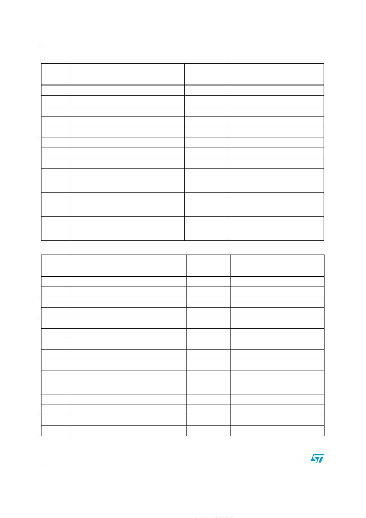
Table 2. Pin description: TQFP-64 (STA321MPL)
Pin
number
Type Name Description
1 5-V tolerant TTL input buffer PDM_CLK PDM I/F CLK
6 5-V tolerant TTL input buffer PDMIN_6 PDM input channel 6
7 5-V tolerant TTL input buffer PDMIN_5 PDM input channel 5
8 5-V tolerant TTL input buffer PDMIN_4 PDM input channel 4
9 5-V tolerant TTL input buffer PDMIN_3 PDM input channel 3
10 5-V tolerant TTL input buffer PDMIN_2 PDM input channel 2
11 5-V tolerant TTL input buffer PDMIN_1 PDM input channel 1
15 5-V tolerant TTL Schmitt trigger input buffer RESET Global reset
16 CMOS input buffer with pull-down PLLB Bypass phase-locked loop
18
Bidirectional buffer: 5-V tolerant TTL Schmitt
trigger input; 3.3-V capable 2 mA slew-rate
SDA Serial data (I
2
C)
controlled output
2
19 5-V tolerant TTL Schmitt trigger input buffer SCL Serial clock (I
C)
20 5-V tolerant TTL Schmitt trigger input buffer XTI Crystal oscillator input (clock input)
21 Analog pad FILTER_PLL PLL filter
22 3.3-V analog supply voltage VDDA PLL supply
23 Analog ground GNDA PLL ground
25 3.3-V capable TTL tristate 4 mA output buffer CKOUT Clock output
29 3.3-V capable TTL 2 mA output buffer OUT8B PWM channel 8 output B
30 3.3-V capable TTL 2 mA output buffer OUT8A PWM channel 8 output A
31 3.3-V capable TTL 2 mA output buffer OUT7B PWM channel 7 output B
32 3.3-V capable TTL 2 mA output buffer OUT7A PWM channel 7 output A
33 3.3-V capable TTL 2 mA output buffer OUT6B PWM channel 6 output B
34 3.3-V capable TTL 2 mA output buffer OUT6A PWM channel 6 output A
38 3.3-V capable TTL 2 mA output buffer OUT5B PWM channel 5 output B
39 3.3-V capable TTL 2 mA output buffer OUT5A PWM channel 5 output A
40 3.3-V capable TTL 2 mA output buffer OUT4B PWM channel 4 output B
41 3.3-V capable TTL 2 mA output buffer OUT4A PWM channel 4 output A
42 3.3-V capable TTL 2 mA output buffer OUT3B PWM channel 3 output B
43 3.3-V capable TTL 2 mA output buffer OUT3A PWM channel 3 output A
47 3.3-V capable TTL 2 mA output buffer OUT2B PWM channel 2 output B
48 3.3-V capable TTL 2 mA output buffer OUT2A PWM channel 2 output A
49 3.3-V capable TTL 2 mA output buffer OUT1B PWM channel 1 output B
50 3.3-V capable TTL 2 mA output buffer OUT1A PWM channel 1 output A
Doc ID 022647 Rev 1 9/50
Pin connections STA321MP
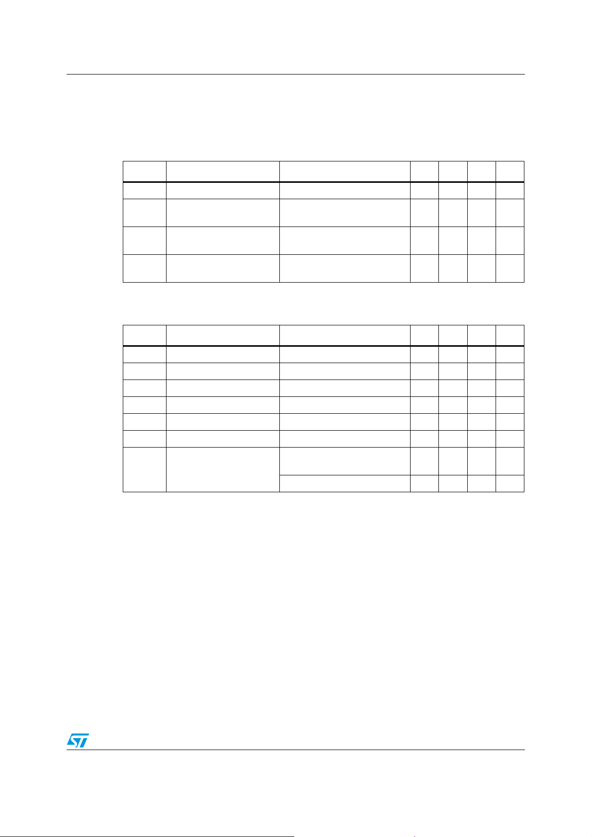
Table 2. Pin description: TQFP-64 (STA321MPL) (continued)
Pin
number
Type Name Description
51 3.3-V capable TTL 4 mA output buffer EAPD Ext. amp power-down
55 3.3-V capable TTL 2 mA output buffer BICKO Output serial clock
56 3.3-V capable TTL 2 mA output buffer LRCKO Output left/right clock
57 3.3-V capable TTL 2 mA output buffer SDO_12 Output serial data channels 1 & 2
58 3.3-V capable TTL 2 mA output buffer SDO_34 Output serial data channels 3 & 4
62 3.3-V capable TTL 2 mA output buffer SDO_56 Output serial data channels 5 & 6
63 3.3-V capable TTL 2 mA output buffer SDO_78 Output serial data channels 7 & 8
64 5-V tolerant TTL Schmitt trigger input buffer PWDN Device power-down
3,12,24,
28,35,
3.3-V digital supply voltage VDD3 3.3-V supply
44,52,59
2,4,13,
27,36,
Digital ground GND Ground
45,53,60
14,17,26,
37, 46,
NC Not connected
54,61,63
Table 3. Pin description: VFQFPN-56 (STA321MP)
Pin
number
Type Name Description
1 5-V tolerant TTL input buffer PDM_CLK PDM I/F CLK
5 5-V tolerant TTL input buffer PDMIN_6 PDM input channel 6
6 5-V tolerant TTL input buffer PDMIN_5 PDM input channel 5
7 5-V tolerant TTL input buffer PDMIN_4 PDM input channel 4
8 5-V tolerant TTL input buffer PDMIN_3 PDM input channel 3
9 5-V tolerant TTL input buffer PDMIN_2 PDM input channel 2
10 5-V tolerant TTL input buffer PDMIN_1 PDM input channel 1
13 5-V tolerant TTL Schmitt trigger input buffer RESET Global reset
14 CMOS input buffer with pull-down PLLB Bypass phase-locked loop
15
Bidirectional buffer: 5-V tolerant TTL Schmitt
trigger input; 3.3-V capable 2 mA slew-rate
SDA Serial data (I
2
C)
controlled output
2
16 5-V tolerant TTL Schmitt trigger input buffer SCL Serial clock (I
C)
17 5-V tolerant TTL Schmitt trigger input buffer XTI Crystal oscillator input (clock input)
18 Analog pad FILTER_PLL PLL filter
19 3.3-V analog supply voltage VDDA PLL supply
10/50 Doc ID 022647 Rev 1

STA321MP Pin connections
Table 3. Pin description: VFQFPN-56 (STA321MP) (continued)
Pin
number
20 Analog ground GNDA PLL ground
22 3.3-V capable TTL tristate 4 mA output buffer CKOUT Clock output
25 3.3-V capable TTL 2 mA output buffer OUT8B PWM channel 8 output B
26 3.3-V capable TTL 2 mA output buffer OUT8A PWM channel 8 output A
27 3.3-V capable TTL 2 mA output buffer OUT7B PWM channel 7 output B
28 3.3-V capable TTL 2 mA output buffer OUT7A PWM channel 7 output A
29 3.3-V capable TTL 2 mA output buffer OUT6B PWM channel 6 output B
30 3.3-V capable TTL 2 mA output buffer OUT6A PWM channel 6 output A
33 3.3-V capable TTL 2 mA output buffer OUT5B PWM channel 5 output B
34 3.3-V capable TTL 2 mA output buffer OUT5A PWM channel 5 output A
35 3.3-V capable TTL 2 mA output buffer OUT4B PWM channel 4 output B
36 3.3-V capable TTL 2 mA output buffer OUT4A PWM channel 4 output A
37 3.3-V capable TTL 2 mA output buffer OUT3B PWM channel 3 output B
38 3.3-V capable TTL 2 mA output buffer OUT3A PWM channel 3 output A
41 3.3-V capable TTL 2 mA output buffer OUT2B PWM channel 2 output B
42 3.3-V capable TTL 2 mA output buffer OUT2A PWM channel 2 output A
43 3.3-V capable TTL 2 mA output buffer OUT1B PWM channel 1 output B
Type Name Description
44 3.3-V capable TTL 2 mA output buffer OUT1A PWM channel 1 output A
45 3.3-V capable TTL 4 mA output buffer EAPD Ext. amp power-down
48 3.3-V capable TTL 2 mA output buffer BICKO Output serial clock
49 3.3-V capable TTL 2 mA output buffer LRCKO Output left/right clock
50 3.3-V capable TTL 2 mA output buffer SDO_12 Output serial data channels 1 & 2
51 3.3-V capable TTL 2 mA output buffer SDO_34 Output serial data channels 3 & 4
54 3.3-V capable TTL 2 mA output buffer SDO_56 Output serial data channels 5 & 6
55 3.3-V capable TTL 2 mA output buffer SDO_78 Output serial data channels 7 & 8
56 5-V tolerant TTL Schmitt trigger input buffer PWDN Device power-down
3,11,21,
24,31,
39,46,52
2,4,12,
23,32,
40,47,53
3.3-V digital supply voltage VDD3 3.3-V supply
Digital ground GND Ground
Doc ID 022647 Rev 1 11/50

Electrical specifications STA321MP
3 Electrical specifications
3.1 Absolute maximum ratings
Table 4. Absolute maximum ratings
Symbol Parameter Min Typ Max Unit
V
V
V
V
T
T
DD
DDA
i
o
stg
amb
3.3-V I/O power supply -0.5 4 V
3.3-V logic power supply -0.5 4 V
Voltage on input pins -0.5 VDD + 0.5 V
Voltage on output pins -0.5 VDD + 0.3 V
Storage temperature -40 150 °C
Ambient operating temperature -40 90 °C
3.2 Thermal data
Table 5. Thermal data
Symbol Parameter Min Typ Max Unit
R
thj-case
Thermal resistance, junction-case (thermal pad)
STA321MP
3.3 Recommended operating conditions
Table 6. Recommended operating conditions
Symbol Parameter Min Typ Max Unit
1.5 °C/W
V
V
T
DD
DDA
j
I/O power supply 3.0 3.6 V
Logic power supply 3.0 3.6 V
Operating junction temperature -40 125 °C
12/50 Doc ID 022647 Rev 1
STA321MP Electrical specifications
3.4 Electrical specifications
The following specifications are valid for VDD = 3.3 V ± 0.3 V, V
= 3.3 V ± 0.3 V and
DDA
Tamb = 0 to 70 °C, unless otherwise stated
Table 7. General interface electrical specifications
Symbol Parameter Conditions Min Typ Max Unit
I
il
I
ih
I
OZ
V
esd
1. The leakage currents are generally very small, < 1 nA. The values given here are maximum after an
electrostatic stress on the pin.
Table 8. DC electrical characteristics: 3.3-V buffers
Low-level input no pull-up Vi = 0 V 1
High-level input no
pull-down
Tristate output leakage
without pull-up/down
Electrostatic protection
(human body model)
V
= VDD 2μA
i
= VDD 2μA
V
i
Leakage < 1μA2000V
Symbol Parameter Conditions Min Typ Max Unit
V
IL
V
IH
V
ILhyst
V
IHhyst
V
hyst
V
ol
V
oh
Low-level input voltage 0.8 V
High-level input voltage 2.0 V
Low-level threshold Input falling 0.8 1.35 V
High-level threshold Input rising 1.3 2.0 V
Schmitt trigger hysteresis 0.3 0.8 V
Low-level output IoI = 100 µA 0.2 V
VDD-
0.2
High-level output
I
= -100 µA
oh
= -2 mA 2.4 V
I
oh
(1)
μA
V
Doc ID 022647 Rev 1 13/50

Pin description STA321MP
4 Pin description
PDM interface clock (PDM_CLK)
The clock to the PDM interface is provided on this pin and will be used by the device to
sample the digital microphone data. This clock must be used to clock both the interface and
the microphones. The clock frequency must not exceed the upper limit of the microphone’s
specific clock frequency (please refer to the datasheet of the specific microphone used).
PDM input channels (PDMIN_1/6)
Audio information enters the device through the PDM input channels. These input pins
receive the digital output signal from the microphones.
RESET
Driving this pin low turns off the outputs and returns all settings to their defaults.
I2C bus
The SDA and SCL pins operate per the Phillips I2C specification. See Section 5: I2C bus
operation.
Phase-locked loop (PLL)
The phase-locked loop section provides the system timing signals and CKOUT.
Clock output (CKOUT)
System synchronization and master clocks are provided by CKOUT. This clock can be
conveniently divided and then used to clock both the PDM interface and the microphones.
Please refer to Figure 6.
PWM outputs (OUT1 through OUT8)
The PWM outputs provide the input signal for the power devices.
Serial data out (SDO_12, SDO_34, SDO_56, SDO_78)
These are the outputs for audio information. Six different formats are available including I2S,
left- or right-justified, LSB or MSB first, with word widths of 16, 18, 20 and 24 bits.
Device power-down (PWDN)
Pulling PWDN low begins the power-down sequence which puts the STA321MP into a
low-power state. EAPD (pin 45 of the VFQFN-56 or pin 51 of the TQFP-64) goes low
approximately 30 ms later.
14/50 Doc ID 022647 Rev 1

STA321MP I2C bus operation
5 I2C bus operation
The STA321MP supports the I2C protocol via the input ports SCL and SDA_IN (master to
slave) and the output port SDA_OUT (slave to master).
This protocol defines any device that sends data on to the bus as a transmitter and any
device that reads the data as a receiver.
The device that controls the data transfer is known as the master and the other as the slave.
The master always starts the transfer and provides the serial clock for synchronization. The
STA321MP is always a slave device in all of its communications.
5.1 Communication protocol
5.1.1 Data transition or change
Data changes on the SDA line must only occur when the SCL clock is low. SDA transition
while the clock is high is used to identify a START or STOP condition.
5.1.2 Start condition
START is identified by a high to low transition of the data bus SDA signal while the clock
signal SCL is stable in the high state. A START condition must precede any command for
data transfer.
5.1.3 Stop condition
STOP is identified by a low to high transition of the data bus SDA signal while the clock
signal SCL is stable in the high state. A STOP condition terminates communication between
STA321MP and the bus master.
5.1.4 Data input
During the data input the STA321MP samples the SDA signal on the rising edge of clock
SCL.
For correct device operation the SDA signal must be stable during the rising edge of the
clock and the data can change only when the SCL line is low.
5.2 Device addressing
To start communication between the master and the Omega FFX core, the master must
initiate with a start condition. Following this, the master sends 8 bits to the SDA line (MSB
first) corresponding to the device select address and read or write mode.
The 7 most significant bits are the device address identifiers, corresponding to the I
definition. In the STA321MP the I
SA port configuration, 0x40 or 0100000x when SA = 0, and 0x42 or 0100001x when SA = 1.
th
The 8
0 for write mode. After a START condition the STA321MP identifies on the bus the device
bit (LSB) identifies a read or write operation RW, this bit is set to 1 in read mode and
2
C interface has two device addresses depending on the
2
C bus
Doc ID 022647 Rev 1 15/50

I2C bus operation STA321MP
A
A
A
A
A
A
A
address and if a match is found, it acknowledges the identification on SDA bus during the
th
9
-bit time. The byte following the device identification byte is the internal space address.
5.3 Write operation
Following the START condition the master sends a device select code with the RW bit set
to 0. The STA321MP acknowledges this and then waits for the byte of internal address.
After receiving the internal byte address the STA321MP again responds with an
acknowledgement.
5.3.1 Byte write
In the byte write mode the master sends one data byte, which is acknowledged by the FFX
core. The master then terminates the transfer by generating a STOP condition.
5.3.2 Multi-byte write
The multi-byte write modes can start from any internal address. The master generating a
STOP condition terminates the transfer.
Figure 4. Write mode sequence
BYTE
WRITE
MULTIBYTE
WRITE
DEV-ADDR
START
DEV-ADDR
START
ACK
SUB-ADDR
RW
ACK
SUB-ADDR
RW
Figure 5. Read mode sequence
CURRENT
ADDRESS
READ
RANDOM
ADDRESS
READ
SEQUENTIAL
CURRENT
READ
SEQUENTIAL
RANDOM
READ
START
START
START
START
DEV-ADDR
DEV-ADDR
DEV-ADDR
DEV-ADDR
RW=
HIGH
ACK
RW
ACK
RW
ACK
ACK
RW
NO ACK
DATA
ACK
SUB-ADDR
ACK
DATA
ACK
SUB-ADDR
STOP
DATA
DEV-ADDR
DEV-ADDR
ACK
ACK
DATA IN
DATA IN
CK
STOP
CK
DATA IN
CK
STOP
AM045330v1
CK
WRTRATS
ACK
CK
WRTRATS
DATA
DATA
DATA
NO ACK
NO ACK
STOP
STOP
CK
DATA
CK NO ACK
DATA
STOP
AM045331v1
16/50 Doc ID 022647 Rev 1

STA321MP Application reference schematic
6 Application reference schematic
Figure 6. Reference schematic for STA321MP-based application
3.3V
Digital Microphones
VDD
LR
GND
VDD
LR
GND
VDD
LR
GND
VDD
LR
GND
VDD
LR
GND
VDD
LR
GND
CK
DATA
CK
DATA
CK
DATA
CK
DATA
CK
DATA
CK
DATA
External Clock
11.2896 MHz
XTI
PDM_IN1
PDM_IN2
PDM_IN3
PDM_IN4
PDM_IN5
PDM_IN6
Dual Flip/Flop
CK divider
PDM_CLK
Control Interface
SCL
SDA
RESET
CKOUT
OUTxA
PLL_BYPASS
OUTxB
FILTER_PLL
BICKO
LRCKO
SDO_12
SDO_34
SDO_56
VDD3
GND
100pF
3.3K
1nF
I2S
Receiver/
Processor
or
Audio
Precision
3.3V
100nF
Analog
Output Interface
AM045332v1
Figure 7. Application circuit
Doc ID 022647 Rev 1 17/50

Registers STA321MP
7 Registers
7.1 Register summary
Table 9. Register summary
Addr Name D7 D6 D5 D4 D3 D2 D1 D0
Configuration
0x00 CONFA COS1 COS0 DSPB IR1 IR0 MCS2 MCS1 MCS0
0x01 ConfB SAIFB SAI3 SAI2 SAI1 SAI0
0x02 ConfC SAOFB SAO3 SAO2 SAO1 SAO0
0x03 ConfD MPC CSZ4 CSZ3 CSZ2 CSZ1 CSZ0 OM1 OM0
0x04 ConfE C8BO C7BO C6BO C5BO C4BO C3BO C2BO C1BO
0x05 ConfF PWMS2 PWMS1 PWMS0 BQL PSL DEMP DRC HPB
0x06 ConfG MPCV DCCV HPE AM2E AME COD SID PWMD
0x07 ConfH ECLE LDTE BCLE IDE ZDE SVE ZCE NSBW
0x08 ConfI EAPD PSCE
Volume c o n t r o l
0x09 MMUTE MMUTE
0x0A Mvol MV7 MV6 MV5 MV4 MV3 MV2 MV1 MV0
0x0B C1Vol C1V7 C1V6 C1V5 C1V4 C1V3 C1V2 C1V1 C1V0
0x0C C2Vol C2V7 C2V6 C2V5 C2V4 C2V3 C2V2 C2V1 C2V0
0x0D C3Vol C3V7 C3V6 C3V5 C3V4 C3V3 C3V2 C3V1 C3V0
0x0E C4Vol C4V7 C4V6 C4V5 C4V4 C4V3 C4V2 C4V1 C4V0
0x0F C5Vol C5V7 C5V6 C5V5 C5V4 C5V3 C5V2 C5V1 C5V0
0x10 C6Vol C6V7 C6V6 C6V5 C6V4 C6V3 C6V2 C6V1 C6V0
0x11 C7Vol C7V7 C7V6 C7V5 C7V4 C7V3 C7V2 C7V1 C7V0
0x12 C8Vol C8V7 C8V6 C8V5 C8V4 C8V3 C8V2 C8V1 C8V0
0x13 C1VTMB C1M C1VBP C1VT4 C1VT3 C1VT2 C1VT1 C1VT0
0x14 C2VTMB C2M C2VBP C2VT4 C2VT3 C2VT2 C2VT1 C2VT0
0x15 C3VTMB C3M C3VBP C3VT4 C3VT3 C3VT2 C3VT1 C3VT0
0x16 C4VTMB C4M C4VBP C4VT4 C4VT3 C4VT2 C4VT1 C4VT0
0x17 C5VTMB C5M C5VBP C5VT4 C5VT3 C5VT2 C5VT1 C5VT0
0x18 C6VTMB C6M C6VBP C6VT4 C6VT3 C6VT2 C6VT1 C6VT0
0x19 C7VTMB C7M C7VBP C7VT4 C7VT3 C7VT2 C7VT1 C7VT0
0x1A C8VTMB C8M C8VBP C8VT4 C8VT3 C8VT2 C8VT1 C8VT0
18/50 Doc ID 022647 Rev 1

STA321MP Registers
Table 9. Register summary (continued)
Addr Name D7 D6 D5 D4 D3 D2 D1 D0
Input mapping
0x1B C12im C2IM2 C2IM1 C2IM0 C1IM2 C1IM1 C1IM0
0x1C C34im C4IM2 C4IM1 C4IM0 C3IM2 C3IM1 C3IM0
0x1D C56im C6IM2 C6IM1 C6IM0 C5IM2 C5IM1 C5IM0
0x1E C78im C8IM2 C8IM1 C8IM0 C7IM2 C7IM1 C7IM0
Processing loop
0x28 BQlp C8BLP C7BLP C6BLP C5BLP C4BLP C3BLP C2BLP C1BLP
0x29 MXlp C8MXLP C7MXLP C6MXLP C5MXLP C4MXLP C3MXLP C2MXLP C1MXLP
Processing bypass
0x2A EQbp C8EQBP C7EQBP C6EQBP
0x2B ToneBP C8TCB C7TCB C6TCB C5TCB C4TCB C3TCB C2TCB C1TCB
Tone contro l
0x2C Tone TTC3 TTC2 TTC1 TTC0 BTC3 BTC2 BTC1 BTC0
PWM output timing
0x33 C12ot C2OT2 C2OT1 C2OT0 C1OT2 C1OT1 C1OT0
0x34 C34ot C4OT2 C4OT1 C4OT0 C3OT2 C3OT1 C3OT0
0x35 C56ot C6OT2 C6OT1 C6OT0 C5OT2 C5OT1 C5OT0
0x36 C78ot C8OT2 C8OT1 C8OT0 C7OT2 C7OT1 C7OT0
2
I
S output channel mapping
0x37 C12om C2OM2 C2OM1 C2OM0 C1OM2 C1OM1 C1OM0
0x38 C34om C4OM2 C4OM1 C4OM0 C3OM2 C3OM1 C3OM0
0x39 C56om C6OM2 C6OM1 C6OM0 C5OM2 C5OM1 C5OM0
0x3A C78om C8OM2 C8OM1 C8OM0 C7OM2 C7OM1 C7OM0
User-defined coefficient RAM
0x3B Cfaddr1 CFA9 CFA8
0x3 C Cfadd r2 C FA7 C FA6 CFA5 C FA4 CFA3 CFA2 CFA1 C FA0
0x3D B1cf1 C1B23 C1B22 C1B21 C1B20 C1B19 C1B18 C1B17 C1B16
0x3E B1cf2 C1B15 C1B14 C1B13 C1B12 C1B11 C1B10 C1B9 C1B8
C5EQBP
C4EQBP C3EQBP C2EQBP C1EQBP
0x3F B1cf3 C1B7 C1B6 C1B5 C1B4 C1B3 C1B2 C1B1 C1B0
0x40 B2cf1 C2B23 C2B22 C2B21 C2B20 C2B19 C2B18 C2B17 C2B16
0x41 B2cf2 C2B15 C2B14 C2B13 C2B12 C2B11 C2B10 C2B9 C2B8
0x42 B2cf3 C2B7 C2B6 C2B5 C2B4 C2B3 C2B2 C2B1 C2B0
0x43 A1cf1 C3B23 C3B22 C3B21 C3B20 C3B19 C3B18 C3B17 C3B16
Doc ID 022647 Rev 1 19/50

Registers STA321MP
Table 9. Register summary (continued)
Addr Name D7 D6 D5 D4 D3 D2 D1 D0
0x44 A1cf2 C3B15 C3B14 C3B13 C3B12 C3B11 C3B10 C3B9 C3B8
0x45 A1cf3 C3B7 C3B6 C3B5 C3B4 C3B3 C3B2 C3B1 C3B0
0x46 A2cf1 C4B23 C4B22 C4B21 C4B20 C4B19 C4B18 C4B17 C4B16
0x47 A2cf2 C4B15 C4B14 C4B13 C4B12 C4B11 C4B10 C4B9 C4B8
0x48 A2cf3 C4B7 C4B6 C4B5 C4B4 C4B3 C4B2 C4B1 C4B0
0x49 B0cf1 C5B23 C5B22 C5B21 C5B20 C5B19 C5B18 C5B17 C5B16
0x4A B0cf2 C5B15 C5B14 C5B13 C5B12 C5B11 C5B10 C5B9 C5B8
0x4B B0cf3 C5B7 C5B6 C5B5 C5B4 C5B3 C5B2 C5B1 C5B0
0x4C Cfud WA W1
0x4D MPCC1 MPCC15 MPCC14 MPCC13
0x4E MPCC2 MPCC7 MPCC6 MPCC5 MPCC4 MPCC3 MPCC2 MPCC1 MPCC0
0x4F DCC1 DCC15 DCC14 DCC13 DCC12 DCC11 DCC10 DCC9 DCC8
0x50 DCC2 DCC7 DCC6 DCC5 DCC4 DCC3 DCC2 DCC1 DCC0
0x51 PSC1 RCV11 RCV10 RCV9 RCV8 RCV7 RCV6 RCV5 RCV4
0x52 PSC2 RCV3 RCV2 RCV1 RCV0 CNV11 CNV10 CNV9 CNV8
MPCC12
MPCC11 MPCC10 MPCC9 MPCC8
0x53 PSC3 CNV7 CNV6 CNV5 CNV4 CNV3 CNV2 CNV1 CNV0
20/50 Doc ID 022647 Rev 1

STA321MP Registers
7.2 Register description
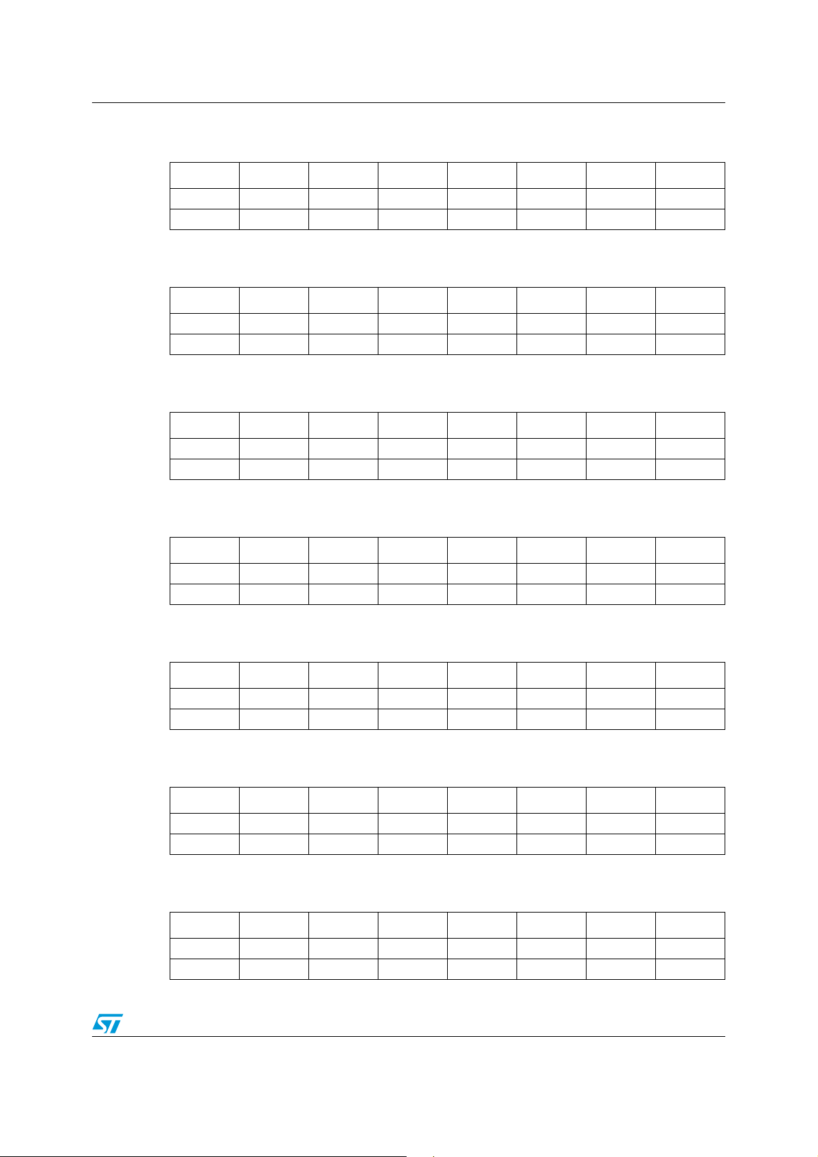
7.2.1 Configuration register A (0x00)
D7 D6 D5 D4 D3 D2 D1 D0
COS1 COS0 DSPB IR1 IR0 MCS2 MCS1 MCS0
10000011
Bit RW RST Name Description
0RW1 MCS0
1RW1 MCS1
2RW0 MCS2
Master clock select: selects the ratio between the
input sampling frequency (PDM I/FCLK) and the
input clock(XTI).
The STA321MP supports a sampling rate of 2.8224 MHz. Therefore the internal clock is:
● 90.3168 MHz for the respective sampling frequency
The external clock frequency provided to the XTI pin must be a multiple of the input
sampling frequency (fs). The relationship between the input clock and the input sampling
rate is determined by both the MCSn and the IRn (input rate) register bits. The MCSn bits
determine the PLL factor generating the internal clock and the IRn bits determine the
oversampling ratio used internally.
Input sampling rate
fs (kHz)
IR
1XX 011 010 001 000
MCS[2:0]
PDM I/F 2822.4 11 2 * fs 4 * fs 6 * fs 8 * fs 10 * fs
Interpolation ratio select
Bit RW RST Name Description
3 RW 0 IR0 Interpolation ratio select: selects the internal
4RW 0 IR1
interpolation ratio based on the input sampling
frequency
The STA321MP has variable interpolation (oversampling) settings such that internal
processing and FFX output rates remain consistent. The first processing block interpolates
by either 4 times, 2 times, or 1 time (pass-through).
The oversampling ratio of this interpolation is determined by the IR bits.
I
IR[1,0]
Input sampling rate
Fs (kHz)
11 2822.4 PDM CLK to 176.4 kHz conversion
Doc ID 022647 Rev 1 21/50
st
stage interpolation ratio
1

Registers STA321MP
Bit RW RST Name Description
DSP bypass bit:
0 RW 0 DSPB
0: normal operation
1: bypass of biquad and bass/treble functions
Setting the DSPB bit bypasses the biquad function of the FFX core.
COS[1,0] CKOUT frequency
00 PLL output
01 PLL output / 4
10 PLL output / 8
11 PLL output / 16
Application example:
● External clock: XTI=11.2896 MHz
● COS[1,0] = 10: CKOUT= 90.3168 MHz / 8 = 11.2896 MHz
● External Dual Flip Flop PDM I/F = CKOUT/4 = 2.8224 MHz, also provided to the
microphones
● MCS[2:0]= 011: XTI /Fs = 4
22/50 Doc ID 022647 Rev 1

STA321MP Registers
7.2.2 Configuration register C (0x02) - serial output formats
D7 D6 D5 D4 D3 D2 D1 D0
SAOFB SAO3 SAO2 SAIO SAO0
00000
Bit RW RST Name Description
0RW 0 SAO0
1RW 0 SAO1
2RW 0 SAO2
3RW 0 SAO3
The STA321MP features a serial audio output interface that consists of 8 channels.
The serial audio output acts as a master with an output sampling frequency of 176.4 kHz.
The output serial format can be selected independently from the input format and is done
via the SAO and SAOFB bits.
Bit RW RST Name Description
Serial audio output interface format: determines the
interface format of the output serial digital audio
interface.
Determines MSB or LSB first for all SAO formats:
4RW 0 SAOFB
0: MSB first
1: LSB first
BICKI = BICKO SAO[3:0] Interface data format
2
0111 I
S data
32 * fs
1111 Left/right-justified 16-bit data
1110 I
2
S data
0001 Left-justified data
1010 Right-justified 24-bit data
48 * fs
1011 Right-justified 20-bit data
1100 Right-justified 18-bit data
1101 Right-justified 16-bit data
0000 I
2
S data
0001 Left-justified data
0010 Right-justified 24-bit data
64 * fs
0011 Right-justified 20-bit data
0100 Right-justified 18-bit data
0101 Right-justified 16-bit data
Doc ID 022647 Rev 1 23/50

Registers STA321MP
7.2.3 Configuration register E (0x04)
D7 D6 D5 D4 D3 D2 D1 D0
C8BO C7BO C6BO C5BO C4BO C3BO C2BO C1BO
00000000
Bit RW RST Name Description
0RW 0 C1BO
1RW 0 C2BO
2RW 0 C3BO
3RW 0 C4BO
4RW 0 C5BO
5RW 0 C6BO
6RW 0 C7BO
7RW 0 C8BO
Each individual channel output can be set to output a binary PWM stream. In this mode
output A of a channel will be considered the positive output and output B is the negative
inverse.
Channels 1, 2, 3, 4, 5, 6, 7, and 8 binary output
mode enable bits. A setting of 0 indicates ordinary
FFX tristate output. A setting of 1 indicates binary
output mode.
7.2.4 Configuration register F (0x05)
D7 D6 D5 D4 D3 D2 D1 D0
PWMS2 PWMS1 PWMS0 BQL PSL DEMP DRC HPB
00000000
Bit RW RST Name Description
0RW 0 HPB
The STA321MP features an internal digital high-pass filter for the purpose of AC coupling.
The purpose of this filter is to prevent DC signals from passing through an FFX amplifier. DC
signals can cause speaker damage.
If HPB = 1, then the filter that the high-pass filter utilizes is made available as userprogrammable biquad#1.
Bit RW RST Name Description
1 RW 0 DRC
Both limiters can be used in one of two ways, anti-clipping or dynamic range compression.
When used in anti-clipping mode, the limiter threshold values are constant and dependent
on the limiter settings.
High-pass filter bypass bit: a setting of 1 bypasses
the internal AC coupling digital high-pass filter
Dynamic range compression/anti-clipping
0: limiters act in anti-clipping mode
1: limiters act in dynamic range compression mode
24/50 Doc ID 022647 Rev 1

STA321MP Registers
In dynamic range compression mode the limiter threshold values vary with the volume
settings, allowing a nighttime listening mode that provides a reduction in the dynamic range
regardless of the volume level.
Bit RW RST Name Description
De-emphasis:
2RW 0 DEMP
0: no de-emphasis
1: de-emphasis
By setting this bit to one, de-emphasis will be implemented on all channels. When this is
used it takes the place of biquad #7 in each channel and any coefficients using biquad #1
will be ignored. The DSPB (DSP bypass) bit must be set to 0 for de-emphasis to function.
Bit RW RST Name Description
Post-scale link:
3 RW 0 PSL
0: each channel uses individual post-scale values
1: each channel uses channel 1 post-scale values
Post-scale functionality can be used for power-supply error correction. For multi-channel
applications running off the same power-supply, the post-scale values can be linked to the
value of channel 1 for ease of use and in order to update the values faster.
Bit RW RST Name Description
Biquad link:
4RW 0 BQL
0: each channel uses coefficient values
1: each channel uses channel 1 coefficient values
For ease of use, all channels can use the biquad coefficients loaded into the channel 1
Coefficient RAM space by setting the BQL bit to 1. Therefore, any EQ updates only have to
be performed once.
Bit RW RST Name Description
7:5 RW 00 PWMS[2:0] PWM speed selection
PWMS[1:0] PWM output speed
000 Normal speed (384 kHz) (all channels)
001 Half-speed (192 kHz) (all channels)
010 Double-speed (768 kHz) (all channels)
011 Normal speed (channels 1-6), double-speed (channels 7-8)
100 Odd speed (341.3 kHz) (all channels)
Doc ID 022647 Rev 1 25/50

Registers STA321MP
7.2.5 Configuration register G (0x06)
D7 D6 D5 D4 D3 D2 D1 D0
MPCV DCCV HPE AM2E AME COD SID PWMD
00000000
Bit RW RST Name Description
PWM output disable:
0RW0 PWMD
1RW0 SID
2RW0 COD
Bit RW RST Name Description
0: PWM output normal
1: no PWM output
2
Serial interface (I
2
S output normal
0: I
S out) disable:
1: no I2S output
Clock output disable:
0: clock output normal
1: no clock output
AM mode enable:
3RW 0 AME
0: normal FFX operation
1: AM reduction mode FFX operation
The STA321MP features an FFX processing mode that minimizes the amount of noise
generated in the frequency range of AM radio. This mode is intended for use when FFX is
operating in a device with an active AM tuner. The SNR of the FFX processing is reduced to
~83 dB in this mode, which is still greater than the SNR of AM radio.
Bit RW RST Name Description
AM2 mode enable:
4RW 0 AM2E
0: normal FFX operation
1: AM2 reduction mode FFX operation
The STA321MP features two FFX processing modes that minimize the amount of noise
generated in the frequency range of AM radio. This second mode is intended for use when
FFX is operating in a device with an active AM tuner. This mode eliminates the noiseshaper.
Bit RW RST Name Description
FFX headphone enable:
5RW 0 HPE
0: channels 7 and 8 normal FFX operation
1: channels 7 and 8 headphone operation
Channels 7 and 8 can be configured to be processed and output in such a manner that
headphones can be driven using an appropriate output device. This signal is a differential
3-wire drive called FFX headphone.
26/50 Doc ID 022647 Rev 1

STA321MP Registers
Bit RW RST Name Description
Distortion compensation variable enable:
6 RW 0 DCCV
0: uses preset DC coefficient
1: uses DCC coefficient
Bit RW RST Name Description
Max power correction variable:
7RW 0 MPCV
0: use standard MPC coefficient
1: use MPCC bits for MPC coefficient
7.2.6 Configuration register H (0x07)
D7 D6 D5 D4 D3 D2 D1 D0
ECLE LDTE BCLE IDE ZDE SVE ZCE NSBW
01111110
Bit RW RST Name Description
Noise-shaper bandwidth selection:
0 RW 0 NSBW
1: 3
rd
order NS
0: 4th order NS
Bit RW RST Name Description
Zero-crossing volume enable:
1RW1 ZCE
1: volume adjustments will only occur at digital zerocrossings
0: volume adjustments will occur immediately
The ZCE bit enables zero-crossing volume adjustments. When volume is adjusted on digital
zero-crossings, no clicks will be audible.
Bit RW RST Name Description
Soft volume enable:
2RW1 SVE
Bit RW RST Name Description
3RW1 ZDE
1: volume adjustments use soft volume
0: volume adjustments occur immediately
Zero-detect mute enable: setting of 1 enables the
automatic zero-detect mute
Setting the ZDE bit enables the zero-detect automatic mute. The zero-detect circuit looks at
the input data to each processing channel after the channel-mapping block. If any channel
receives 2048 consecutive zero value samples (regardless of fs), then that individual
channel is muted if this function is enabled.
Doc ID 022647 Rev 1 27/50

Registers STA321MP
Bit RW RST Name Description
4RW 1 IDE
Invalid input detect mute enable:
1: enable the automatic invalid input detect mute
Setting the IDE bit enables this function, which looks at the input I2S data and will
automatically mute if the signals are perceived as invalid.
Bit RW RST Name Description
5 RW 1 BCLE Binary output mode clock loss detection enable
The BCLE bit detects loss of input MCLK in binary mode and will output 50% duty cycle.
Bit RW RST Name Description
6 RW 1 LDTE LRCLK double trigger protection enable
The LDTE bit actively prevents double triggering of LRCLK.
Bit RW RST Name Description
7 RW 1 ECLE Auto EAPD on clock loss
The ECLE bit controls the device power down signal (EAPD) on clock loss detection. This
function is enabled by default. It is strongly recommended to avoid spurious noise during the
on-off sequence. The STA321MP has the ECLE bit set to 0.
7.2.7 Configuration register I (0x08)
D7 D6 D5 D4 D3 D2 D1 D0
EAPD PSCE
0 0
This feature utilizes an ADC on SDI78 that provides power supply ripple information for
correction. Registers PSC1, PSC2, PSC3 are utilized in this mode.
Bit RW RST Name Description
0 RW 0 PSCE
Bit RW RST Name Description
7 RW 0 EAPD
Power supply ripple correction enable:
0: normal operation
1: PSCorrect operation
External amplifier power down:
0: external power stage power-down active
1: normal operation
28/50 Doc ID 022647 Rev 1

STA321MP Registers
7.2.8 Master mute register (0x09)
D7 D6 D5 D4 D3 D2 D1 D0
MMUTE
0
7.2.9 Master volume register (0x0A)
D7 D6 D5 D4 D3 D2 D1 D0
MV7 MV6 MV5 MV4 MV3 MV2 MV1 MV0
11111111
Note: The value of the volume derived from MVOL is dependent on the AMV AutoMode volume
settings.
7.2.10 Channel 1 volume (0x0B)
D7 D6 D5 D4 D3 D2 D1 D0
C1V7 C1V6 C1V5 C1V4 C1V3 C1V2 C1V1 C1V0
01100000
7.2.11 Channel 2 volume (0x0C)
D7 D6 D5 D4 D3 D2 D1 D0
C2V7 C2V6 C2V5 C2V4 C2V3 C2V2 C2V1 C2V0
01100000
7.2.12 Channel 3 volume (0x0D)
D7 D6 D5 D4 D3 D2 D1 D0
C3V7 C3V6 C3V5 C3V4 C3V3 C3V2 C3V1 C3V0
01100000
7.2.13 Channel 4 volume (0x0E)
D7 D6 D5 D4 D3 D2 D1 D0
C4V7 C4V6 C4V5 C4V4 C4V3 C4V2 C4V1 C4V0
01100000
Doc ID 022647 Rev 1 29/50

Registers STA321MP
7.2.14 Channel 5 volume (0x0F)
D7 D6 D5 D4 D3 D2 D1 D0
C5V7 C5V6 C5V5 C5V4 C5V3 C5V2 C5V1 C5V0
01100000
7.2.15 Channel 6 volume (0x10)
D7 D6 D5 D4 D3 D2 D1 D0
C6V7 C6V6 C6V5 C6V4 C6V3 C6V2 C6V1 C6V0
01100000
7.2.16 Channel 7 volume (0x11)
D7 D6 D5 D4 D3 D2 D1 D0
C7V7 C7V6 C7V5 C7V4 C7V3 C7V2 C7V1 C7V0
01100000
7.2.17 Channel 8 volume (0x12)
D7 D6 D5 D4 D3 D2 D1 D0
C8V7 C8V6 C8V5 C8V4 C8V3 C8V2 C8V1 C8V0
01100000
7.2.18 Channel 1 volume trim, mute, bypass (0x13)
D7 D6 D5 D4 D3 D2 D1 D0
C1M C1VBP C1VT4 C1VT3 C1VT2 C1VT1 C1VT0
00010000
7.2.19 Channel 2 volume trim, mute, bypass (0x14)
D7 D6 D5 D4 D3 D2 D1 D0
C2M C2VBP C2VT4 C2VT3 C2VT2 C2VT1 C2VT0
00010000
7.2.20 Channel 3 volume trim, mute, bypass (0x15)
D7 D6 D5 D4 D3 D2 D1 D0
C3M C3VBP C3VT4 C3VT3 C3VT2 C3VT1 C3VT0
00010000
30/50 Doc ID 022647 Rev 1

STA321MP Registers
7.2.21 Channel 4 volume trim, mute, bypass (0x16)
D7 D6 D5 D4 D3 D2 D1 D0
C4M C4VBP C4VT4 C4VT3 C4VT2 C4VT1 C4VT0
00010000
7.2.22 Channel 5 volume trim, mute, bypass (0x17)
D7 D6 D5 D4 D3 D2 D1 D0
C5M C5VBP C5VT4 C5VT3 C5VT2 C5VT1 C5VT0
00010000
7.2.23 Channel 6 volume trim, mute, bypass (0x18)
D7 D6 D5 D4 D3 D2 D1 D0
C6M C6VBP C6VT4 C6VT3 C6VT2 C6VT1 C6VT0
00010000
7.2.24 Channel 7 volume trim, mute, bypass (0x19)
D7 D6 D5 D4 D3 D2 D1 D0
C7M C7VBP C7VT4 C7VT3 C7VT2 C7VT1 C7VT0
00010000
7.2.25 Channel 8 volume trim, mute, bypass (0x1A)
D7 D6 D5 D4 D3 D2 D1 D0
C8M C8VBP C8VT4 C8VT3 C8VT2 C8VT1 C8VT0
00010000
The volume structure of the STA321MP consists of individual volume registers for each
channel and a master volume register that provides an offset to each channel’s volume
setting. There is also an additional offset for each channel called the channel volume trim.
The individual channel volumes are adjustable in 0.5 dB steps from +48 dB to -78 dB. As an
example, if C5V = 0xXX or +XXX dB and MV = 0xXX or -XX dB, then the total gain for
channel 5 = XX dB. The channel volume trim is adjustable independently on each channel
from -10 dB to +10 dB in 1 dB steps. The master mute when set to 1 will mute all channels
at once, whereas the individual channel mutes (CnM) will mute only that channel. Both the
master mute and the channel mutes provide a "soft mute" with the volume ramping down to
mute in 8192 samples from the maximum volume setting at the internal processing rate
(~192 kHz). A "hard mute" can be obtained by commanding a value of 0xFF (255) to any
channel volume register or the master volume register. When volume offsets are provided
via the master volume register, any channel whose total volume is less than -91 dB will be
muted. All changes in volume take place at zero-crossings when ZCE = 1 (configuration
register H) on a per-channel basis as this creates the smoothest possible volume
Doc ID 022647 Rev 1 31/50

Registers STA321MP
transitions. When ZCE = 0, volume updates occur immediately. Each channel also contains
an individual channel volume bypass. If a particular channel has volume bypassed via the
CnVBP = 1 register, then only the channel volume setting for that particular channel affects
the volume setting, the master volume setting will not affect that channel. Each channel also
contains a channel mute. If CnM = 1 a soft mute is performed on that channel.
MV[7:0] Volume offset from channel value
0x00 0 dB
0x01 -0.5 dB
0x02 -1 dB
……
0x4C -38 dB
……
0xFE -127 dB
0xFF Hardware channel mute
CnV[7:0] Volume
0x00 +48 dB
0x01 +47.5 dB
0x02 +47 dB
……
0x5F +0.5 dB
0x60 0 dB
0x61 -0.5 dB
……
0xFE -79.5 dB
0xFF Hardware channel mute
CnVT[4:0] Volume
0x00 to 0x06 +10 dB
0x07 +9 dB
……
0x0F +1 dB
0x10 0 dB
0x11 -1 dB
……
0x19 -9 dB
0x1A to 0x1F -10 dB
32/50 Doc ID 022647 Rev 1

STA321MP Registers
7.2.26 Channel input mapping channels 1 and 2 (0x1B)
D7 D6 D5 D4 D3 D2 D1 D0
C2IM2 C2IM1 C2IM0 C1IM2 C1IM1 C1IM0
001 000
7.2.27 Channel input mapping channels 3 and 4 (0x1C)
D7 D6 D5 D4 D3 D2 D1 D0
C4IM2 C4IM1 C4IM0 C3IM2 C3IM1 C3IM0
011 010
7.2.28 Channel input mapping channels 5 and 6 (0x1D)
D7 D6 D5 D4 D3 D2 D1 D0
C6IM2 C6IM1 C6IM0 C5IM2 C5IM1 C5IM0
101 100
7.2.29 Channel input mapping channels 7 and 8 (0x1E)
D7 D6 D5 D4 D3 D2 D1 D0
C8IM2 C8M1 C8IM0 C7IM2 C7IM1 C7IM0
111 110
Each channel received via I2S can be mapped to any internal processing channel via the
channel input mapping registers. This allows for flexibility in processing, simplifies output
stage designs, and enables the ability to perform crossovers. The default settings of these
registers map each I
000 Channel 1
001 Channel 2
010 Channel 3
011 Channel 4
100 Channel 5
101 Channel 6
110 Channel 7
111 Channel 8
2
S input channel to its corresponding processing channel.
CnIM[2:0] Serial input from
Doc ID 022647 Rev 1 33/50

Registers STA321MP
7.2.30 Biquad internal channel loop-through (0x28)
D7 D6 D5 D4 D3 D2 D1 D0
C8BLP C7BLP C6BLP C5BLP C4BLP C3BLP C2BLP C1BLP
00000000
Each internal processing channel can receive two possible inputs at the input to the biquad
block. The input can come either from the output of that channel’s MIX#1 engine or from the
output of the bass/treble (biquad #10) of the previous channel. In this scenario, channel 1
receives channel 8. This enables the use of more than 10 biquads on any given channel at
the loss of the number of separate internal processing channels.
Bit RW RST Name Description
For n = 1 to 8:
0: input from channel n MIX#1 engine output - normal
7:0 RW 0 CnBLP
operation
1: input from channel (n - 1) biquad #10 output - loop
operation
34/50 Doc ID 022647 Rev 1

STA321MP Registers
7.2.31 Mix internal channel loop-through (0x29)
D7 D6 D5 D4 D3 D2 D1 D0
C8MXLP C7MXLP C6MXLP C5MXLP C4MXLP C3MXLP C2MXLP C1MXLP
00000000
Each internal processing channel can receive two possible sets of inputs at the inputs to the
Mix#1 block. The inputs can come from the outputs of the interpolation block as normally
occurs (CnMXLP = 0) or they can come from the outputs of the Mix#2 block. This enables
the use of additional filtering after the second mix block at the expense of losing this
processing capability on the channel.
Bit RW RST Name Description
For n = 1 to 8:
0: inputs to channel n MIX#1 engine from interpolation
7:0 RW 0 CnMXLP
outputs - normal operation
1: inputs to channel n MIX#1 engine from MIX#2 engine
outputs - loop operation
7.2.32 EQ bypass (0x2A)
D7 D6 D5 D4 D3 D2 D1 D0
C8EQBP C7EQBP C6EQBP C5EQBP C4EQCBP C3EQBP C2EQBP C1EQBP
00000000
EQ control can be bypassed on a per-channel basis. If EQ control is bypassed on a given
channel the prescale and all 10 filters (high-pass, biquads, de-emphasis, bass management
cross-over, bass, treble in any combination) are bypassed for that channel.
Bit RW RST Name Description
7:0 RW 0 CnEQBP
7.2.33 Tone control bypass (0x2B)
D7 D6 D5 D4 D3 D2 D1 D0
C8TCB C7TCB C6TCB C5TCB C4TCB C3TCB C2TCB C1TCB
00000000
Tone control (bass/treble) can be bypassed on a per-channel basis. If tone control is
bypassed on a given channel the two filters that tone control utilizes are made available as
user programmable biquads #9 and #10.
For n = 1 to 8:
0: perform EQ on channel n - normal operation
1: bypass EQ on channel n
Doc ID 022647 Rev 1 35/50

Registers STA321MP
7.2.34 Tone control (0x2C)
D7 D6 D5 D4 D3 D2 D1 D0
TTC3 TTC2 TTC1 TTC0 BTC3 BTC2 BTC1 BTC0
01110111
This is the tone control boost / cut as a function of the BTC and TTC bits.
BTC[3:0] / TTC[3:0) Boost / cut
0000 -12 dB
0001 -12 dB
……
0111 -4 dB
0110 -2 dB
0111 0 dB
1000 +2 dB
1001 +4 dB
……
1101 +12 dB
1110 +12 dB
1111 +12dB
7.2.35 Channel 1 and 2 output timing (0x33)
D7 D6 D5 D4 D3 D2 D1 D0
C2OT2 C2OT1 C2OT0 C1OT2 C1OT1 C1OT0
100 000
7.2.36 Channel 3 and 4 output timing (0x34)
D7 D6 D5 D4 D3 D2 D1 D0
C4OT2 C4OT1 C4OT0 C3OT2 C3OT1 C3OT0
110 010
7.2.37 Channel 5 and 6 output timing (0x35)
D7 D6 D5 D4 D3 D2 D1 D0
C6OT2 C6OT1 C6OT0 C5OT2 C5OT1 C5OT0
101 001
36/50 Doc ID 022647 Rev 1

STA321MP Registers
7.2.38 Channel 7 and 8 output timing (0x36)
D7 D6 D5 D4 D3 D2 D1 D0
C8OT2 C8OT1 C8OT0 C7OT2 C7OT1 C7OT0
111 011
The centering of the individual channel PWM output periods can be adjusted by the output
timing registers. PWM slot settings can be chosen to ensure that pulse transitions do not
occur at the same time on different channels using the same power device. There are 8
possible settings, the appropriate setting varies based on the application and connections to
the FFX power devices.
CnOT[2:0] PWM slot
000 1
001 2
010 3
011 4
100 5
101 6
110 7
111 8
7.2.39 Channel I2S output mapping channels 1 and 2 (0x37)
D7 D6 D5 D4 D3 D2 D1 D0
C2OM2 C2OM1 C2OM0 C1OM2 C1OM1 C1OM0
001 000
7.2.40 Channel I2S output mapping channels 3 and 4 (0x38)
D7 D6 D5 D4 D3 D2 D1 D0
C4OM2 C4OM1 C4OM0 C3OM2 C3OM1 C3OM0
011 010
7.2.41 Channel I2S output mapping channels 5 and 6 (0x39)
D7 D6 D5 D4 D3 D2 D1 D0
C6OM2 C6OM1 C6OM0 C5OM2 C5OM1 C5OM0
101 100
Doc ID 022647 Rev 1 37/50

Registers STA321MP
7.2.42 Channel I2S output mapping channels 7 and 8 (0x3A)
D7 D6 D5 D4 D3 D2 D1 D0
C8OM2 C8M1 C8OM0 C7OM2 C7OM1 C7OM0
111 110
Each I2S output channel can receive data from any channel output of the volume block.
Which channel a particular I
2
S output receives is dependent upon that channel’s CnOM
register bits.
CnOM[2:0] Serial output from
000 Channel 1
001 Channel 2
010 Channel 3
011 Channel 4
100 Channel 5
101 Channel 6
110 Channel 7
111 Channel 8
7.2.43 Coefficient address register 1 (0x3B)
D7 D6 D5 D4 D3 D2 D1 D0
CFA9 CFA8
00
7.2.44 Coefficient address register 2 (0x3C)
D7 D6 D5 D4 D3 D2 D1 D0
CFA7 CFA6 CFA5 CFA4 CFA3 CFA2 CFA1 CFA0
00000000
7.2.45 Coefficient b1 data register, bits 23:16 (0x3D)
D7 D6 D5 D4 D3 D2 D1 D0
C1B23 C1B22 C1B21 C1B20 C1B19 C1B18 C1B17 C1B16
00000000
38/50 Doc ID 022647 Rev 1
STA321MP Registers
7.2.46 Coefficient b1 data register, bits 15:8 (0x3E)
D7 D6 D5 D4 D3 D2 D1 D0
C1B15 C1B14 C1B13 C1B12 C1B11 C1B10 C1B9 C1B8
00000000
7.2.47 Coefficient b1 data register, bits 7:0 (0x3F)
D7 D6 D5 D4 D3 D2 D1 D0
C1B7 C1B6 C1B5 C1B4 C1B3 C1B2 C1B1 C1B0
00000000
7.2.48 Coefficient b2 data register, bits 23:16 (0x40)
D7 D6 D5 D4 D3 D2 D1 D0
C2B23 C2B22 C2B21 C2B20 C2B19 C2B18 C2B17 C2B16
00000000
7.2.49 Coefficient b2 data register, bits 15:8 (0x41)
D7 D6 D5 D4 D3 D2 D1 D0
C2B15 C2B14 C2B13 C2B12 C2B11 C2B10 C2B9 C2B8
00000000
7.2.50 Coefficient b2 data register, bits 7:0 (0x42)
D7 D6 D5 D4 D3 D2 D1 D0
C2B7 C2B6 C2B5 C2B4 C2B3 C2B2 C2B1 C2B0
00000000
7.2.51 Coefficient a1 data register, bits 23:16 (0x43)
D7 D6 D5 D4 D3 D2 D1 D0
C1B23 C1B22 C1B21 C1B20 C1B19 C1B18 C1B17 C1B16
00000000
7.2.52 Coefficient a1 data register, bits 15:8 (0x44)
D7 D6 D5 D4 D3 D2 D1 D0
C3B15 C3B14 C3B13 C3B12 C3B11 C3B10 C3B9 C3B8
00000000
Doc ID 022647 Rev 1 39/50

Registers STA321MP
7.2.53 Coefficient a1 data register, bits 7:0 (0x45)
D7 D6 D5 D4 D3 D2 D1 D0
C3B7 C3B6 C3B5 C3B4 C3B3 C3B2 C3B1 C3B0
00000000
7.2.54 Coefficient a2 data register, bits 23:16 (0x46)
D7 D6 D5 D4 D3 D2 D1 D0
C4B23 C4B22 C4B21 C4B20 C4B19 C4B18 C4B17 C4B16
00000000
7.2.55 Coefficient a2 data register, bits 15:8 (0x47)
D7 D6 D5 D4 D3 D2 D1 D0
C4B15 C4B14 C4B13 C4B12 C4B11 C4B10 C4B9 C4B8
00000000
7.2.56 Coefficient a2 data register, bits 7:0 (0x48)
D7 D6 D5 D4 D3 D2 D1 D0
C4B7 C4B6 C4B5 C4B4 C4B3 C4B2 C4B1 C4B0
00000000
7.2.57 Coefficient b0 data register, bits 23:16 (0x49)
D7 D6 D5 D4 D3 D2 D1 D0
C5B23 C5B22 C5B21 C5B20 C5B19 C5B18 C5B17 C5B16
00000000
7.2.58 Coefficient b0 data register, bits 15:8 (0x4A)
D7 D6 D5 D4 D3 D2 D1 D0
C5B15 C5B14 C5B13 C5B12 C5B11 C5B10 C5B9 C5B8
00000000
7.2.59 Coefficient b0 data register, bits 7:0 (0x4B)
D7 D6 D5 D4 D3 D2 D1 D0
C5B7 C5B6 C5B5 C5B4 C5B3 C5B2 C5B1 C5B0
00000000
40/50 Doc ID 022647 Rev 1

STA321MP Registers
7.2.60 Coefficient write control register (0x4C)
D7 D6 D5 D4 D3 D2 D1 D0
WA W1
00
Coefficients for EQ and Bass Management are handled internally in the STA321MP via
RAM. Access to this RAM is available to the user via an I
A collection of I
2
C registers are dedicated to this function. One contains a coefficient base
2
address, five sets of three store the values of the 24-bit coefficients to be written or that were
read, and one contains bits used to control the write of the coefficient(s) to RAM. The
following are instructions for reading and writing coefficients.
7.3 Reading a coefficient from RAM
1. Write the top 2 bits of the address to I2C register 0x3B
2. Write the bottom 8 bits of the address to I
3. Read the top 8 bits of the coefficient from I
4. Read the middle 8 bits of the coefficient from I
5. Read the bottom 8 bits of the coefficient from I
2
C register 0x3C
2
C address 0x3D
2
C address 0x3E
2
C address 0x3F
7.4 Reading a set of coefficients from RAM
1. Write the top 2 bits of the address to I2C register 0x3B
2. Write the bottom 8 bits of the address to I
3. Read the top 8 bits of the coefficient from I
4. Read the middle 8 bits of the coefficient from I
5. Read the bottom 8 bits of the coefficient from I
6. Read the top 8 bits of coefficient b2 from I
7. Read the middle 8 bits of coefficient b2 from I
8. Read the bottom 8 bits of coefficient b2 from I
9. Read the top 8 bits of coefficient a1 from I
10. Read the middle 8 bits of coefficient a1 from I
11. Read the bottom 8 bits of coefficient a1 from I
12. Read the top 8 bits of coefficient a2 from I
13. Read the middle 8 bits of coefficient a2 from I
14. Read the bottom 8 bits of coefficient a2 from I
15. Read the top 8 bits of coefficient b0 from I
16. Read the middle 8 bits of coefficient b0 from I
17. Read the bottom 8 bits of coefficient b0 from I
2
C register 0x3C
2
C address 0x3D
2
C address 0x3E
2
C address 0x3F
2
C address 0x40
2
C address 0x41
2
C address 0x42
2
C address 0x43
2
C address 0x44
2
C address 0x45
2
C address 0x46
2
C address 0x47
2
C address 0x48
2
C address 0x49
2
C address 0x4A
2
C address 0x4B
C register interface.
Doc ID 022647 Rev 1 41/50

Registers STA321MP
7.5 Writing a single coefficient to RAM
1. Write the top 2 bits of the address to I2C register 0x3B
2. Write the bottom 8 bits of the address to I
3. Write the top 8 bits of the coefficient in I
4. Write the middle 8 bits of the coefficient in I
5. Write the bottom 8 bits of the coefficient in I
6. Write 1 to the W1 bit in I
2
C address 0x4C
2
C register 0x3C
2
C address 0x3D
2
C address 0x3E
2
C address 0x3F
7.6 Writing a set of coefficients to RAM
1. Write the top 2 bits of the starting address to I2C register 0x3B
2. Write the bottom 8 bits of the starting address to I
3. Write the top 8 bits of coefficient b1 in I
4. Write the middle 8 bits of coefficient b1 in I
2
C address 0x3D
2
5. Write the bottom 8 bits of coefficient b1 in I
6. Write the top 8 bits of coefficient b2 in I
7. Write the middle 8 bits of coefficient b2 in I
2
C address 0x40
2
8. Write the bottom 8 bits of coefficient b2 in I
9. Write the top 8 bits of coefficient a1 in I
10. Write the middle 8 bits of coefficient a1 in I
2
C address 0x43
2
11. Write the bottom 8 bits of coefficient a1 in I
12. Write the top 8 bits of coefficient a2 in I
13. Write the middle 8 bits of coefficient a2 in I
2
C address 0x46
2
14. Write the bottom 8 bits of coefficient a2 in I
15. Write the top 8 bits of coefficient b0 in I
16. Write the middle 8 bits of coefficient b0 in I
2
C address 0x49
2
17. Write the bottom 8 bits of coefficient b0 in I
18. Write 1 to the WA bit in I
2
C address 0x4C
2
C register 0x3C
C address 0x3E
2
C address 0x3F
C address 0x41
2
C address 0x42
C address 0x44
2
C address 0x45
C address 0x47
2
C address 0x48
C address 0x4A
2
C address 0x4B
The mechanism for writing a set of coefficients to RAM provides a method of updating the
five coefficients corresponding to a given biquad (filter) simultaneously to avoid possible
unpleasant acoustic side-effects.
When using this technique, the 10-bit address specifies the address of the biquad b1
coefficient (for example, decimals 0, 5, 10, 15, …, 100, … 395), and the STA321MP will
generate the RAM addresses as offsets from this base value to write the complete set of
coefficient data.
42/50 Doc ID 022647 Rev 1

STA321MP Equalization and mixing
8 Equalization and mixing
Figure 8. Channel mixer
CxMIX1
Channel 1
CxMIX2
Channel 2
CxMIX3
Channel 3
8.1 Post-scale
The STA321MP provides one additional multiplication after the last interpolation stage and
before the distortion compensation on each channel. This is a 24-bit signed fractional
multiply.
The scale factor for this multiply is loaded into RAM using the same I
biquad coefficients and the bass-management.
This post-scale factor can be used in conjunction with an ADC-equipped microcontroller to
perform power-supply error correction. All channels can use channel 1 by setting the postscale link bit.
Table 10. RAM block for biquads, mixing, and bass management
Channel 4
Channel 5
Channel 6
Channel 7
Channel 8
CxMIX4
CxMIX5
CxMIX6
CxMIX7
CxMIX8
Chann el x
2
C registers as the
AM045333v1
Index
(decimal)
Index
(hex)
Coefficient Default
0 0x00 Channel 1 - Biquad 1 C1H10 (b1/2) 0x000000
1 0x01 C1H11 (b2) 0x000000
2 0x02 C1H12 (a1/2) 0x000000
3 0x03 C1H13 (a2) 0x000000
4 0x04 C1H14 (b0/2) 0x400000
5 0x05 Channel 1 - Biquad 2 C1H20 0x000000
Doc ID 022647 Rev 1 43/50

Equalization and mixing STA321MP
Table 10. RAM block for biquads, mixing, and bass management (continued)
Index
(decimal)
……… … …
49 0x31 Channel 1 - Biquad 10 C1HA4 0x400000
50 0x32 Channel 2 - Biquad 1 C2H10 0x000000
51 0x33 C2H11 0x000000
……… … …
99 0x63 Channel 2 - Biquad 10 C2HA4 0x4000000
100 0x64 Channel 3 - Biquad 1 C3H10 0x000000
……… … …
399 0x18F Channel 8 - Biquad 10 C8HA4 0x400000
400 0x190 Channel 1 - Pre-Scale C1PreS 0x7FFFFF
401 0x191 Channel 2 - Pre-Scale C2PreS 0x7FFFFF
402 0x192 Channel 3 - Pre-Scale C3PreS 0x7FFFFF
……… … …
407 0x197 Channel 8 - Pre-Scale C8PreS 0x7FFFFF
408 0x198 Channel 1 - Post-Scale C1PstS 0x7FFFFF
409 0x199 Channel 2 - Post-Scale C2PstS 0x7FFFFF
……… … …
Index
(hex)
Coefficient Default
415 0x19F Channel 8 - Post-Scale C8PstS 0x7FFFFF
416 0x1A0 Channel 1 - Mix#1 1 C1MX11 0x7FFFFF
417 0x1A1 Channel 1 - Mix#1 2 C1MX12 0x000000
……… … …
423 0x1A7 Channel 1 - Mix#1 8 C1MX18 0x000000
424 0x1A8 Channel 2 - Mix#1 1 C2MX11 0x000000
425 0x1A9 Channel 2 - Mix#1 2 C2MX12 0x7FFFFF
……… … …
463 0x1CF Channel 8 - Mix#1 8 C8MX18 0x7FFFFF
464 0x1D0 Channel 1 - Mix#2 1 C1MX21 0x7FFFFF
465 0x1D1 Channel 1 - Mix#2 2 C1MX22 0x000000
……… … …
471 0x1D7 Channel 1 - Mix#2 8 C1MX28 0x000000
472 0x1D8 Channel 2 - Mix#2 1 C2MX21 0x000000
473 0x1D9 Channel 2 - Mix#2 2 C2MX22 0x7FFFFF
……… … …
527 0x20F Channel 8 - Mix#2 8 C8MX28 0x7FFFFF
44/50 Doc ID 022647 Rev 1

STA321MP Equalization and mixing
8.2 Variable max power correction
8.2.1 MPCC1-2 (0x4D, 0x4E)
The MPCC bits determine the 16 MSBs of the MPC compensation coefficient. This
coefficient is used in place of the default coefficient when MPCV = 1.
D7 D6 D5 D4 D3 D2 D1 D0
MPCC15 MPCC14 MPCC13 MPCC12 MPCC11 MPCC10 MPCC9 MPCC8
00101101
D7 D6 D5 D4 D3 D2 D1 D0
MPCC7 MPCC6 MPCC5 MPCC4 MPCC3 MPCC2 MPCC1 MPCC0
11000000
8.3 Variable distortion compensation
8.3.1 DCC1-2 (0x4F, 0x50)
The DCC bits determine the 16 MSBs of the distortion compensation coefficient. This
coefficient is used in place of the default coefficient when DCCV = 1.
D7 D6 D5 D4 D3 D2 D1 D0
DCC15 DCC14 DCC13 DCC12 DCC11 DCC10 DCC9 DCC8
11110011
D7 D6 D5 D4 D3 D2 D1 D0
DCC7 DCC6 DCC5 DCC4 DCC3 DCC2 DCC1 DCC0
00110011
8.4 Reserved registers
● Address: (0x01)
● Address: (0x03)
● Address: (0x51, 0x52)
● Address(0x53)
Doc ID 022647 Rev 1 45/50

Package information STA321MP
9 Package information
In order to meet environmental requirements, ST offers these devices in different grades of
ECOPACK
specifications, grade definitions and product status are available at: www.st.com.
ECOPACK
®
packages, depending on their level of environmental compliance. ECOPACK®
®
is an ST trademark.
9.1 TQFP64 package
Figure 9. TQFP64 (10 x 10 x 1.4 mm) mechanical data and package dimensions
DIM.
A 1.60 0.063
A1 0.05 0.15 0.002 0.006
A2 1.35 1.40 1.45 0.053 0.055 0.057
B 0.17 0.22 0.27 0.006 6 0.0086 0.0106
C 0.09 0.0035
D11.80 12.00 12.20 0.464 0 .472 0.480
D1 9.80 10.00 10.2 0 0.3860.394 0.401
D3 7.50 0.295
e 0.50 0.0197
E11.80 12.00 12.20 0.464 0.472 0.480
E1 9.80 10. 00 10.20 0.3860.394 0.401
E3 7.50 0.295
L 0 .45 0.60 0.75 0.0177 0.0236 0.0295
L1 1.00 0. 0393
K 0˚ (min.), 3.5˚ (min.), 7˚(max.)
ccc 0.0800.0031
mm inch
MIN. TYP. MAX. MIN. TYP. MAX.
OUTLINE AND
MECHANICAL DATA
TQFP64 (10 x 10 x 1.4mm)
D
D1
D3
48
49
B
64
1
e
TQFP64
33
32
E3
17
16
46/50 Doc ID 022647 Rev 1
A
A2
A1
0.08mm
ccc
Seating Plane
B
E
E1
C
L1
L
K
0051434 E

STA321MP Package information
9.2 VFQFPN56 package
Figure 10. VFQFPN56 (8 x 8 x 0.9 mm) package mechanical outline
8268201_B
Doc ID 022647 Rev 1 47/50

Package information STA321MP
Table 11. VFQFPN56 (8 x 8 x 0.9 mm) package dimensions
mm
Reference
Min. Typ. Max.
A 0.80 0.90 1.00
A1 0 0.05
D8.00
D2 Refer to the exposed pad variations in Ta bl e 1 2
E8.00
E2 Refer to the exposed pad variations in Ta bl e 1 2
b 0.25 0.30 0.35
b1 0.20 0.25 0.30
e (pad pitch)
(1)
L1 0.05 0.15
aaa 0.15
bbb 0.10
ddd 0.05
eee 0.08
fff 0.10
ccc 0.10
1. Refer to Figure 10 on page 47
Table 12. Exposed pad variations
D2 E2
Var iat ion
Min. Typ. Max. Min. Typ. Max.
A 5.85 5.90 5.95 5.85 5.90 5.95
B 4.25 4.30 4.35 4.25 4.30 4.35
48/50 Doc ID 022647 Rev 1

STA321MP Revision history
10 Revision history
Table 13. Document revision history
Date Revision Changes
07-Feb-2012 1 Initial release.
Doc ID 022647 Rev 1 49/50

STA321MP
Please Read Carefully:
Information in this document is provided solely in connection with ST products. STMicroelectronics NV and its subsidiaries (“ST”) reserve the
right to make changes, corrections, modifications or improvements, to this document, and the products and services described herein at any
time, without notice.
All ST products are sold pursuant to ST’s terms and conditions of sale.
Purchasers are solely responsible for the choice, selection and use of the ST products and services described herein, and ST assumes no
liability whatsoever relating to the choice, selection or use of the ST products and services described herein.
No license, express or implied, by estoppel or otherwise, to any intellectual property rights is granted under this document. If any part of this
document refers to any third party products or services it shall not be deemed a license grant by ST for the use of such third party products
or services, or any intellectual property contained therein or considered as a warranty covering the use in any manner whatsoever of such
third party products or services or any intellectual property contained therein.
UNLESS OTHERWISE SET FORTH IN ST’S TERMS AND CONDITIONS OF SALE ST DISCLAIMS ANY EXPRESS OR IMPLIED
WARRANTY WITH RESPECT TO THE USE AND/OR SALE OF ST PRODUCTS INCLUDING WITHOUT LIMITATION IMPLIED
WARRANTIES OF MERCHANTABILITY, FITNESS FOR A PARTICULAR PURPOSE (AND THEIR EQUIVALENTS UNDER THE LAWS
OF ANY JURISDICTION), OR INFRINGEMENT OF ANY PATENT, COPYRIGHT OR OTHER INTELLECTUAL PROPERTY RIGHT.
UNLESS EXPRESSLY APPROVED IN WRITING BY TWO AUTHORIZED ST REPRESENTATIVES, ST PRODUCTS ARE NOT
RECOMMENDED, AUTHORIZED OR WARRANTED FOR USE IN MILITARY, AIR CRAFT, SPACE, LIFE SAVING, OR LIFE SUSTAINING
APPLICATIONS, NOR IN PRODUCTS OR SYSTEMS WHERE FAILURE OR MALFUNCTION MAY RESULT IN PERSONAL INJURY,
DEATH, OR SEVERE PROPERTY OR ENVIRONMENTAL DAMAGE. ST PRODUCTS WHICH ARE NOT SPECIFIED AS "AUTOMOTIVE
GRADE" MAY ONLY BE USED IN AUTOMOTIVE APPLICATIONS AT USER’S OWN RISK.
Resale of ST products with provisions different from the statements and/or technical features set forth in this document shall immediately void
any warranty granted by ST for the ST product or service described herein and shall not create or extend in any manner whatsoever, any
liability of ST.
ST and the ST logo are trademarks or registered trademarks of ST in various countries.
Information in this document supersedes and replaces all information previously supplied.
The ST logo is a registered trademark of STMicroelectronics. All other names are the property of their respective owners.
© 2012 STMicroelectronics - All rights reserved
STMicroelectronics group of companies
Australia - Belgium - Brazil - Canada - China - Czech Republic - Finland - France - Germany - Hong Kong - India - Israel - Italy - Japan -
Malaysia - Malta - Morocco - Philippines - Singapore - Spain - Sweden - Switzerland - United Kingdom - United States of America
www.st.com
50/50 Doc ID 022647 Rev 1
 Loading...