


APPLICATIONNOTE
ST62 MICROCONTROLLERS DRIVE HOME APPLIANCE
MOTOR TECHNOLOGY
By Bruno MAURICE
INTRODUCTION
Most domestic appliances are driven by an electric motor; for the most part, these motors are
controlled in a simple and rudimentary fashion, and electronics isonly nowbeginning to be applied.This article describes the three main motor families – Universal, Induction and Electronically Commutated – as well as the relevant electronic control techniques, now possible
thanks to the intrinsic characteristics of STMicroelectronics ST62 Family of microcontrollers.
ST62 MCUs, with their wide range of on-chip peripherals, their wide supply voltage range,
their built-in ruggedness and their legendary noise immunity allow truly low total system cost,
thus favouring the technological advancement of electrical motor design.
Basic electrical topologies are described, together with their associated power and signal
electronics. The relative strengths and weaknesses are explored, usingpractical examples, in
order to illustrate the advantages of electronic control using ST62 MCUs.
AN885/1196 1/18
1

Table of Contents
INTRODUCTION . . . . . . . . . . . . . . . . . ......................................1
1 ELECTRIC MOTORS IN DOMESTIC APPLIANCES . . ........................3
2THERIGHTMOTORFORTHEJOB ......................................4
2.1 CONVENTIONAL ELECTRIC MOTORS . ..............................4
3UNIVERSALMOTORCONTROL .........................................6
3.1 PHASE ANGLE CONTROL MODE . . .................................6
3.2 CHOPPERCONTROLMODE .......................................8
3.3 HARMONICS AND POWER DRAWN FROM THE MAINS . . . . . . . . . . . . . . . . . 9
4INDUCTIONMOTORCONTROL ........................................10
4.1 INDUCTION MOTOR SUPPLIED BY MONOPHASE AC . .................10
4.2 VARIABLE SPEED CONTROL FOR MONOPHASE INDUCTION MOTORS . . 11
5ELECTRONICMOTORS ..............................................12
5.1 PERMANENT MAGNET SYNCHRONOUS MOTOR (PMDC) . . . . . . . . . . . . . . 13
5.2 SWITCHED RELUCTANCE MOTOR(SRM) . ..........................14
5.3 SIMPLIFIED TOPOLOGY FOR SWITCHED RELUCTANCE MOTORS . . ....15
5.4 ST6260 OFFERS THE SIMPLEST SRM DRIVER . . . . . . . . . . . . . . .........17
5.5 ST62:LOWESTTOTALSYSTEMCOST..............................17
6 STMICROELECTRONICS APPLICATION NOTES . . .......................18
2/18
1

AN885 - ELECTRIC MOTORS IN DOMESTIC APPLIANCES
1 ELECTRIC MOTORS IN DOMESTIC APPLIANCES
In hom e appliances and light household equipment, electronics is commonly found in the
man-machine interface (dashboards, control panels, remote controls, etc...), as well as in the
management of complex operating sequences, such as in washing machines; however, it is
only just beginning to be used to control the electric motors which power them.
Energy saving,silence, flexibility and simplicity are requirements of growing importance: in applications such as drills, vacuum-cleaners and refrigerators, variable speed control is the principal means of obtaining such performance features.
Up to 46 motors are to be found in the variousitems of domestic equipment in a typical American home
of home appliance motors.
Electronics will initially become more common in the control of conventional electric motors,
and will subsequently lead to the popularisation of brushless electronic motors, which offer the
advantages of beingmore rugged and of requiring lower cost mechanical parts. These motors
naturally require more complex electronic control systems, which will become increasingly viable as the cost of electronic systems falls, thanks to the use of STMicroelectronics ST62
Family of MCUs and low-cost integrated power ICs.
(*)
Emerson in Appliance Manufacturer August ’94
(*)
. This illustrates the important role that electronics is bound to play in the control
3/18
1
AN885 - THE RIGHT MOTORFOR THE JOB
2 THE RIGHT MOTOR FOR THE JOB
2.1 CONVENTIONAL ELECTRIC MOTORS
Three main families of electric motors are commonly used in home appliances. Their power
can range from 50W to 1.5 kW. The first two families, Brush Motors (i.e. Universal Motors)
andBrushless Motors (i.e. Induction Motors) are the most popular and these cheap and well
known motor designs may be connected directly to the AC mains.
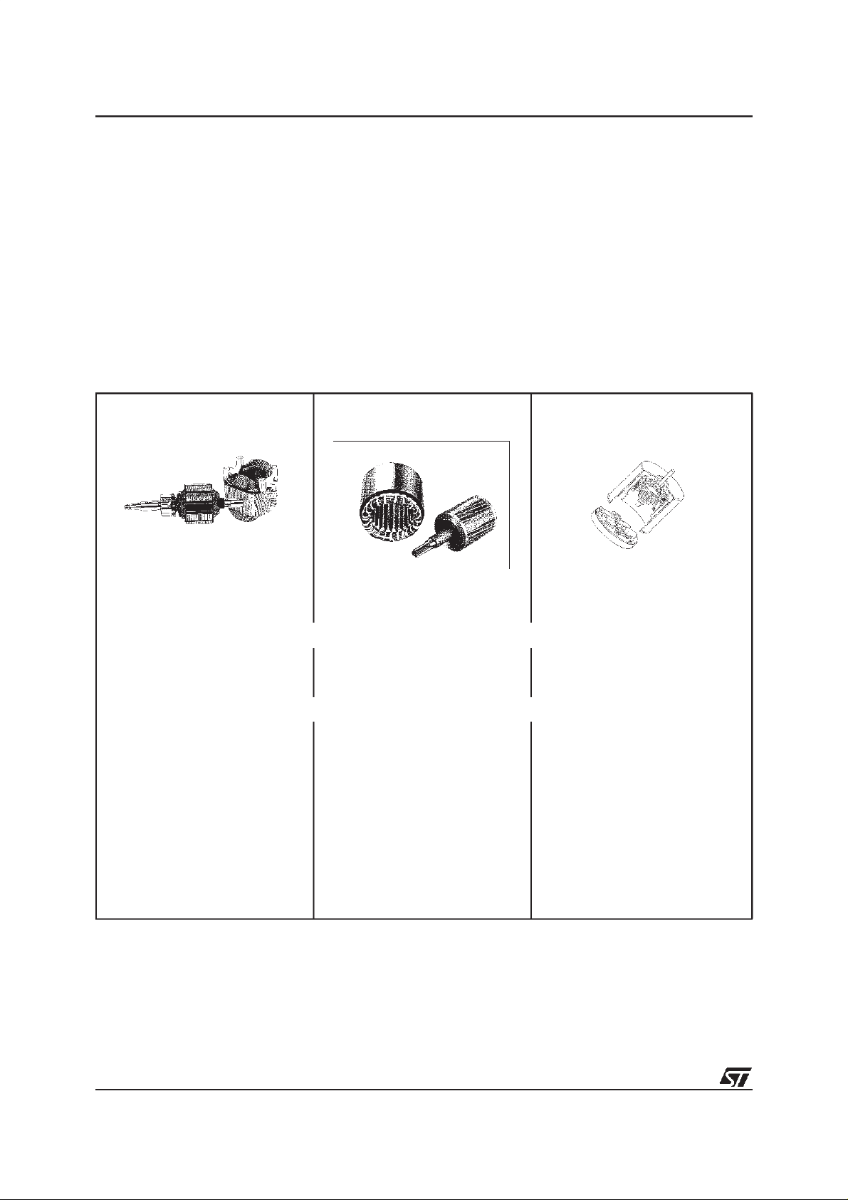
Figure 1. Features and typical applications of the three main types of electric
applicance motors
BRUSHLESS ELECTRONIC
WITH BRUSHES
BRUSHLESS
COMMUTATION
UNIVERSAL
– AC or DC supplied
– High torque at starting
– Washing machine (EU)
– Hand tools
– AC supplied
– Robust
– Washing machine (WW)
– Heating-Ventilation-Air
conditioning
INDUCTION
FEATURES
APPLICATIONS FIELDS
AUTOCOMMUTATED
Perm. Magnet or Var. Reluctance
– Electronic replaces brushes
– High torque at starting
– Washing machine
– H.V.A.C.
– Pump / Fan
– Immersed pump / Com-
pressor / Fan
– Food processor
– Vacuum cleaner
– Dish washer / Tumble drier
– Freezer / Refrigerator
– Food processor
– Vacuum cleaner
– Freezer / Refrigerator
– Universal (Brush) Motors are used in applications where high torque and/or variable speed
are required (e.g. drills, food-processors, hand-tools, vacuum cleaners, etc.). They can be
powered either by an AC or DC supply, and are currently the most popular motors in appliances. Dueto their poor efficiency and relatively limited life, universal motors are tending to
4/18
1

AN885 - THE RIGHT MOTOR FOR THE JOB
be replaced by newertypes when the cost of the necessary electronic controlsystems drops
to sufficiently low levels.
– Induction (Brushless) Motors are mainlyused in applications requiring silent operation, long
life and high safety levels (i.e. pumps, compressors, refrigerators, fans, etc.). These motors
are AC supplied and rotational speed does not vary easily, since it is synchronised with the
electrical mains frequency.
In the third family, electronic acts as an electronic commutator and takes the place of brushes.
– These Electronically Commutated Brushless Motors include Permanent Magnet Syn-
chronous Motors and Switched Reluctance Motors. Both types are controlled by electronically switching the current in the windings. Electronically Commutated Brushless Motors
combine the high torque and variable speed performance of the universal motor withtheabsence of brushes and the intrinsic ruggedness of the induction motor.
5/18
1
AN885 - UNIVERSAL MOTOR CONTROL
3 UNIVERSAL MOTOR CONTROL
3.1 PHASE ANGLE CONTROL MODE
Universal motor speed may be simply and economically varied by phase angle control using
a TRIAC: this is therefore a very popular solution [1]. The motor current is directly drawn from
the mains and, because of its large peak to peak value, power losses in the iron are high.
When the TRIAC conduction angle is less than full wave, the current drawn from the mains
contains low frequency harmonic components with high amplitudes which can easily exceed
the authorised IEC levels.
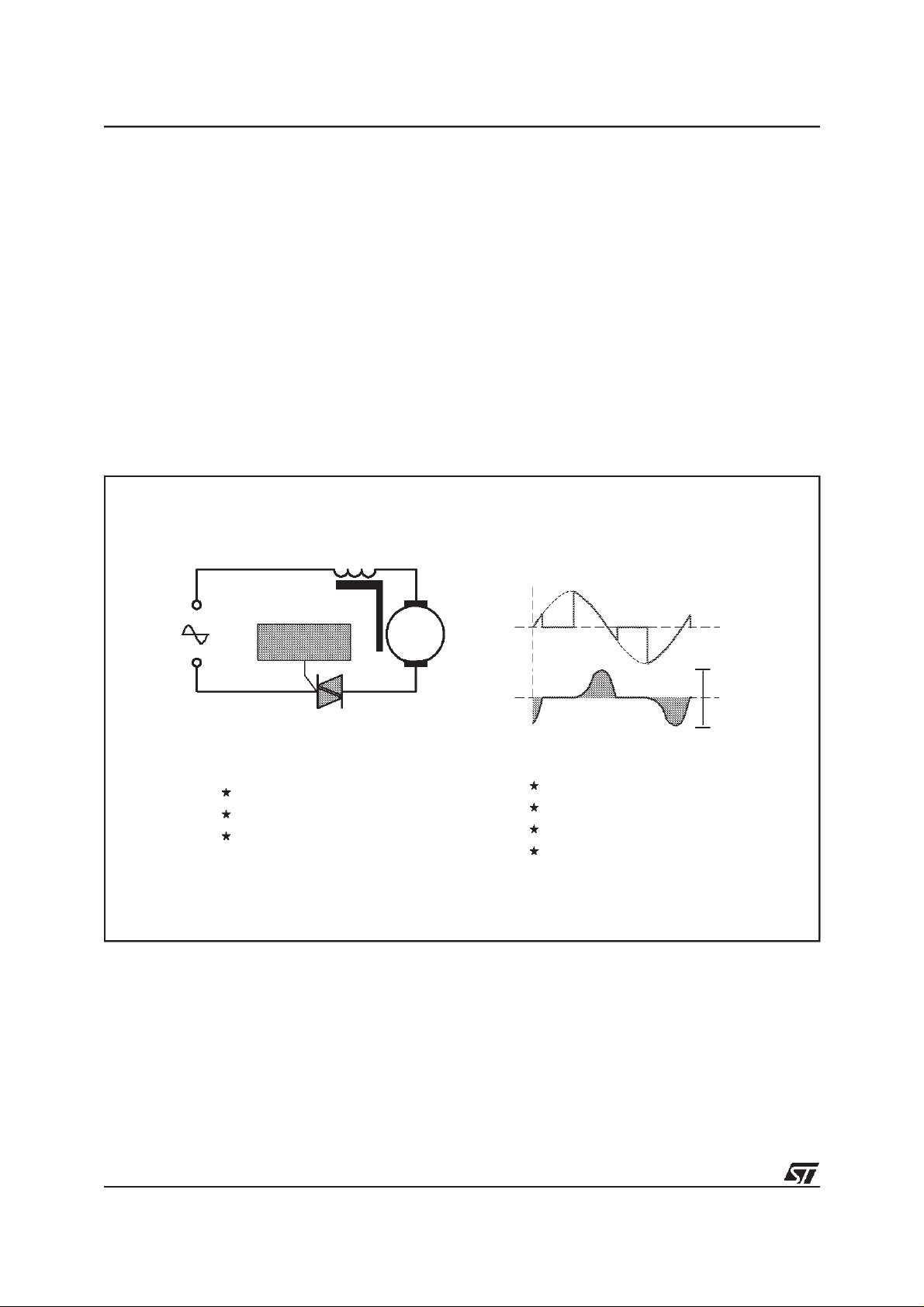
Figure 2. Universal brush motor driven by phase-angle triggered TRIAC switched AC
supply.
ST6210 MCU
strength
Directly on the mains
Cheap solution
Variable speed
TRIAC
M
Umot
Imot
weakness
High current ripple
Brushes Noise
Sparkes, RFI pertubations
Low life time (3000hrs)
t
∆
Ι
t
6/18
1

AN885 - UNIVERSAL MOTOR CONTROL
In the example of a washing machine motor controller (Figure 3.), the gate of the TRIAC is directly controlled by a low-cost ST6210 microcontroller. Each high current I/O pin on ST62
Family devices can drive 20 mA, thus one or more pins may be paralleled, depending on the
TRIAC’s gate drive requirements.
The ST62 Familymicrocontroller, thanks to its wide voltage supply range andbuilt-in noise immunity, can be directly supplied from the 220V mains using only a few low-cost external components, as illustrated in F igure 3. The ST6210 manages the various washing cycles, the
man-machine interfaces and motor speed control. Motor speed regulation can make use of a
tacho-generator, or can be sensorless [4].
The ST62 controlled solution is extremely economical, while providing maximum flexibility:
changes are simply, rapidly and economically implemented by modifying the ST62 control
program.
Figure 3. Speed regulation using ST6210 MCU driven TRIAC in a washing machine
application
LINE
TRIAC
230V
LOAD
NEUTRAL
FUSE
BTA 16-600CW
M
820-1/2W
47
5V6
0V
220nF/400V
10K
220nF
1N4148
+5V
0V0V
100ÿF
6V
INVER SION
0V
10K
+5V
0V
1M
+5V
1
VDD RESET
19
PA0
18
PA1
17
PA2
16
PA3
13
PB2
12
PB3
PB4
11
PB5
10
OSCIN OSCOUT
34
22p
PB0
S
T
PB1
6
PB6
2
PB7
1
NMI
TEST
0
VSS
PIEZO
22p
8MHz
0V
+5V
TEMPER ATUR E
15
WASH
0V
14
9
8
5
6
20
RAMP
LIMIT
0V0V
0V
+5V
+5V
0V0V
SPIN
RAMP
DURATION
7/18
1

AN885 - UNIVERSAL MOTOR CONTROL
3.2 CHOPPER CONTROL MODE
The universal motorcan be supplied by a rectified AC voltage, switched at a high frequency by
a power MOS transistor [3] [6]. Speed control is achieved by adjusting the chopper duty cycle
[9]. Because of the rectified voltage, the current ripple is low, and iron losses are therefore low
as well. (Figure 4.)
Figure 4. Chopper controlled Universal motor. mode
Umot
USER
Imot
weakness
20 kHz switching
Need RFI filtering
t
∆
Ι
t
230 V
TURBOSWITCH
Power
MOS
strength
Low current ripple
Reduced acoustic noise
M
TD300
SUPPLY
15 V
BUFFER
PEAK CURRENT
DETECTOR
5V
0V
Vdd
Ud
PWM
ST6265
Vss
MCU
INTERFACE
Ic
Better efficiency
The m ains current waveform is sinusoidal and thus does not generate low frequency harmonics.
Chopper control mode is an efficient means of complying with the IEC 1000-2-3 harmonics
standard. The pulsed current at the chopper frequencymust be filtered to remove components
at the switching frequency and above, but the filtering inductance need only be small, and
therefore low-cost, since the chopper frequency can be high (5 - 20kHz).
The chopper circuit comprises a power MOS transistor and a fast Turboswitch
TM
freewheeling
diode. The pulse width modulated (PWM) drive signal is generated by the ST62 microcontroller, via the STMicroelectronics TD300 MOS driver IC, which level shifts the 5V microcontroller output to the 15V level needed to drive the gate of the power MOS device. The MOS
driver IC also affords protection against short-circuits and over current. The ST62 microcontroller monitors the mains voltage and manages the user interfaces (signals and control).
8/18
1

AN885 - UNIVERSAL MOTOR CONTROL
3.3 HARMONICS AND POWER DRAWN FROM THE MAINS
The low frequency harmonics content generated on the mains strongly depends on the kind of
motor control used (phase angle or chopper).
For example, a vacuum cleaner operating in phase angle mode at reduced speed (i.e. conduction phase angle at around 90°), produces a very high level of even harmonics (Figure 5.).
The harmonics do not represent realoractive power, but nevertheless they lead to substantial
copper and iron losses. Consequently,the power supplied to the vacuum cleanerfor the same
mechanical output power is twice as high using phase angle control as it is when the chopping
control method is used.
Briefly, the chopper methodminimisesharmonicson the mains and increases motor efficiency
by a factor of two with respect to the phase angle control mode, as illustrated in Figure 5.
Motor size can thus be reduced and brush lifetime is much greater. In addition, in most applications no low frequency filtering or power factor correction is necessary to comply with the
IEC1000-2-3 standard. However, the high frequency harmonics generated by the chopper circuit (over 10kHz) must be blocked from the mains by means of a high frequency filter.
Figure 5. Current waveform and harmonics in phase angle control mode and chopper
control mode
5 A/[]
2ms
5 A/[]
2ms
Amps
5
4
3
2
1
0
12345
Amps
5
4
3
2
1
0
12345
= Standard limit
1000 W
Harmonics #
= Standard limit
600 W
Harmonics #
Example of a vacuum cleaner at reduced speed = 15 000 rpm
PHASE CONTROL
M
CHOPPER CONTROL
M
The mechanical load
of Motor remains
unchanged
9/18
1

AN885 - INDUCTION MOTOR CONTROL
4 INDUCTION MOTOR CONTROL
4.1 INDUCTION MOTOR SUPPLIED BY MONOPHASE AC
An induction m otor (also known as an asynchronous m otor) is directly supplied from the
monophase mains and can be controlled simply in “ON/OFF” mode using a TRIAC driven directly by a low-cost ST62 Familymicrocontroller (Figure 6.).
The reverse direction of rotation is obtained by using a second TRIAC controlled by the same
microcontroller.
Despite their low cost, these solutions give a great flexibility for design and operation, thanks
to the use of a microcontroller, allowing such functions as monitoring of motor torque and
mains voltage. Motor losses can be optimized by controlling undervoltage or Figure 3. Speed
regulation using ST6210 MCU driven TRIAC in a washing machine application overvoltage
according to working conditions and load (rotation speed, acceleration or deceleration, torque
demand).
Using this basic control, the motor speed cannot be easily adjusted, as it is fixed by the 50 or
60Hz mains frequency.
Figure 6. Induction Motor controlled in ON-OFF mode using TRIAC.
direct rotating
TRIAC
ST62xx
MCU
strength
Directly on the mains
Very silent
weakness
direct / reverse rotating
TRIAC
Fixed speed by mains frequency
Low starting torque
High lifetime (30 000 hrs)
ST62xx
MCU
10/18
1

AN885 - INDUCTION MOTOR CONTROL
4.2 VARIABLE SPEED CONTROL FOR MONOPHASE INDUCTION MOTORS
Variable speed is obtained by supplying the induction motor with a variable frequency AC
supply. An economical way of achieving this, is to use a four switch converter generating two
“8-step” square wave voltages phase shifted by 90° (Figure 7.). The start-up capacitor which
is normally used, is no longer necessary and the frequency (motor speed) can be adjusted
over a wide range. During start-up or speed-up/ speed-down sequences, the voltage can be
adapted to the frequency bythe ST62 Familymicrocontroller, providing the motor with a much
higher starting torque than is generally reached with the common “split capacitor” scheme illustrated in Figure 6.
Control of the low side transistors, which are referenced to ground, is via a dual low-side driver
STMicroelectronics IC. Two high side drivers drive the floating high-side transistors.
A low cost ST62 microcontroller generates the PWM signal, using the on-chip auto-reload
timer; this signal is used to adjust the motor voltage. It also produces the necessary information for sequential motor phase commutation.
Figure 7. Economical solution for variable speed control with a monophase Induction
Motor
L6380
S
PWM
T
T1
6
T2
2
T3
6
T4
5
L6380
TD 300
T3
13
2
T4
4
+
Motor
-
Variable speed
Standard MCU
Common induction motor technology
11/18
1

AN885 - ELECTRONIC MOTORS
5 ELECTRONIC MOTORS
Electronic motors have no brushes and are electronically commutated (electronics replacing
brushes). They offer the advantages of both variable speed and high starting torque of the universal motor, together with the absence of brushes, silence and long lifetime of the induction
motor. Nevertheless, electronically commutated motors require sophisticated electronics to
ensure commutation in the windings; they also require a rotor position detector.
Two basic types exist (Figure 8.):
Figure 8. Two types of electronically controlled motors which will be increasingly
adopted in home appliance applications
ELECTRONIC MOTOR SPECIFICS:
high life time 30 000 h
need rotor position detection
high torque at low speed
SN
S
N
Permanent Magnet brushless DC
silent
mature technology
N
S
S
N
Switched Reluctance
high speed (50 000 rpm)
emerging technology
compact
Synchronous motors with permanent magnet (PMDC).
This technology is already used in
the appliance field for fans and air-conditioners, mainly in the USA. Several manufacturers are
planning to use this motor type for other appliance applications.
Switc hed reluctan ce m oto r s (SRM ).
Switc he d re lu ctance technol ogy is cu rrent ly reemerging in appliance applications thanks to the rapidly falling cost of electronic control solutions. Many appliance manufacturers and research organisations are presently evaluating
feasibility, characteristics and total system cost in order to define acceptable solutions.
12/18
1

AN885 - ELECTRONIC MOTORS
5.1 PERMANENT MAGNET SYNCHRONOUS MOTOR (PMDC)
An autocommutated permanent magnet synchronous motor is driven by a common three
phase bridge, which sequentially supplies the current in the three phase motor windings in
both polarities (Figure 9.).
The ST62 Family microcontroller receives rotor position information and directly controls the
transistors, thus sequentially commutating the windings. The microcontroller also generates
the PWM signal, controlling the voltage across the motor.
Three standard high side driver STMicroelectronics ICs (L6380) shift the ground-referred control signals to the high side floating transistors. These ICs sustain >500V and can be used in
applications on 230V m ains. Another standard STMicroelectronics IC (TD300), a triple low
side driver, combines the phase commutation with the PWM signal for each of the three low
side transistors. It also monitors the current and acts for current limitation.
Figure 9. Common triphase bridge topology with driver ICs and ST microcontroller
controlling brushless PMDC motor in “6-step mode” with rotor position
sensors.
L6380
S
T1
T3
T
T5
6
2
PWM
x
T2
x
T4
T6
L6380
L6380
EN
TD 300
T3
T5
T2
T4
135
246
t
Motor
13/18
1

AN885 - ELECTRONIC MOTORS
5.2 SWITCHED RELUCTANCE MOTOR (SRM)
There are various power stage topologies to drive Switched Reluctance Motors. The most
common uses an asymmetrical bridge structure for each phase winding (Figure 10.).
This scheme recovers the corresponding energy in the power supply; it also authorises the
overlappi n g of conduction p hase se quen ces (simultaneo us conduction of two adjace nt
phases) giving maximum torque and speed [8]. This topology is versatile and robust, as there
is no risk of short circuits in the bridge-leg, because each motor winding is in series with the
two leg transistors.
Usually, global control includes two control loops: the autocommutation loop, including the
same number of position sensors as the number of phase windings, and the speed regulation
loop adjusting current in the phase by controlling the PWM duty cycle.
Figure 10. Common topology for a triple asymmetrical bridge driving a Switched
Reluctance Motor (SRM) using three rotor position sensors.
POSITION
SENSORS
SWITCHING
LOGIC
SPEED
REGULATION
CURRENT DEMAND
LIMITATION
&
CURRENT
CONTROL
+
-
14/18
1

AN885 - ELECTRONIC MOTORS
5.3 SIMPLIFIED TOPOLOGY FOR SWITCHED RELUCTANCE MOTORS
In home appliance applications, cost reduction is the major challenge. The objective is to reduce total system cost, and consequently the number of electronic components. ST62 Family
MCUs make a valuable contribution in this direction, since their wide operating supply range,
their built-in ruggedness, their legendary noise immunity and the wide range of available onchip peripherals drastically reduce external component count and cost
One solution uses a single sensor. The missing sensor signals are reconstructed by the ST62
Family microcontroller, saving two sensors. The microcontroller also measures speed, executes the control algorithm, and adjusts its internal PWM duty cycle to ensure the required
motor speed. [8]
The simplified topology in Figure 11. saves two power transistors and two fast diodes. Only
one hi gh side transistor remains, adjusting (PWM) and distributing current in each phase
winding when the low side transistors are successively switched.
An ST62 Family microcontroller drives the high side transistor via the L6380 high side driver
IC. The three low side transistors are driven via the triple low side driver IC (TD300), which
also ensures short circuit and over current protection.
The power stage includes four power MOS transistors and four fast diodes. Onlythe high side
transistor with its associated freewheeling fast diodes are switched at high frequency, and
have to be sized to carry the current of the three windings.
Each of the three low side transistors can be smaller, since they only have to switch the cur-
rent of one winding at low frequency.
15/18
1

AN885 - ELECTRONIC MOTORS
Figure 11. Simplified low cost ST62 MCU solution driving three phase SRM using a
single rotor position sensor.
PWM
L6380
220uF/385V
TD 300
220V
220uF/25V
4.7V
5.1V
5.1V
22uF
ST6260
10K
2.2K
15K
POSITION
SENSOR
16/18
1

AN885 - ELECTRONIC MOTORS
5.4 ST6260 OFFERS THE SIMPLEST SRM DRIVER
As an example, we can imagine an ideal SRM drive in terms of cost as shown in Figure 12.
This is a single phase motor, running only at high speed, controlled by an ST62 microcontroller. The component count is low and the circuitcan be assembled on an single board within
the motor casing: this is an excellent example of ultra low total system cost.
Figure 12. Simplest motor drive for a single phase switched reluctance motor supplied
in current mode, controlled by an ST6260 MCU
SET CURRENT
230vV
5.5 ST62: LOWEST TOTAL SYSTEM COST
DERIVATOR
PWM
ST6260
L6382
ΦΑ
Delay angle
adjustment
POSITION SENSOR
&
SPEED MEASUREMENT
The use of MCU driven electronic control systems indomestic appliance motor control will become moreand more commonthanks to the availability of flexible, reliableand low-cost MCUs
such as ST M icro electronics ST 62 Fa mil y, w here the i ntegration o f powerful on-chip resources, wide operating supply voltages, built-in ruggedness and legendary noise immunity
allow the designer to achieve very low total system costs.
In this way, large volume markets will be created, leading to further economies of scale and
greater market penetration.
17/18

AN885 - STMICROELECTRONICS APPLICATION NOTES
6 STMICROELECTRONICS APPLICATION NOTES
[1] Microcontroller and Triacs on the 110/240V Ph.RABIER/L.PERIER A.N 392
P.GUILLEMIN
[2] Digital P.F.C with Non-Sinewave Current
[3] “Controlling a brush DC motor with an ST6265 J.NICOLAI/T.CASTAGNET A.N.414
[4] “Sensorless Motor Drive with ST62MCU + Triac T.CASTAGNET A.N.416
[5] “An approach to Motor Control with Fuzzy Logic P.GUILLEMIN A.N.419
/J.M CHARRETON
/B.MAURICE
A.N.412
[6] “Improved Universal Motor Drive
[7] “Versatile and Costeffectiveinduction motor drive with
digital three phase generation
[8] “Simplified electronics bring the Switched-Reluctance
motor to the mass market
[9] “PWM techniques for acoustic noise reduction in power application
J.M BOURGEOIS
/J.M.CHARRETON/P.RAULT
B.MAURICE
/J.M BOURGEOIS/B.SABY
AN422
A.N.424
J.NICOLAI EPE ’95
J.M BOURGEOIS AN519
[10] “Inverter Design for mass production J.M BOURGEOIS PCIM’95
Information furnished is believed to be accurate and reliable. However, STMicroelectronics assumes no responsibility for the consequences
of use of such information norfor any infringementof patents or other rights of third parties which may resultfrom its use. No license isgranted
by implication or otherwise under any patent or patent rights of STMicroelectronics. Specifications mentioned in this publication are subject
to change without notice. This publication supersedes and replaces all informationpreviously supplied. STMicroelectronics products are not
authorized for use as criticalcomponents in life support devices or systems without the express writtenapproval of STMicroelectronics.
The ST logo is a registered trademark of STMicroelectronics
2
Purchase of I
Australia - Brazil - Canada - China - France - Germany - Italy - Japan - Korea - Malaysia - Malta - Mexico - Morocco - The Netherlands -
18/18
C Components by STMicroelectronicsconveys a license under the Philips I2C Patent. Rights touse these components in an
2
C system is granted provided that the system conforms to the I2C Standard Specification as defined by Philips.
I
Singapore - Spain - Sweden - Switzerland - Taiwan - Thailand - United Kingdom - U.S.A.
1998 STMicroelectronics - All Rights Reserved.
STMicroelectronics Group of Companies
 Loading...