

ST LM236, LM336 User Manual
Features
● Low temperature coefficient
● Wide operating current of 400µA to 10mA
● 0.2Ω dynamic impedance
● Guaranteed temperature stability
● Fast turn-on
Description
The LM236 and LM336 are precision 2.5V
regulator diodes. These voltage reference
monolithic ICs operate like 2.5V Zener diodes
with a low temperature coefficient and a dynamic
impedance of 0.2Ω. A third pin enables adjusting
the reference voltage and the temperature
coefficient.
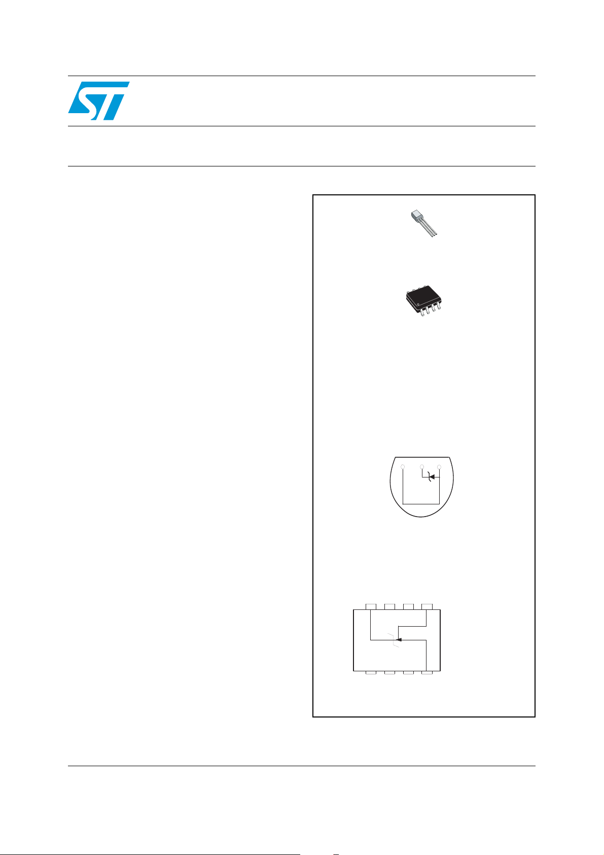
LM236-LM336
2.5V voltage references
TO92
(Plastic package)
SO8
(Plastic micropackage)
Pin connections
TO92
(Bottom view)
v+
v-
ADJ
SO8
(Top view )
V+ NC
8765
NC
ADJ
1- NC
2- NC
3- NC
4- V5- ADJ
6- NC
1234
NC
NC
NC
7- NC
V+
8- V+
May 2007 Rev 3 1/15
www.st.com
15
Schematic diagram LM236-LM336
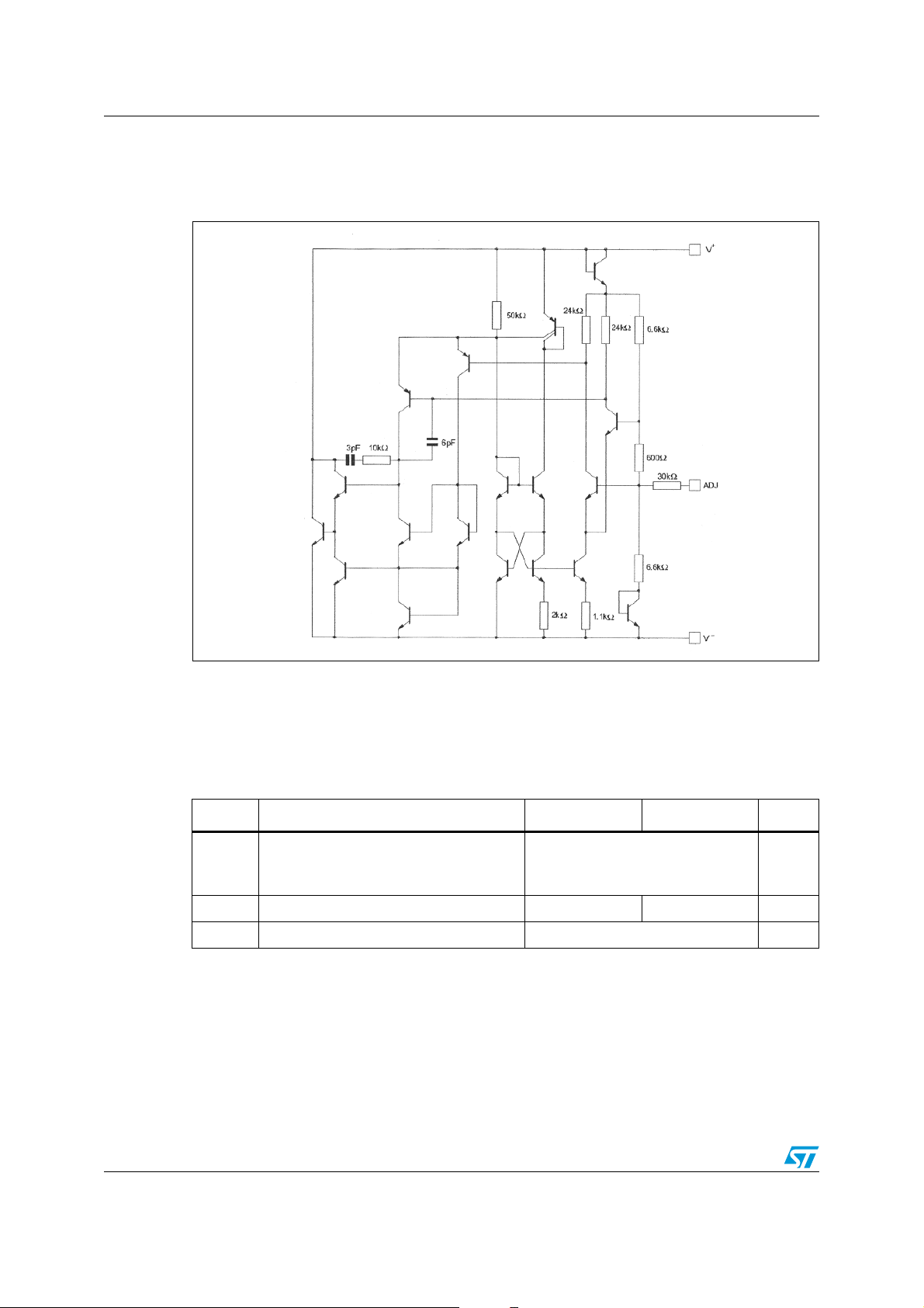
1 Schematic diagram
Figure 1. Schematic diagram
2 Absolute maximum ratings
Table 1. Absolute maximum ratings (AMR)
Symbol Parameter LM236 LM336,B Unit
Current
I
R
I
F
T
oper
T
stg
2/15
Reverse
Forward
Operating free-air temperature range -25 to +85 0 to +70 °C
Storage temperature range -65 to +150 °C
15
10
mA
LM236-LM336 Electrical characteristics
3 Electrical characteristics
Table 2. Electrical characteristics
LM236 LM336,B
Symbol Parameter
Min. Typ. Max. Min. Typ. Max.
Reference breakdown voltage
= +25°C, IR = 1mA
T
V
amb
R
LM236, LM336
LM336B
2.44 2.49 2.54 2.39
2.44
Reverse breakdown voltage change with current
ΔV
400µA ≤ IR ≤ 10mA
R
T
amb
T
≤ T
min
= +25°C
amb
≤ T
max
2.6
3
6
10
Reverse dynamic impedance (IR = 1mA)
Z
D
K
VT
K
VH
T
T
amb
min
= +25°C
≤ T
amb
≤ T
max
0.2
0.4
0.6
1
Temperature sta b ili ty (VR = 2.49V, IR = 1mA) 3.5 9 1.8 6 mV
Long term stability (T
= +25°C ±0.1°C, IR= 1mA) 20 20 ppm
amb
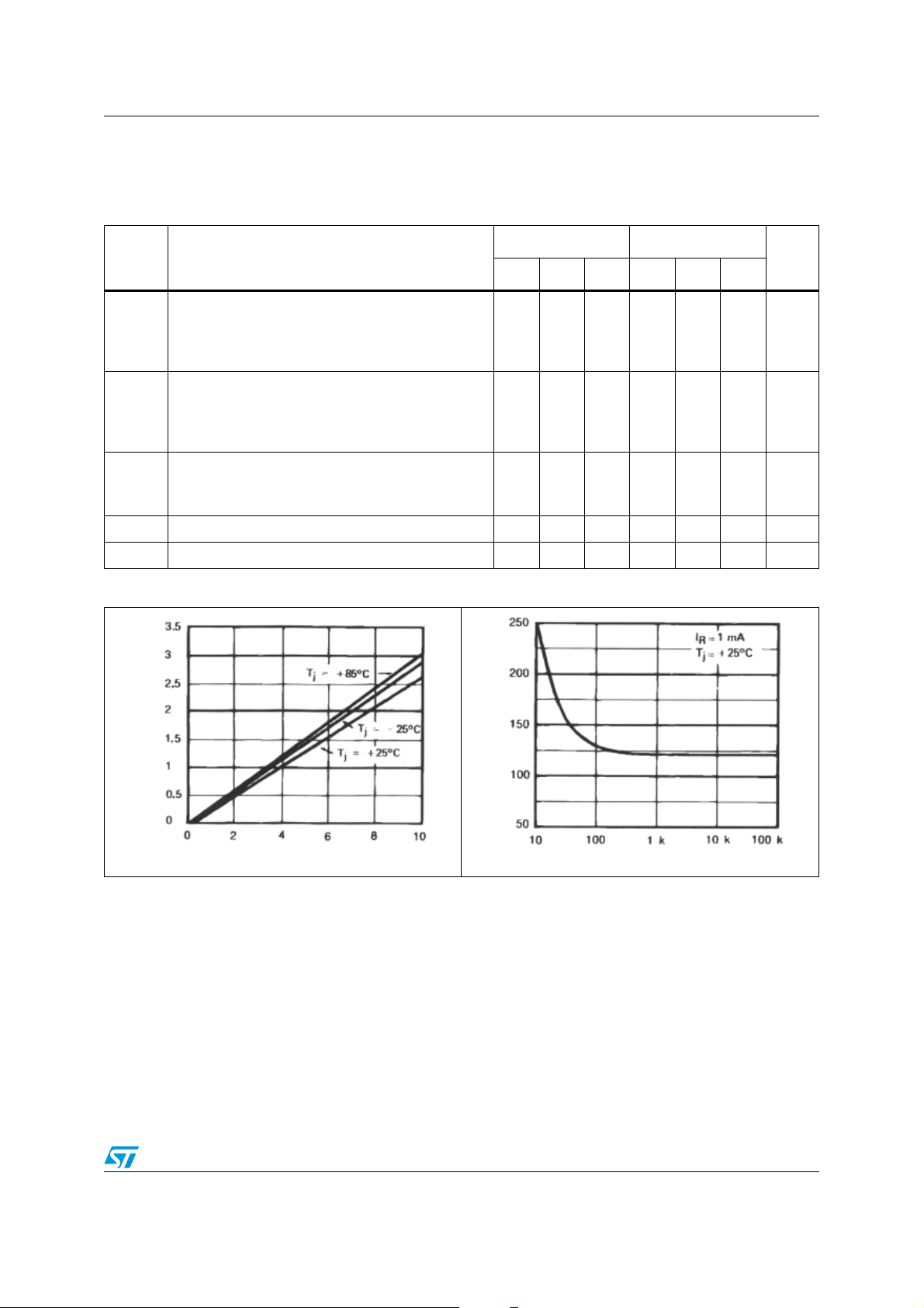
Figure 2. Reverse voltage change Figure 3. Zener noise voltage
Unit
2.49
2.59
2.49
2.54
2.631012mV
0.2
0.411.4
V
Ω
Reverse voltage change (mV)
Reverse current (mA)
Noise (nV/√Hz)
Frequency (Hz)
3/15
Electrical characteristics LM236-LM336
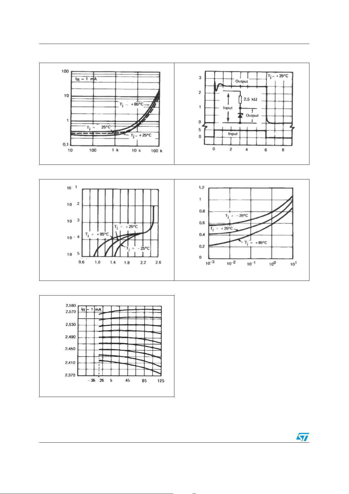
Figure 4. Dynamic impedance Figure 5. Response time
Voltage swing (V)
Dynamic impedance (Ohm)
Frequency (Hz)
Time (µs)
Figure 6. Reverse characteristics Figure 7. Forward characteristics
Reverse current (mA)
Reverse voltage (V)
Figure 8. Temperature drift
Reverse voltage (V)
Temperatur e (°C)
Forward voltage (V)
Forward current (mA)
4/15
LM236-LM336 Application information
4 Application information
The LM236, LM336 voltage references are easier to use than zener diodes. Their low
impedance and wide current range facilitate biasing in any circuits . Besides , the breakdo wn
voltage or the temperature coefficient can be adjusted so as to optimize the performance of
the circuit.
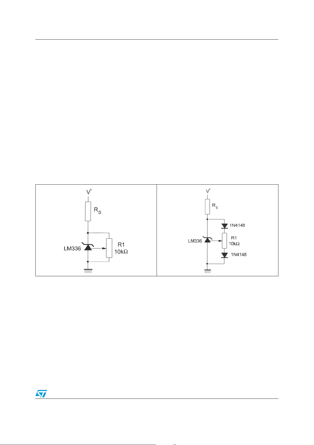
Figure 9 represents a LM336 with a 10kΩ potentiometer to adjust the reverse breakdown
voltage which can be a djusted without altering the temper atur e coeff icient of the circu it. The
adjustment range is generally sufficient to adjust the initial tolerance of the circuit and the
inaccuracy of the amplifier circuit.
To obtain a lower temperature coefficient two diodes can be connected in series as
indicated in Figure 10.
When the circuit is adjusted to 2.49V the temperature coefficient is minimized.
For a correct temperature coefficient, the diodes should be at the same ambient
temperature as the LM336. The value of R1 is not critical (2-20kΩ).
Figure 9. LM336 with pot for adjustment of
Figure 10. Temperature coefficient adjustment
breakdown volta ge
5/15
 Loading...