

Three terminal adjustable current sources
Features
■ Operates from 1V to 40V
■ 0.02%/V current regulation
■ Programmable from 1µA to 10mA
■ ±3% initial accuracy
Description
The LM134/LM234/LM334 are 3-terminal
adjustable current sources characterized by:
■ an operating current range of 10000: 1
■ an excellent current regulation
■ a wide dynamic voltage range of 1V t 10V
The current is determined by an external resistor
without requiring other external components.
Reverse voltages of up to 20V will only draw a
current of several microamperes. This enables the
circuit to operate as a rectifier and as a source of
current in a.c. applications.
LM134-LM234-LM334
Z
TO-92
(Plastic package)
D
SO-8
(Plastic micropackage)
Pin connections
TO-92
(Bottom view)
For the LM134/LM234/LM334, the voltage on the
control pin is 64mV at +25°C and is directly
ADJ
v+
21
v-
3
proportional to the absolute temperature (°K). T he
simplest external resistor connection generates a
current with approxima tely 0. 33%/°C te mper ature
dependence. Zero drift can be obtained by adding
an additional resistor and a diode to the e xternal
circuit.
SO-8
(Top view)
NC NC
8765
1234
ADJ
NC
May 2007 Rev 3 1/16
NC
V-
NC
V+
www.st.com
16
Schematic diagram LM134-LM234-LM334
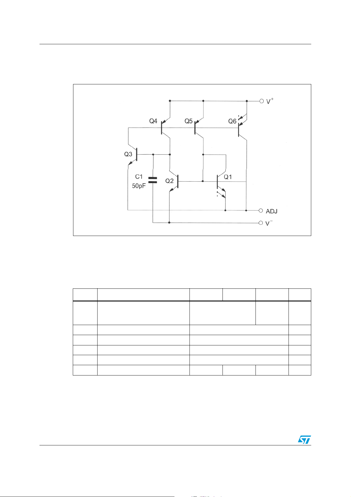
1 Schematic diagram
Figure 1. Schematic diagram
2 Absolute maximum ratings
Table 1. Absolute maximum ratings
Symbol Parameter LM134 LM234 LM334 Unit
Voltage V+ to V-
Forward
Reverse
-
V
P
T
T
ADJ pin to V- voltage 5 V
ADJ
I
Set current 10 mA
set
Power dissipation 400 mW
tot
Storage temperature range -65 to +150 °C
stg
Operating free-air temperature range -55 to +125 -25 to +100 0 to +70 °C
oper
40
20
30
20
V
2/16
LM134-LM234-LM334 Electrical characteristics
3 Electrical characteristics
Tj = +25°C with pulse testing so that junction temperature does not change during testing
(unless otherwise specified)
Table 2. Electrical characteristics
Set current error (V+ = +2.5V) -
10µA ≤ I
1mA ≤ I
2µA ≤ I
Ratio of set current to V
10µA ≤ I
1mA ≤ I
2µA ≤ I
Minimum operating voltage
2µA ≤ I
100µA ≤ I
1mA ≤ I
Average change in set current with input voltage
2µA ≤ I
+1.5V ≤ V
+5V ≤ V+ ≤ +40V
1mA ≤ I
+1.5V ≤ V+ ≤ +5V
+5V ≤ V
Temperature dependence of set current 25µA ≤ I
Effective shunt capacitance 15 15 pF
1. The set current is the current flowing into the V+ pin. It is determined by the following formula:
= 67.7mV/R
I
set
The set current error is expressed as a percent deviation from this amount.
is directly proportional to absolute temperature (°K). I
2. I
set
= Io (T/To)
I
set
where I
LM134 - LM234 LM334
Parameter
Min. Typ. Max. Min. Typ. Max.
(1)
≤ 1mA
set
≤ 5mA
set
≤ 10µA
set
current
-
14 18
14
14
0.8
0.9
1
0.02
set
set
set
set
≤ 1mA
set
≤ 1mA
set
≤ 5mA
≤ 10µA
≤ 100µA
≤ 1mA
set
≤ 5mA
+
≤ +5V
0.01
≤ 5mA
set
+
≤ +40V
(2)
≤ 1mA 0.96 T T 1.04 T 0.96 T T 1.04 T
set
(Tj = +25°C)
set
at any temperature can be calculated from
set
is I
measured at To (°K).
o
set
0.03
0.02
3
5
8
23 14 18
0.05
0.03
14
14
0.8
0.9
1
0.02
0.01
0.03
0.02
Unit
6
8
%
12
26
V
0.1
0.05 % / V
3/16
Electrical characteristics LM134-LM234-LM334
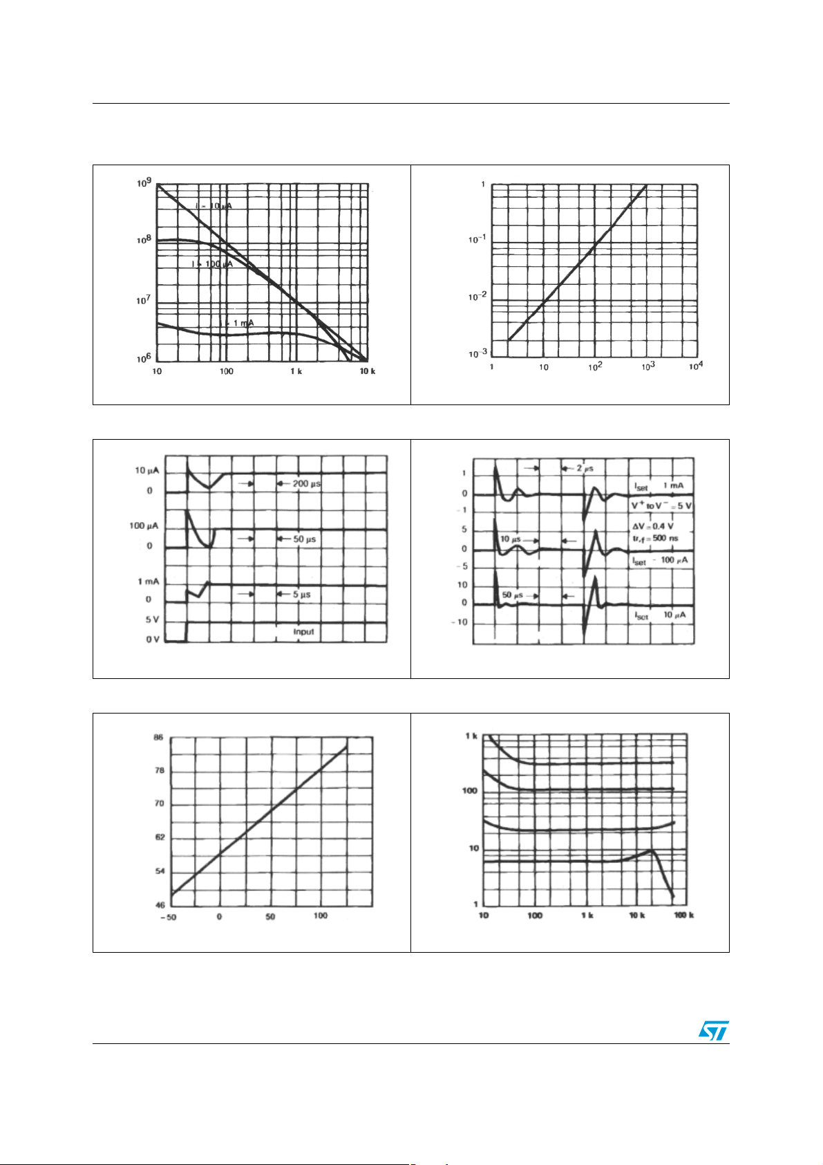
Figure 2. Output impedance Figure 3. Maximum slew rate for linear
operation
Impedance (Ohm)
Frequency (Hz)
Slew rate (V/µs)
I
set
(µA)
Figure 4. Startup Figure 5. Transient response
Time (scale changes at each current level) Time (scale changes at each current level)
Figure 6. Voltage across R
set
Figure 7. Current noise
Voltage (mV)
Current (pA/√Hz)
Temperature (°C)
4/16
Frequency (Hz)
LM134-LM234-LM334 Electrical characteristics
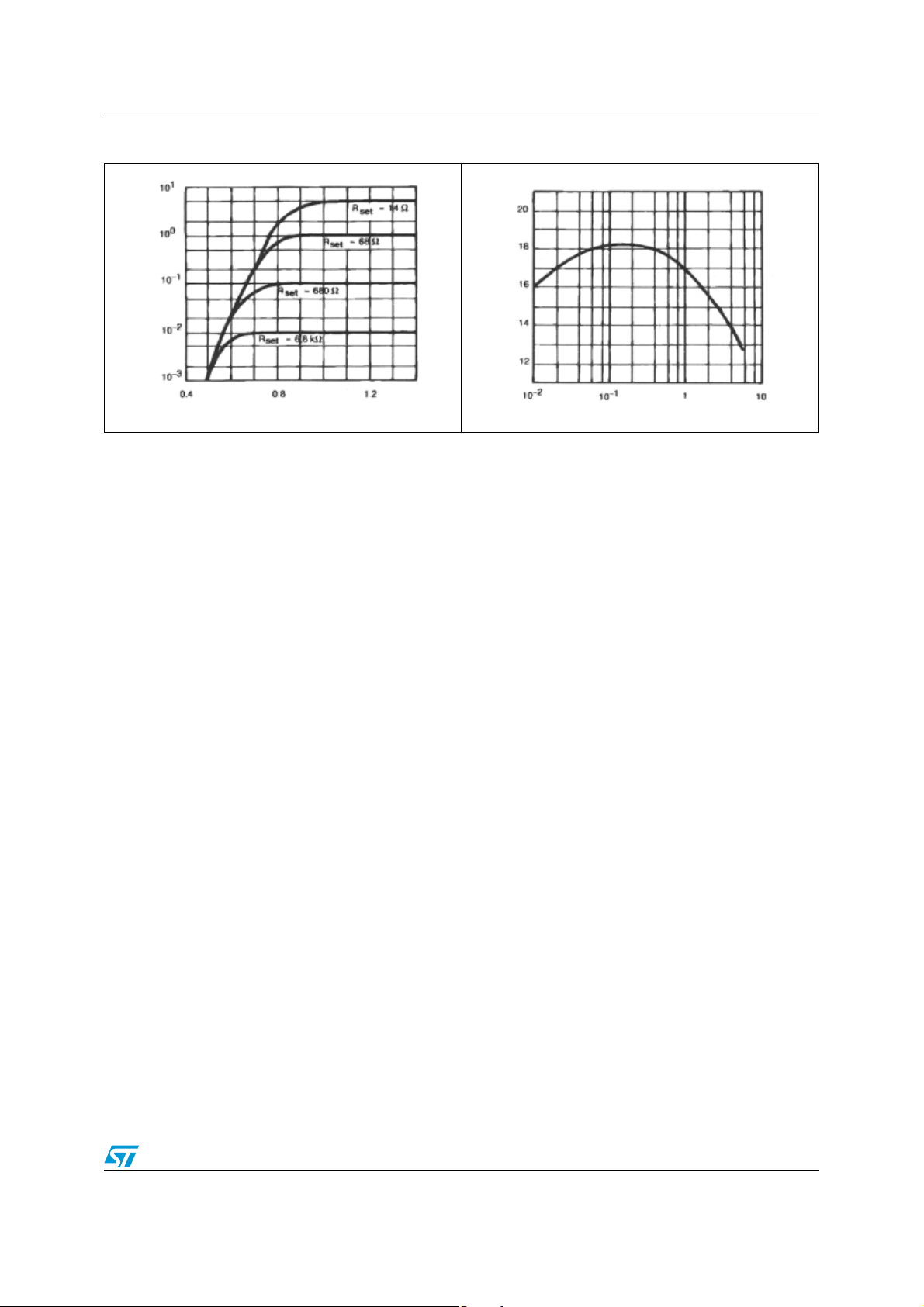
Figure 8. Turn-on voltage Figure 9. Ratio of I
(mA)
I
set
Ratio
V+ to V- voltage (V)
to V- current
set
I
(mA)
set
5/16
 Loading...