How it Works
Log In / Sign Up
Buy Points
How it Works
FAQ
Contact Us
Questions and Suggestions
Users
ST
Loading...
L
LM138
LM139
LM146
2
LM148
LM158
2
LM158 A
LM158W
LM193
LM193A
LM201A
LM211
LM217
LM217L
LM217M
LM219
2
LM223
LM224
4
LM224A
LM224W
2
LM234
LM235
LM236
2
LM238
LM239
LM246
2
LM248
LM258
2
LM258 A
LM258W
LM2901
LM2901H
LM2902W
LM2903
LM2903H
LM2903W
LM2904
2
LM2904A
LM2904W
LM2904WH
LM293
LM293A
LM301A
LM311
LM317
LM317L
LM317M
LM319
2
LM323
2
LM324
4
LM324A
LM324W
2
LM334
LM335
LM336
LM336B
LM337
LM338
LM339
LM346
2
LM348
LM350
LM358
2
LM358 A
LM358W
LM393
LM393A
LM4041AECT-1.2
LM4041AELT-1.2
LM4041AICT-1.2
LM4041AILT-1.2
LM4041BECT-1.2
LM4041BELT-1.2
LM4041BICT-1.2
LM4041BILT-1.2
LM4041CECT-1.2
LM4041CELT-1.2
LM4041CICT-1.2
LM4041CILT-1.2
LM4041DECT-1.2
LM4041DELT-1.2
LM4041DICT-1.2
LM4041DILT-1.2
LM723
LM833
LMV321
LMV321L
LMV324
LMV324L
LMV331
LMV339
LMV358
LMV358L
LMV393
LMV820
LMV820A
LMV821
LMV821A
LMV822
LMV822A
LMV823
Loading...
Loading...
Nothing found
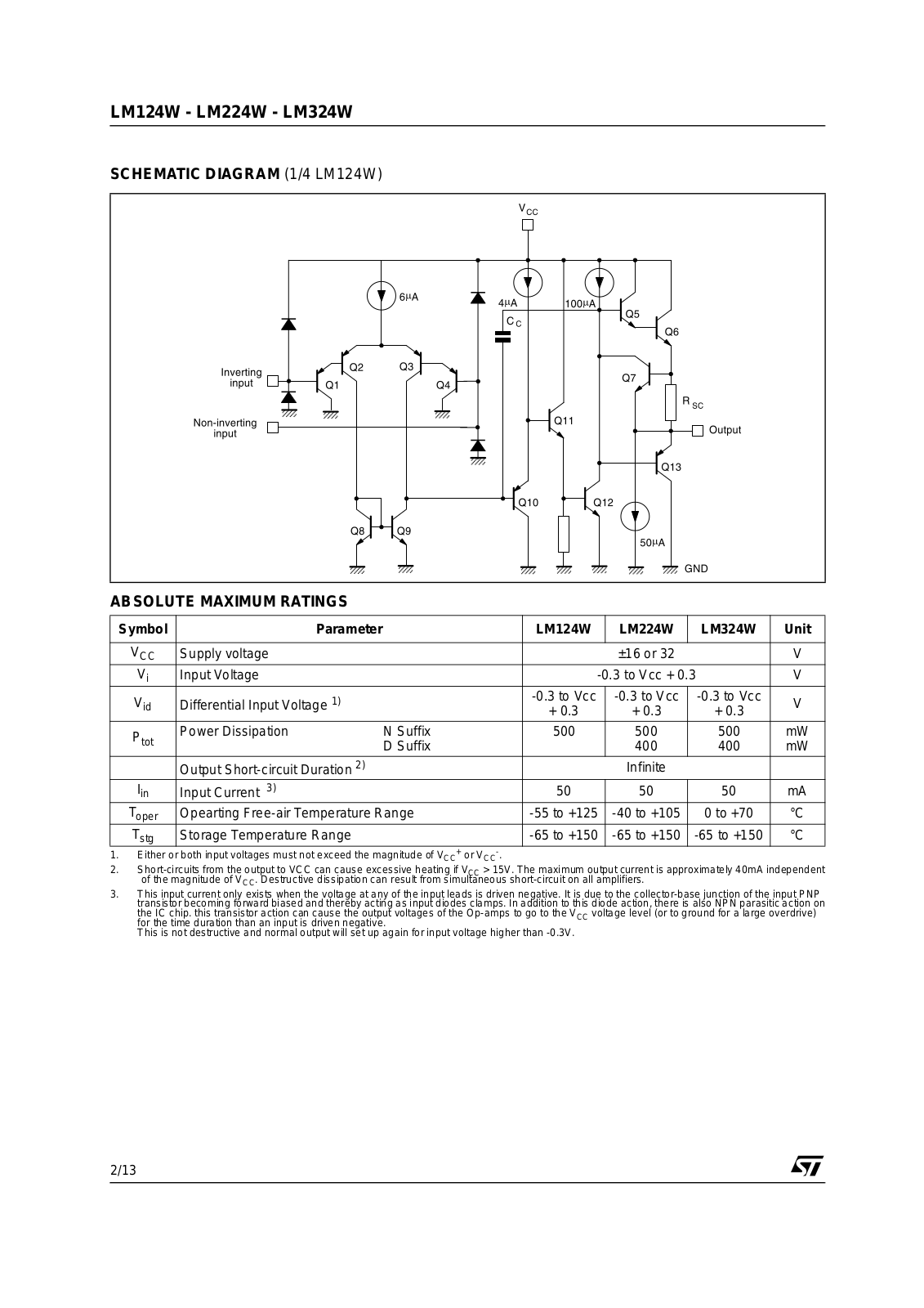
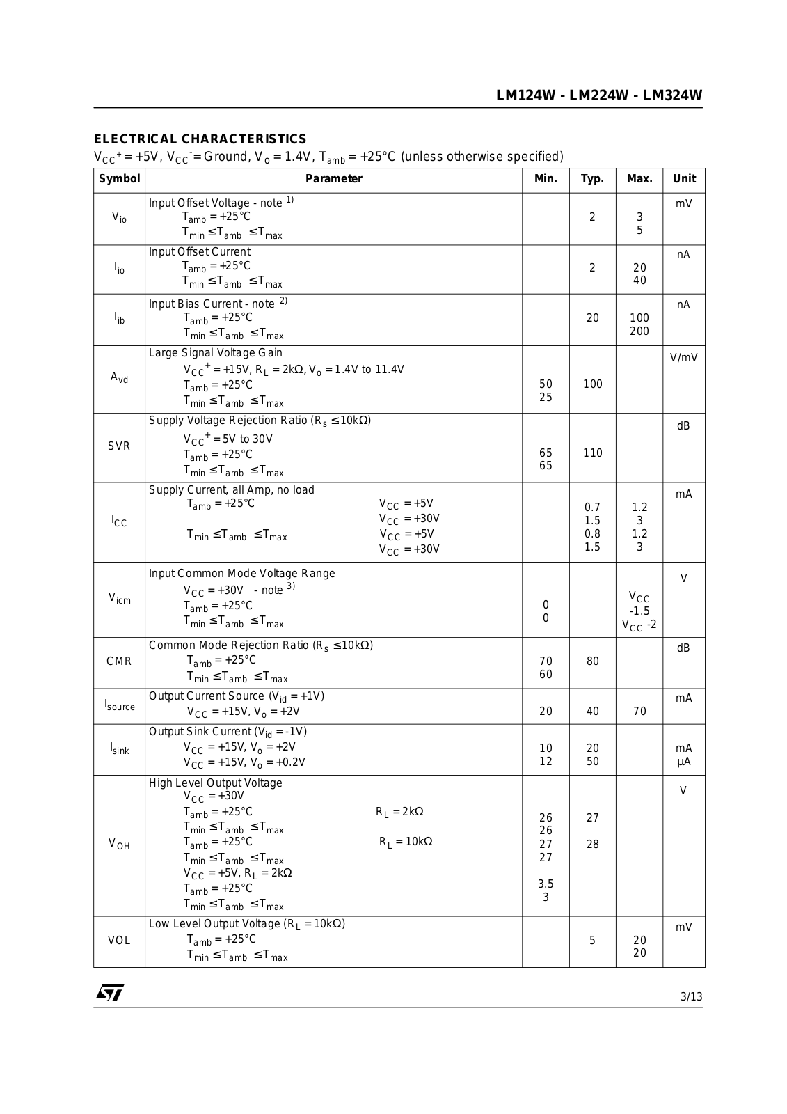
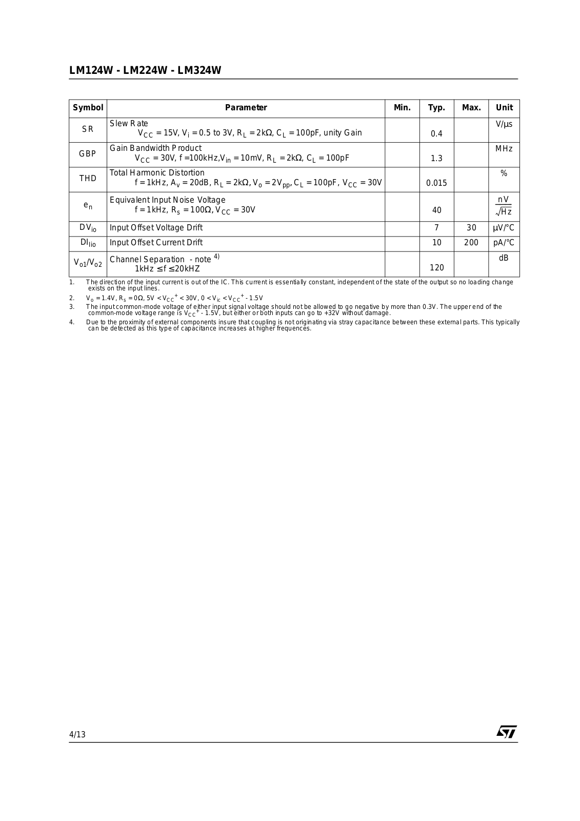
LM324W
Operation Manual
13 pgs
623.1 Kb
0
User Manual
16 pgs
797.77 Kb
0
Table of contents
Loading...
ST LM124W, LM224W, LM324W Operation Manual
...
ST Operation Manual
Download
Specifications and Main Features
Frequently Asked Questions
User Manual
Download
Loading...
+
9
hidden pages
Unhide
You need points to download manuals.
1 point = 1 manual.
You can buy points or you can get point for every manual you upload.
Buy points
Upload your manuals
 Loading...