

Features
■ Enable and sense inputs (EN, SI) protected
against negative transients down to -5 V
■ Reset threshold adjustable from 3.8 V to 4.7 V
■ Extremely low quiescent current, 65 µA (less
than 90 µA) in standby mode
■ Operating DC supply voltage range 5 V - 28 V
■ Operating transient supply voltage up to 40 V
■ High precision standby output voltage 5 V ± 1%
with 100 mA current capability
■ Output 2 voltage 5 V ± 2% with 400 mA current
capability (ADJ wired to V
■ Output 2 voltage adjustable by external voltage
divider
■ Output 2 disable function for standby mode
OUT2
)
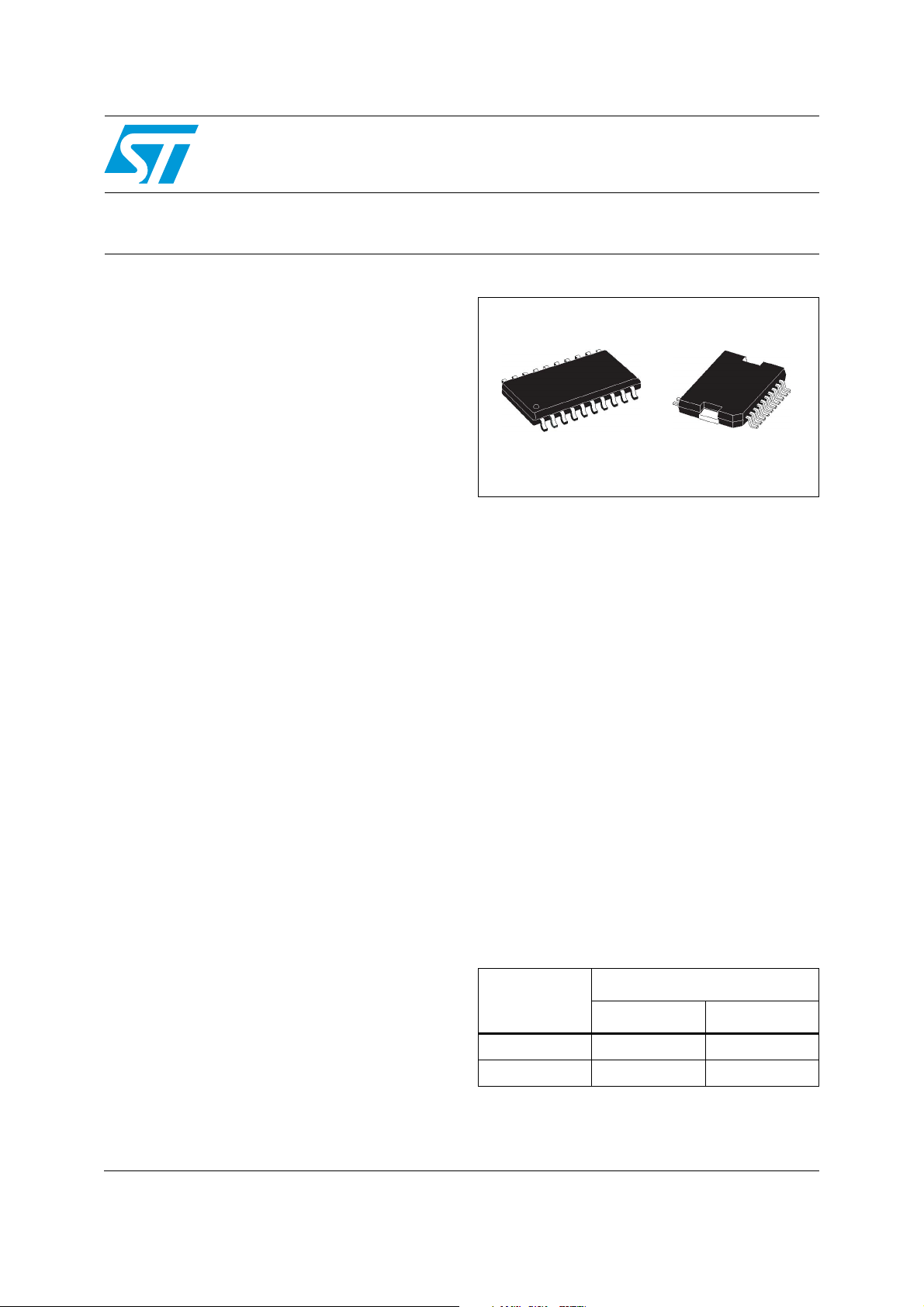
L4938ED
L4938EPD
Advanced voltage regulator
SO-20
Description
The L4938ED and L4938EPD are monolithic
integrated dual voltage regulators with two very
low dropout outputs and additional functions such
as power-on reset and input voltage sense. They
are designed for supplying microcomputer
controlled systems especially in automotive
applications.
PowerSO-20
Table 1. Device summary
Order codes
Package
Tube Tape and reel
SO-20 L4938ED L4938ED013TR
PowerSO-20 L4938EPD L4938EPD13TR
March 2010 Doc ID 17243 Rev 1 1/20
www.st.com
1

Contents L4938ED, L4938EPD
Contents
1 Block diagram and pin description . . . . . . . . . . . . . . . . . . . . . . . . . . . . . 5
2 Electrical specifications . . . . . . . . . . . . . . . . . . . . . . . . . . . . . . . . . . . . . . 7
2.1 Absolute maximum ratings . . . . . . . . . . . . . . . . . . . . . . . . . . . . . . . . . . . . . 7
2.2 Thermal data . . . . . . . . . . . . . . . . . . . . . . . . . . . . . . . . . . . . . . . . . . . . . . . 8
2.3 Electrical characteristics . . . . . . . . . . . . . . . . . . . . . . . . . . . . . . . . . . . . . . . 8
3 Application information . . . . . . . . . . . . . . . . . . . . . . . . . . . . . . . . . . . . . 11
3.1 Functional description . . . . . . . . . . . . . . . . . . . . . . . . . . . . . . . . . . . . . . . 11
3.2 Standby regulator . . . . . . . . . . . . . . . . . . . . . . . . . . . . . . . . . . . . . . . . . . 11
3.3 Output 2 voltage . . . . . . . . . . . . . . . . . . . . . . . . . . . . . . . . . . . . . . . . . . . 12
3.4 Reset circuit . . . . . . . . . . . . . . . . . . . . . . . . . . . . . . . . . . . . . . . . . . . . . . . 12
3.5 Sense comparator . . . . . . . . . . . . . . . . . . . . . . . . . . . . . . . . . . . . . . . . . . 13
3.6 Thermal protection . . . . . . . . . . . . . . . . . . . . . . . . . . . . . . . . . . . . . . . . . 13
3.7 Transient sensitivity . . . . . . . . . . . . . . . . . . . . . . . . . . . . . . . . . . . . . . . . . 13
3.8 Input protection . . . . . . . . . . . . . . . . . . . . . . . . . . . . . . . . . . . . . . . . . . . . 15
4 Package and packing information . . . . . . . . . . . . . . . . . . . . . . . . . . . . . 16
4.1 ECOPACK® packages . . . . . . . . . . . . . . . . . . . . . . . . . . . . . . . . . . . . . . . 16
4.2 SO-20 package information . . . . . . . . . . . . . . . . . . . . . . . . . . . . . . . . . . . 16
4.3 PowerSO-20 package information . . . . . . . . . . . . . . . . . . . . . . . . . . . . . . 17
5 Revision history . . . . . . . . . . . . . . . . . . . . . . . . . . . . . . . . . . . . . . . . . . . 19
2/20 Doc ID 17243 Rev 1

L4938ED, L4938EPD List of tables
List of tables
Table 1. Device summary . . . . . . . . . . . . . . . . . . . . . . . . . . . . . . . . . . . . . . . . . . . . . . . . . . . . . . . . . . 1
Table 2. Pin definitions and functions . . . . . . . . . . . . . . . . . . . . . . . . . . . . . . . . . . . . . . . . . . . . . . . . . 6
Table 3. Absolute maximum ratings . . . . . . . . . . . . . . . . . . . . . . . . . . . . . . . . . . . . . . . . . . . . . . . . . . 7
Table 4. Thermal data. . . . . . . . . . . . . . . . . . . . . . . . . . . . . . . . . . . . . . . . . . . . . . . . . . . . . . . . . . . . . 8
Table 5. OUT1 . . . . . . . . . . . . . . . . . . . . . . . . . . . . . . . . . . . . . . . . . . . . . . . . . . . . . . . . . . . . . . . . . . 8
Table 6. OUT2 . . . . . . . . . . . . . . . . . . . . . . . . . . . . . . . . . . . . . . . . . . . . . . . . . . . . . . . . . . . . . . . . . . 8
Table 7. OUT1, OUT2. . . . . . . . . . . . . . . . . . . . . . . . . . . . . . . . . . . . . . . . . . . . . . . . . . . . . . . . . . . . . 9
Table 8. Enable input . . . . . . . . . . . . . . . . . . . . . . . . . . . . . . . . . . . . . . . . . . . . . . . . . . . . . . . . . . . . . 9
Table 9. Reset circuit . . . . . . . . . . . . . . . . . . . . . . . . . . . . . . . . . . . . . . . . . . . . . . . . . . . . . . . . . . . . . 9
Table 10. Sense comparator . . . . . . . . . . . . . . . . . . . . . . . . . . . . . . . . . . . . . . . . . . . . . . . . . . . . . . . 10
Table 11. SO-20 mechanical data . . . . . . . . . . . . . . . . . . . . . . . . . . . . . . . . . . . . . . . . . . . . . . . . . . . 16
Table 12. PowerSO-20 mechanical data . . . . . . . . . . . . . . . . . . . . . . . . . . . . . . . . . . . . . . . . . . . . . . 17
Table 13. Document revision history . . . . . . . . . . . . . . . . . . . . . . . . . . . . . . . . . . . . . . . . . . . . . . . . . 19
Doc ID 17243 Rev 1 3/20

List of figures L4938ED, L4938EPD
List of figures
Figure 1. Block diagram . . . . . . . . . . . . . . . . . . . . . . . . . . . . . . . . . . . . . . . . . . . . . . . . . . . . . . . . . . . . 5
Figure 2. Configuration diagram (top view) . . . . . . . . . . . . . . . . . . . . . . . . . . . . . . . . . . . . . . . . . . . . . 5
Figure 3. Application diagram . . . . . . . . . . . . . . . . . . . . . . . . . . . . . . . . . . . . . . . . . . . . . . . . . . . . . . 11
Figure 4. OUT2 . . . . . . . . . . . . . . . . . . . . . . . . . . . . . . . . . . . . . . . . . . . . . . . . . . . . . . . . . . . . . . . . . 12
Figure 5. Reset generator . . . . . . . . . . . . . . . . . . . . . . . . . . . . . . . . . . . . . . . . . . . . . . . . . . . . . . . . . 14
Figure 6. Waveforms . . . . . . . . . . . . . . . . . . . . . . . . . . . . . . . . . . . . . . . . . . . . . . . . . . . . . . . . . . . . . 14
Figure 7. Input protection . . . . . . . . . . . . . . . . . . . . . . . . . . . . . . . . . . . . . . . . . . . . . . . . . . . . . . . . . . 15
Figure 8. Input characteristics of SI, EN . . . . . . . . . . . . . . . . . . . . . . . . . . . . . . . . . . . . . . . . . . . . . . 15
Figure 9. SO-20 package dimensions . . . . . . . . . . . . . . . . . . . . . . . . . . . . . . . . . . . . . . . . . . . . . . . . 17
Figure 10. PowerSO-20 package dimensions . . . . . . . . . . . . . . . . . . . . . . . . . . . . . . . . . . . . . . . . . . . 18
4/20 Doc ID 17243 Rev 1
L4938ED, L4938EPD Block diagram and pin description
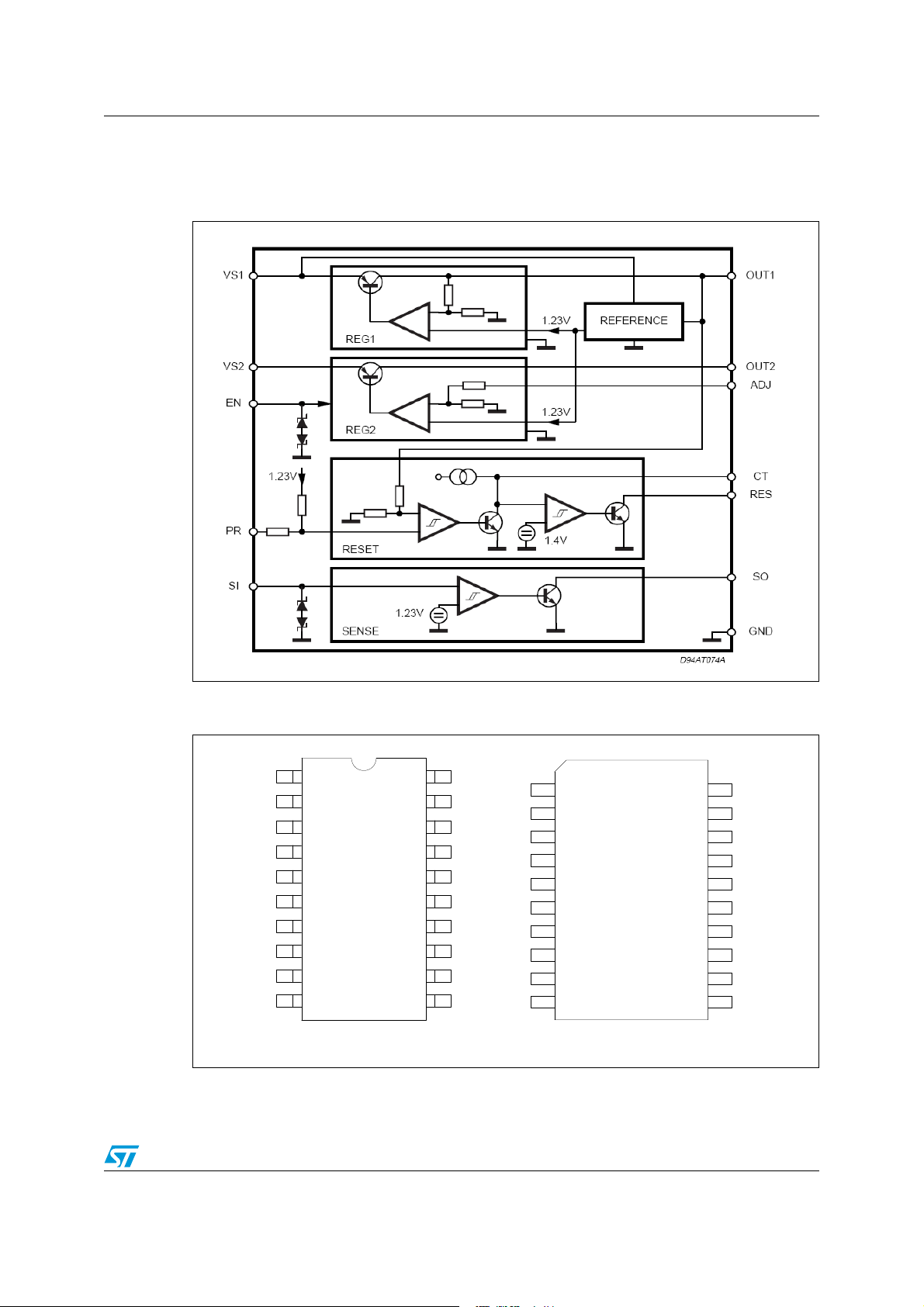
1 Block diagram and pin description
Figure 1. Block diagram
Figure 2. Configuration diagram (top view)
CT
EN
GND
GND
GND
GND
RES
SO
1
2
3
4
5
6
7
8
9
10
20
19
18
17
16
15
14
13
12
11
SIPR
V
S1
V
S2
GND
GND
GND
GND
N.C.
OUT2
ADJOUT1
N.C.
GND
SO-20
1
2
V
S2
V
S1
SI
PR
CT
EN
3
4
5
6
7
8
9
10
20
19
18
17
16
15
14
13
12
11
GNDGND
N.C.N.C.
OUT2
ADJ
OUT1
SO
RESET
N.C.
N.C.
GND
PowerSO-20
Doc ID 17243 Rev 1 5/20
Block diagram and pin description L4938ED, L4938EPD
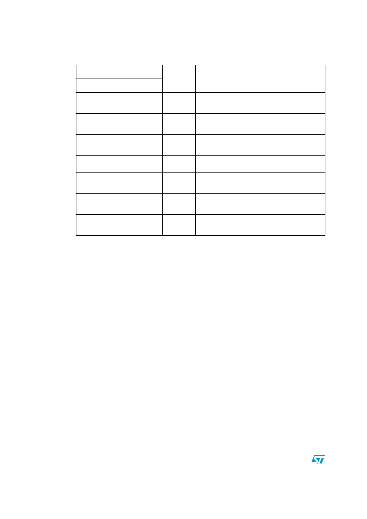
Table 2. Pin definitions and functions
PIn number
Name Function
SO-20 PowerSO-20
18 3 V
19 4 V
Supply voltage (400 mA regulator)
S2
Supply voltage (100 mA regulator, reset, sense)
S1
20 5 SI Sense input
1 6 PR Reset threshold programming
2 7 CT Reset delay capacitor
3 8 EN Enable (low activates the 400 mA regulator)
4, 5, 6, 7, 14, 15,
16, 17
1, 10, 11, 20 GND Ground
8 14 RES Reset output
9 15 SO Sense output
10 16 OUT1 100 mA regulator output
11 17 ADJ Feedback of 400 mA regulator
12 18 OUT2 400 mA regulator output
13 2, 9, 19 NC Not connected
6/20 Doc ID 17243 Rev 1
 Loading...