

Page 1
AN3992
MS19972V1
ISO15693 RF
STM8L162M8
Plain data
Encrypted data
CR95HF
LRxk
contactless tag
ISO/IEC 15693 RF
transaction
SPI or UART bus
AES hardware
RF communication
Application note
Using an STM8L162M8 AES hardware accelerator with a CR95HF
to encrypt contactless tag data memory
Introduction
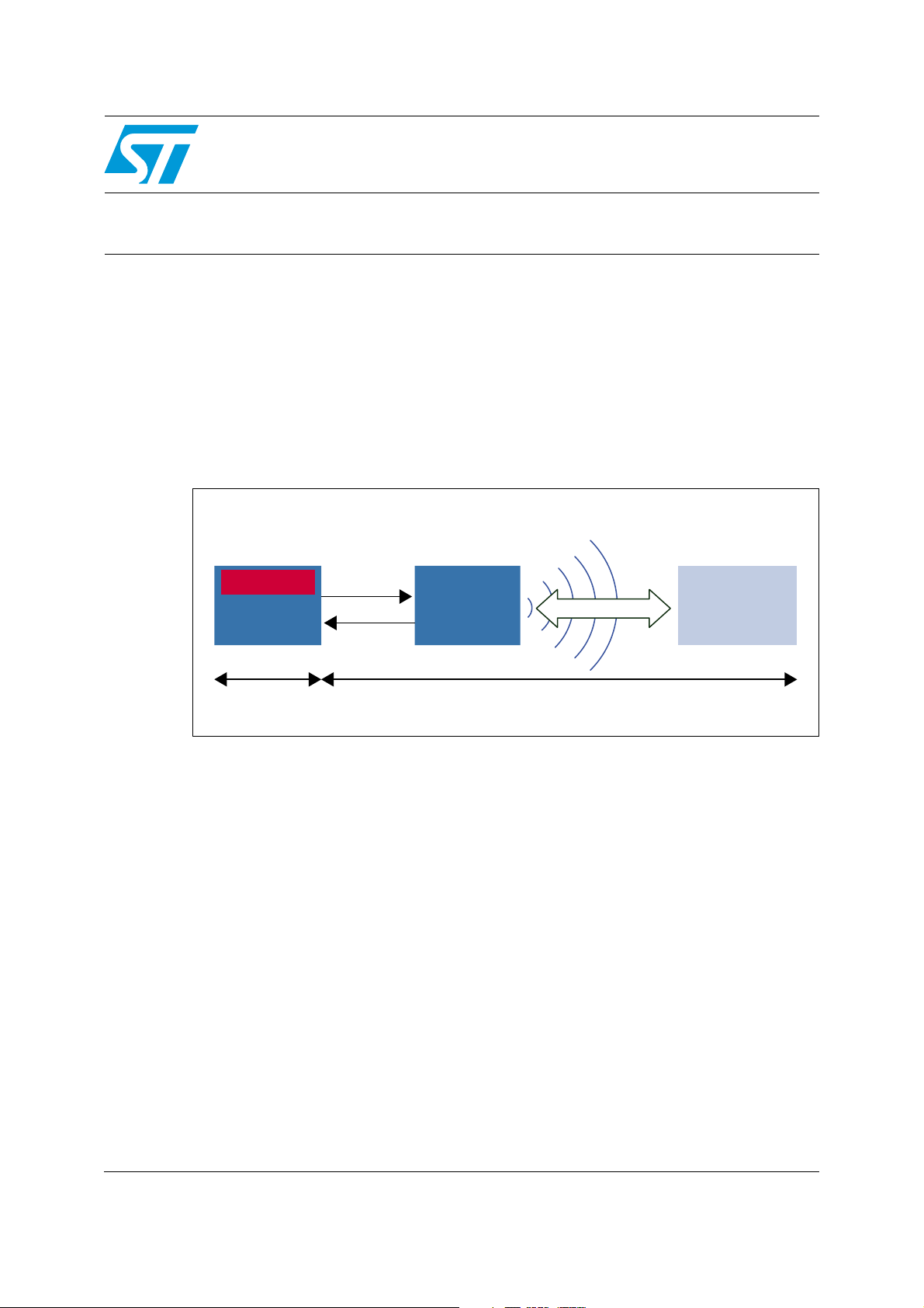
This application note describes STM8L162M8 demonstration firmware which reads and
writes encrypted data into an LRxk contactless tag. The MCU encrypts data using its
embedded AES hardware and sends it to a contactless tag through the CR95HF
transceiver.
The data stored into the contactless tag can be read by anyone but decrypted only by the
encryption or decryption key owner.
Figure 1. Data encryption diagram
April 2012 Doc ID 022369 Rev 3 1/22
www.st.com
Page 2

Contents AN3992
Contents
1 Acronyms and notational conventions . . . . . . . . . . . . . . . . . . . . . . . . . . 5
1.1 List of terms . . . . . . . . . . . . . . . . . . . . . . . . . . . . . . . . . . . . . . . . . . . . . . . . 5
1.2 Notational conventions . . . . . . . . . . . . . . . . . . . . . . . . . . . . . . . . . . . . . . . . 5
1.2.1 Binary number representation . . . . . . . . . . . . . . . . . . . . . . . . . . . . . . . . . 5
1.2.2 Hexadecimal number representation . . . . . . . . . . . . . . . . . . . . . . . . . . . . 5
1.2.3 Decimal number representation . . . . . . . . . . . . . . . . . . . . . . . . . . . . . . . . 6
2 Overview . . . . . . . . . . . . . . . . . . . . . . . . . . . . . . . . . . . . . . . . . . . . . . . . . . 7
2.1 AES cryptography overview . . . . . . . . . . . . . . . . . . . . . . . . . . . . . . . . . . . . 7
2.2 CR95HF overview . . . . . . . . . . . . . . . . . . . . . . . . . . . . . . . . . . . . . . . . . . . 7
2.3 STM8L162M8 overview . . . . . . . . . . . . . . . . . . . . . . . . . . . . . . . . . . . . . . . 7
3 Firmware description . . . . . . . . . . . . . . . . . . . . . . . . . . . . . . . . . . . . . . . . 8
3.1 AES hardware . . . . . . . . . . . . . . . . . . . . . . . . . . . . . . . . . . . . . . . . . . . . . . 8
3.2 AES encryption mode . . . . . . . . . . . . . . . . . . . . . . . . . . . . . . . . . . . . . . . . 9
3.3 Key derivation mode . . . . . . . . . . . . . . . . . . . . . . . . . . . . . . . . . . . . . . . . . 10
3.4 Key derivation and decryption mode . . . . . . . . . . . . . . . . . . . . . . . . . . . . 11
4 Application setup . . . . . . . . . . . . . . . . . . . . . . . . . . . . . . . . . . . . . . . . . . 12
4.1 Hardware . . . . . . . . . . . . . . . . . . . . . . . . . . . . . . . . . . . . . . . . . . . . . . . . . 12
4.1.1 STM8L162M8 microcontroller . . . . . . . . . . . . . . . . . . . . . . . . . . . . . . . . 12
4.1.2 STM8L1528_EVAL evaluation board . . . . . . . . . . . . . . . . . . . . . . . . . . . 12
4.2 CR95HF plug board . . . . . . . . . . . . . . . . . . . . . . . . . . . . . . . . . . . . . . . . . 13
4.3 Software . . . . . . . . . . . . . . . . . . . . . . . . . . . . . . . . . . . . . . . . . . . . . . . . . . 14
4.3.1 ST Visual Develop . . . . . . . . . . . . . . . . . . . . . . . . . . . . . . . . . . . . . . . . . 14
4.3.2 Cosmic compiler . . . . . . . . . . . . . . . . . . . . . . . . . . . . . . . . . . . . . . . . . . 14
4.3.3 HyperTerminal . . . . . . . . . . . . . . . . . . . . . . . . . . . . . . . . . . . . . . . . . . . . 14
4.4 Project . . . . . . . . . . . . . . . . . . . . . . . . . . . . . . . . . . . . . . . . . . . . . . . . . . . 14
4.5 Pinout description . . . . . . . . . . . . . . . . . . . . . . . . . . . . . . . . . . . . . . . . . . . 15
4.5.1 Communication with CR95HF I/Os . . . . . . . . . . . . . . . . . . . . . . . . . . . . 15
4.6 Contactless tag layout . . . . . . . . . . . . . . . . . . . . . . . . . . . . . . . . . . . . . . . 15
4.7 Using the software implementation of AES chaining modes . . . . . . . . . . 16
4.7.1 HyperTerminal welcome screen . . . . . . . . . . . . . . . . . . . . . . . . . . . . . . . 17
2/22 Doc ID 022369 Rev 3
Page 3

AN3992 Contents
4.7.2 Contactless tag memory initialization screen . . . . . . . . . . . . . . . . . . . . . 17
4.7.3 Reading contactless tag memory screen . . . . . . . . . . . . . . . . . . . . . . . . 18
4.7.4 Encrypting contactless tag memory screen . . . . . . . . . . . . . . . . . . . . . . 18
4.7.5 Decrypting contactless tag memory screen . . . . . . . . . . . . . . . . . . . . . . 19
5 Additional recommendations . . . . . . . . . . . . . . . . . . . . . . . . . . . . . . . . . 20
5.1 Firmware . . . . . . . . . . . . . . . . . . . . . . . . . . . . . . . . . . . . . . . . . . . . . . . . . 20
5.2 Direct memory access (DMA) . . . . . . . . . . . . . . . . . . . . . . . . . . . . . . . . . 20
5.3 Encryption and decryption keys . . . . . . . . . . . . . . . . . . . . . . . . . . . . . . . . 20
5.4 Block padding . . . . . . . . . . . . . . . . . . . . . . . . . . . . . . . . . . . . . . . . . . . . . . 20
6 Revision history . . . . . . . . . . . . . . . . . . . . . . . . . . . . . . . . . . . . . . . . . . . 21
Doc ID 022369 Rev 3 3/22
Page 4
List of figures AN3992
List of figures
Figure 1. Data encryption diagram. . . . . . . . . . . . . . . . . . . . . . . . . . . . . . . . . . . . . . . . . . . . . . . . . . . . 1
Figure 2. AES hardware accelerator . . . . . . . . . . . . . . . . . . . . . . . . . . . . . . . . . . . . . . . . . . . . . . . . . . 8
Figure 3. AES hardware accelerator: encryption mode . . . . . . . . . . . . . . . . . . . . . . . . . . . . . . . . . . . . 9
Figure 4. AES hardware accelerator: key derivation mode . . . . . . . . . . . . . . . . . . . . . . . . . . . . . . . . 10
Figure 5. AES hardware accelerator: key derivation and decryption mode . . . . . . . . . . . . . . . . . . . . 11
Figure 6. STM8L1528_EVAL board (Rev. A) connectors . . . . . . . . . . . . . . . . . . . . . . . . . . . . . . . . . 12
Figure 7. PLUG-CR95HF-B Board I/Os . . . . . . . . . . . . . . . . . . . . . . . . . . . . . . . . . . . . . . . . . . . . . . . 13
Figure 8. Workspace organization . . . . . . . . . . . . . . . . . . . . . . . . . . . . . . . . . . . . . . . . . . . . . . . . . . . 14
Figure 9. Application flow chart . . . . . . . . . . . . . . . . . . . . . . . . . . . . . . . . . . . . . . . . . . . . . . . . . . . . . 16
Figure 10. HyperTerminal welcome screen . . . . . . . . . . . . . . . . . . . . . . . . . . . . . . . . . . . . . . . . . . . . . 17
Figure 11. Contactless tag memory initialization screen . . . . . . . . . . . . . . . . . . . . . . . . . . . . . . . . . . . 17
Figure 12. Reading contactless tag memory screen . . . . . . . . . . . . . . . . . . . . . . . . . . . . . . . . . . . . . . 18
Figure 13. Encrypting contactless tag memory screen . . . . . . . . . . . . . . . . . . . . . . . . . . . . . . . . . . . . 18
Figure 14. Decrypting contactless tag memory screen . . . . . . . . . . . . . . . . . . . . . . . . . . . . . . . . . . . . 19
4/22 Doc ID 022369 Rev 3
Page 5
AN3992 Acronyms and notational conventions
1 Acronyms and notational conventions
1.1 List of terms
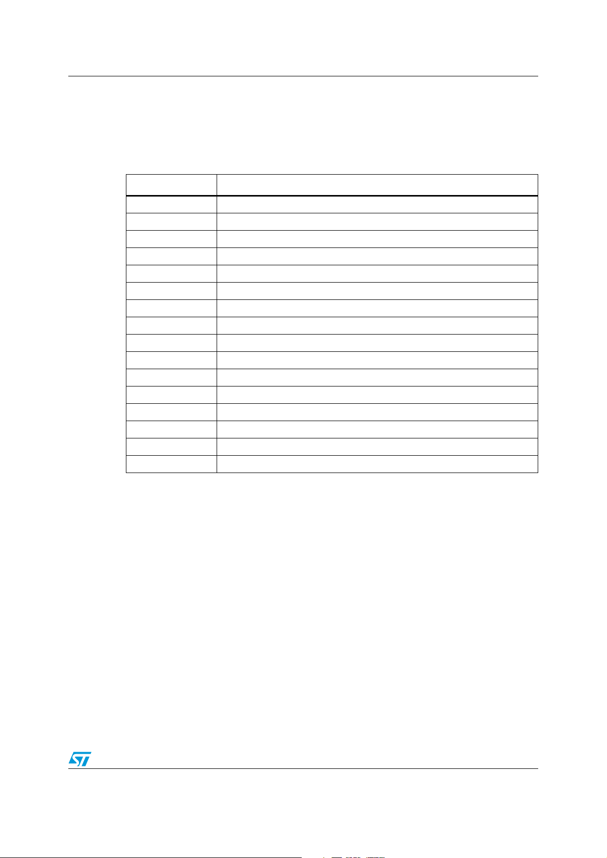
Table 1. List of terms
Acronyms Definitions
ADC Analog to Digital Converter
CISC Complex Instruction Set Computer
DAC Digital to Analog Converter
EEPROM Electrically Erasable Programmable Read-Only Memory
IC Integrated Circuit
IEC International Electrotechnical Commission
ISO International Organization for Standardization
LED Light Emitting Diode
LCD Liquid Crystal Display
FIPS Federal Information Processing Standard
MIPS Million Instructions Per Second
NFC Near Field Communication
RF Radio Frequency
RFID Radio Frequency Identification
SPI Serial Peripheral Interface
USART Universal Synchronous/Asynchronous Receiver/Transmitter
1.2 Notational conventions
The following conventions and notations apply in this document unless otherwise stated.
1.2.1 Binary number representation
Binary numbers are represented by strings of digits 0 and 1, with the Most Significant Bit
(MSB) on the left, the Least Significant Bit (LSB) on the right, and “0b” added at the
beginning.
For example: 0b11110101
1.2.2 Hexadecimal number representation
Hexadecimal numbers are represented by numbers 0 to 9, characters A - F, and “0x” added
at the beginning. The Most Significant Byte (MSB) is shown on the left and the Least
Significant Byte (LSB) on the right.
For example: 0xF5
Doc ID 022369 Rev 3 5/22
Page 6

Acronyms and notational conventions AN3992
1.2.3 Decimal number representation
Decimal numbers are represented as is, without any trailing character.
For example: 245
6/22 Doc ID 022369 Rev 3
Page 7

AN3992 Overview
2 Overview
2.1 AES cryptography overview
The purpose of cryptography is to protect sensitive data to avoid it from being read by
unauthorized persons. There are many algorithms that implement cryptography. These
techniques can be split into:
● Asymmetric cryptography algorithms: These algorithms use a key to encrypt and
another key to decrypt messages. RSA and DSA are examples of this type of
algorithm.
● Symmetric cryptography algorithms: These algorithms use the same key to encrypt
and decrypt messages. Advanced Encryption Standard (AES), Data Encryption
Standard (DES) are examples of this type of algorithm.
The Advanced Encryption Standard (AES) specifies a FIPS-approved cryptography
algorithm that can be used to protect electronic data. AES exists in three versions: 128-bit,
192-bit and 256-bit.
2.2 CR95HF overview
The CR95HF device is an RF transceiver IC for contactless application (ISO/IEC 15693,
ISO/IEC 14443-3 and ISO/IEC 18092). It manages the RF communication with RFID or
NFC contactless tags. It includes frame coding, RF modulation and contactless tag
response decoding.
The CR95HF is a slave device. A host (such as an MCU) is required to control it.
2.3 STM8L162M8 overview
High-density STM8L162M8 microcontrollers have an embedded AES 128-bit hardware
accelerator to off-load the CPU from encryption or decryption tasks. This AES peripheral is
a fully compliant implementation of the AES standard as defined by the FIPS publication
(FIPS PUB 197, 2001 November 26).
This application note applies to STM8L162M8 high-density devices with built-in AES
peripheral. The software supplied with this application note provides an implementation of
some commonly used AES chaining modes (ECB, CBC, CFB, OFB and CTR).
For more detailed information, you should refer to the AES section of the STM8L15x and
STM8L16x microcontroller family reference manual (RM0031).
Doc ID 022369 Rev 3 7/22
Page 8

Firmware description AN3992
MS19976V1
CR95HF and STM8L
AES hardware accelerator
128-bit cipher text
128-bit plain text
♫σCΣm2DM5kìL"ß▀⌠
Key
3 Firmware description
3.1 AES hardware
The Advanced Encryption Standard (AES) hardware accelerator can be used to encrypt
(encipher) and decrypt (decipher) 128-bit blocks using a 128-bit key length.
Figure 2. AES hardware accelerator
The AES hardware accelerator provides four modes of operation:
1. Encryption mode
2. Decryption mode (using decryption key)
3. Key derivation mode
4. Key derivation and decryption mode (using encryption key)
8/22 Doc ID 022369 Rev 3
Page 9
AN3992 Firmware description
MS19975V1
CR95HF and STM8L
AES hardware accelerator
Encryption mode
128-bit cipher text
128-bit plain text
♫σCΣm2DM5kìL"ß▀⌠
Encryption Key:
"ultra-low power.”
3.2 AES encryption mode
In this mode, the AES accelerator performs the encryption of a 128-bit plain text using the
provided 128-bit key to compute the cipher text. In the example below, the plain text
“CR95HF and STM8L” is encrypted using the “Ultralow Power” key.
The cipher text, computed by the AES hardware accelerator, is:
● in ASCII format: ♫σCΣm2DM5kìL″ß▀⌠
● in hex format: 0E E5 43 E4 6D 32 44 4D 35 6B 8D 05 4C 22 DF F4
(according to “code page 437").
See http://en.wikipedia.org/wiki/Code_page_437
Figure 3. AES hardware accelerator: encryption mode
Doc ID 022369 Rev 3 9/22
Page 10

Firmware description AN3992
MS19718V1
AES hardware accelerator:
key derivation mode
Encryption Key=
"ultra-low power.”
Decryption Key=
"91 DF 30 53 7A E9 49 19
92 FF 8D F8 C4 9B B7 4D”
3.3 Key derivation mode
AES is a symmetric cryptography algorithm. The AES hardware accelerator can compute a
derived key from an encryption key that is named “Decryption key”. The decryption key is
pre-computed to speed-up the decryption phase.
In this mode, the AES takes the encryption key as an input and provides the decryption key
as an output. This mode takes 320 clock cycles.
Figure 4. AES hardware accelerator: key derivation mode
In the example above, the decryption key, computed from the “Ultralow Power” encryption
key, is “91 DF 30 53 7A E9 49 19 92 FF 8D F8 C4 9B B7 4D" (hex format).
The algorithm given in Figure 5 provides the steps needed to use the AES hardware.
10/22 Doc ID 022369 Rev 3
Page 11

AN3992 Firmware description
0E E5 43 E4 6D 32 44 4D
35 6B 8D 05 4C 22 DF F4
Decryption Key=
"91 DF 30 53 7A E9 49 19
92 FF 8D F8 C4 9B B7 4D”
AES hardware accelerator
decryption mode
128-bit cipher text
CR95HF and STM8L
128-bit cipher text
MS19974V1
3.4 Key derivation and decryption mode
When this mode is selected, the AES hardware accelerator performs the decryption of a
128-bit cipher text using the provided 128-bit encryption key to compute the plain text. In the
example below, the cipher text is “22 F6 21 81 F8 AF C0 FE 03 36 B8 95 72 CB
D1 A8" and the encryption key is "ultra-low power.". The plain text, computed by the AES
hardware accelerator, is "STM32L and STM8L".
Figure 5. AES hardware accelerator: key derivation and decryption mode
Doc ID 022369 Rev 3 11/22
Page 12

Application setup AN3992
In the STM8L1528-EVAL board
REV A, the MCU is replaced by
STM8L162M8T6 device
USB connector used to
supply the board and
program the STM8L
RS232 connector for
communication with
HyperTerminal
4 Application setup
4.1 Hardware
4.1.1 STM8L162M8 microcontroller
High-density STM8L162M8 Ultralow power devices feature an enhanced STM8 CPU core
providing increased processing power (up to 16 MIPS at 16 MHz) while maintaining the
advantages of a CISC architecture with improved code density, a 24-bit linear addressing
space and an optimized architecture for low power operations.
All high-density STM8L162M8 microcontroller features include data EEPROM and low
power low-voltage single-supply program Flash memory.
The devices incorporate an extensive range of enhanced I/Os and peripherals, a 12-bit
ADC, two DACs, two comparators, a real-time clock, an AES, 8x40 or 4x44-segment LCD,
four 16-bit timers, one 8-bit timer, as well as standard communication interfaces such as two
SPIs, an I2C interface, and three USARTs. The modular design of the peripheral set allows
the same peripherals to be found in different ST microcontroller families including 32-bit
families.
The STM8L162M8 can be used with the STM8L1528_EVAL board.
4.1.2 STM8L1528_EVAL evaluation board
Figure 6. STM8L1528_EVAL board (Rev. A) connectors
The STM8L1528-EVAL evaluation board is designed as a complete demonstration and
development platform for the STM8 core based STM8L152M8T6 microcontroller with an I2C
interface, 2 SPI channels, 3 USART channels, a 12-bit ADC, two 12-bit DACs, an LCD
driver, an internal SRAM, data EEPROM and Flash program memory as well as SWIM
debugging support.
The full range of hardware features on the board is provided to help you evaluate all the
MCU peripherals (motor control, USART, microphone, audio DAC, LCD, IR LED, IrDA, SPI
Flash, MicroSD card, temperature sensor, EEPROM… etc.) and develop your own
applications. Extension headers make it possible to easily connect a daughter board or
wrapping board for your specific applications.
12/22 Doc ID 022369 Rev 3
Page 13

AN3992 Application setup
CR95HF I
RQ_OUT
NSS
MOSI
VPS & VPS_TX
CR95HF IRQ_IN
MISO
SCK
GND
An ST-LINK V2 is integrated on the board as an embedded in-circuit debugger and
programmer for the STM8 MCU.
Important note
The STM8L1528_EVAL is delivered with an STM8L152M8T6 device and the firmware
designed for STM8L162M8T6. Both chips are pin-to-pin compatible but only the STM8L162
includes the AES hardware.
4.2 CR95HF plug board
The PLUG-CR95HF-B is a board which includes a CR95HF device and a matched antenna.
A host configured as a master can communicate with CR95HF through the SPI bus.
The PLUG-CR95HF-B is powered through the VPS pin and no external power supply is
required. It includes a CR95HF contactless transceiver, a 47 x 34 mm 13.56 MHz inductive
etched antenna and its associated tuning components.
Figure 7. PLUG-CR95HF-B Board I/Os
Doc ID 022369 Rev 3 13/22
Page 14

Application setup AN3992
4.3 Software
4.3.1 ST Visual Develop
ST Visual Develop (STVD) provides an easy-to-use, efficient environment for start-to-finish
control of application development (from building and debugging the application code to
programming the microcontroller).
STVD is available on STM web site http://www.st.com/internet/evalboard/product/210567.jsp
4.3.2 Cosmic compiler
Cosmic is the compiler toolchain used by ST Visual Develop. There is a 1 year free license
limited to 32 Kbytes of code and data which requires registration.
For further information about the license, refer to the Cosmic Software website.
4.3.3 HyperTerminal
HyperTerminal is a program available on Windows OS that you can use to connect to other
computers, Telnet sites, bulletin board systems (BBSs), online services, and host
computers, using either your modem or a null modem cable.
4.4 Project
The project was built from MCD standard library which is included in the
STM8L15x_StPeriph_Driver folder.
There are three steps to open the project:
1. Launch ST Visual Develop.
2. In the “File” menu, click on “Open WorkSpace”.
3. Locate the project folder and select the CR95HF_STM8L.stw file.
The project folder has been organized as the project and follows the layer organization of
the libraries.
Figure 8. Workspace organization
14/22 Doc ID 022369 Rev 3
Page 15

AN3992 Application setup
4.5 Pinout description
Ta bl e 2 describes the I/Os used and their configurations for the two boards.
4.5.1 Communication with CR95HF I/Os
Table 2. Communication with CR95HF I/Os
SPI
STM8L_EVAL
board pin
PB7 MISO Input Floating No interrupt
PB6 MOSI Output Push-Pull 10 MHz
PB5 SCK Output Push-Pull 10 MHz
PB4 NSS Output Open drain 2 MHz
PC2 IRQ_in Input Pull-up No interrupt
PC3 IRQ_out Output Open drain 2 MHz
1. Direction Data Register
2. Control Register 1
3. Control Register 2
Name
Direction Configuration
DDR
(1)
CR1
(2)
CR2
(3)
Note: In low Power state, PC2 is set with Interrupt. All pins are named from STM8L point of view.
4.6 Contactless tag layout
In this demonstration application, the plain text and the encrypted text are stored into the
memory of the contactless tag. The locations of these fields are defined in the application.
The sizes of plain text and cipher text are 128 bits.
Table 3. Field layout
Block Byte 0 Byte 1 Byte 2 Byte 3
0
1
2
3
4
5
6
7
Plain text
Cipher text
Doc ID 022369 Rev 3 15/22
Page 16

Application setup AN3992
MS19973V1
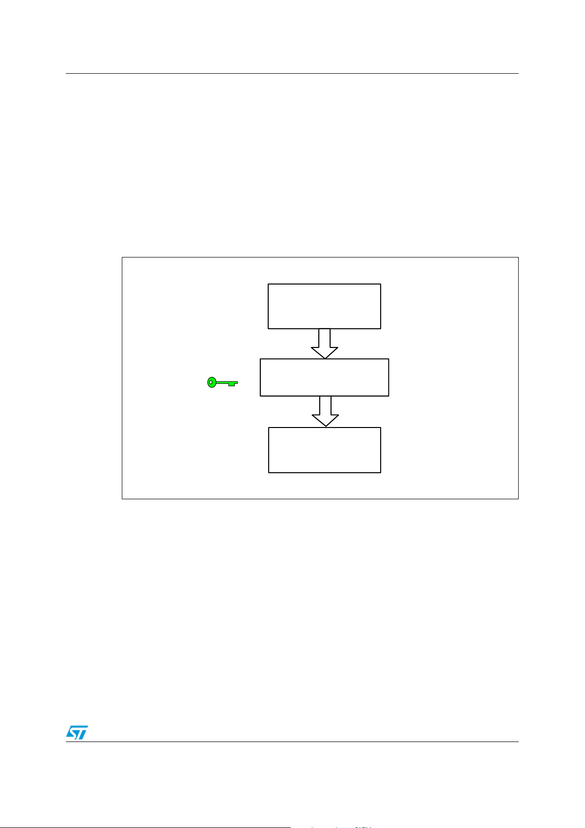
Start
END
Display on hyper terminal (1)
Initialize Contactless tag Display on hyper terminal (2)
Display on hyper terminal (3)
Is a tag present?
No
Yes
Read 128 bits from tag
Display on hyper terminal (4)Write the cypher text
Read the cypher text
Display on hyper terminal (5)Decrypt
Encrypt
Is a tag present?
No
Yes
4.7 Using the software implementation of AES chaining modes
This firmware example both encrypts and decrypts the memory contents of a contactless tag.
The plain text is read from the contactless tag and encrypted by using the AES hardware
included in the STM8L162M8 device. The cipher text is sent to the CR95HF through the SPI
bus and transmitted to the contactless tag.
The encryption and decryption keys are stored in the EEPROM data of the
device.
Figure 9 presents the main functions.
Figure 9. Application flow chart
STM8L162M8
16/22 Doc ID 022369 Rev 3
Page 17

AN3992 Application setup
Note: 1 See Chapter 4.7.1
2See Chapter 4.7.2
3See Chapter 4.7.3
4See Chapter 4.7.4
5See Chapter 4.7.5
4.7.1 HyperTerminal welcome screen
Once the STM8L_EVAL board is powered up, the HyperTerminal screen displays the
following text.
Figure 10. HyperTerminal welcome screen
4.7.2 Contactless tag memory initialization screen
The user shall place an ISO/IEC contactless tag close to the plug board antenna. When the
CR895HF device detects the contactless tag, the first memory rows will be programmed
with the following ASCII text (128 bits): "CR95HF and STM8L".
When the contactless tag memory is correctly initialized, the HyperTerminal screen displays
the following text.
Figure 11. Contactless tag memory initialization screen
Doc ID 022369 Rev 3 17/22
Page 18

Application setup AN3992
4.7.3 Reading contactless tag memory screen
The next step of the example is to read the plain text from the contactless tag. It shall be
"CR95HF and STM8L".
Figure 12. Reading contactless tag memory screen
4.7.4 Encrypting contactless tag memory screen
The plain text is encrypted by using the cipher key defined, written into the STM8L162M8
device.
Figure 13. Encrypting contactless tag memory screen
The cipher text is written into the contactless tag memory after the plain text (refer to
Chapter 4.6).
18/22 Doc ID 022369 Rev 3
Page 19
AN3992 Application setup
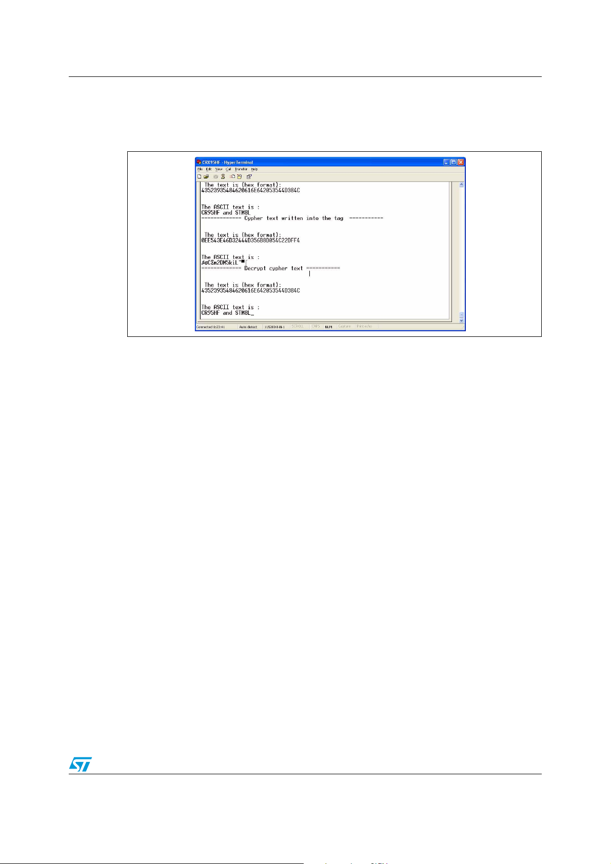
4.7.5 Decrypting contactless tag memory screen
The cipher text is read from the contactless tag and decoded by using the decryption key.
Figure 14. Decrypting contactless tag memory screen
Doc ID 022369 Rev 3 19/22
Page 20

Additional recommendations AN3992
5 Additional recommendations
5.1 Firmware
The firmware implementation of the AES chaining modes provided with this application note
is intended to be used as a starting-point. This firmware may be tailored and simplified to
cover only the required features. For further information, refer to the AES section in the
RM0031 microcontroller reference manual.
5.2 Direct memory access (DMA)
The Direct Memory Access (DMA) can be used to handle input and output phases for better
performance, and to free the CPU for other tasks.
5.3 Encryption and decryption keys
The encryption key can be stored and protected in the EEPROM data memory. Refer to the
“Flash program memory and data EEPROM” section in the microcontroller reference
manual RM0031.
5.4 Block padding
AES-128 is a 128-bit block cryptography which means that AES encrypts a 128-bit plain text
providing a 128-bit cipher text. The text to be encrypted and decrypted can be of any length
and must be padded to get an exact multiple of a block size (128 bits) before being
processed (encrypted or decrypted).
In the following example of plain text, "The CR95HF is RF transceiver for ISO/IEC
14443, 15693 and 18092 protocols" is split into 5 blocks. The last one, since its size
is 9 bytes, is padded by seven “0”.
Padding messages with “00” are not recommended. Padding must comply with
specifications such as ANSI X.923, ISO/IEC 10126 or PKCS7.
20/22 Doc ID 022369 Rev 3
Page 21
AN3992 Revision history
6 Revision history
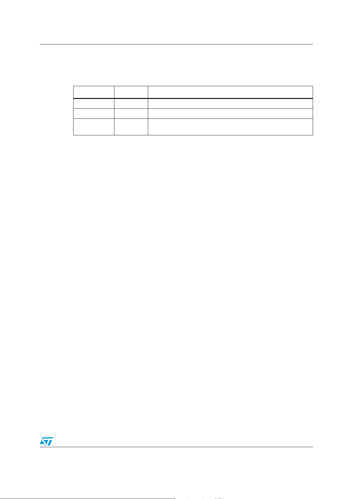
Table 4. Document revision history
Date Revision Changes
19-Dec-2011 1 Initial release.
07-Feb-2012 2 Updated Figure 7: PLUG-CR95HF-B Board I/Os on page 13.
02-Apr-2012 3
Replaced ‘LRIxk’ and ‘LRxk’ by ‘LRxk’ in the Introduction ( text and
Figure 1: Data encryption diagram).
Doc ID 022369 Rev 3 21/22
Page 22

AN3992
Please Read Carefully:
Information in this document is provided solely in connection with ST products. STMicroelectronics NV and its subsidiaries (“ST”) reserve the
right to make changes, corrections, modifications or improvements, to this document, and the products and services described herein at any
time, without notice.
All ST products are sold pursuant to ST’s terms and conditions of sale.
Purchasers are solely responsible for the choice, selection and use of the ST products and services described herein, and ST assumes no
liability whatsoever relating to the choice, selection or use of the ST products and services described herein.
No license, express or implied, by estoppel or otherwise, to any intellectual property rights is granted under this document. If any part of this
document refers to any third party products or services it shall not be deemed a license grant by ST for the use of such third party products
or services, or any intellectual property contained therein or considered as a warranty covering the use in any manner whatsoever of such
third party products or services or any intellectual property contained therein.
UNLESS OTHERWISE SET FORTH IN ST’S TERMS AND CONDITIONS OF SALE ST DISCLAIMS ANY EXPRESS OR IMPLIED
WARRANTY WITH RESPECT TO THE USE AND/OR SALE OF ST PRODUCTS INCLUDING WITHOUT LIMITATION IMPLIED
WARRANTIES OF MERCHANTABILITY, FITNESS FOR A PARTICULAR PURPOSE (AND THEIR EQUIVALENTS UNDER THE LAWS
OF ANY JURISDICTION), OR INFRINGEMENT OF ANY PATENT, COPYRIGHT OR OTHER INTELLECTUAL PROPERTY RIGHT.
UNLESS EXPRESSLY APPROVED IN WRITING BY TWO AUTHORIZED ST REPRESENTATIVES, ST PRODUCTS ARE NOT
RECOMMENDED, AUTHORIZED OR WARRANTED FOR USE IN MILITARY, AIR CRAFT, SPACE, LIFE SAVING, OR LIFE SUSTAINING
APPLICATIONS, NOR IN PRODUCTS OR SYSTEMS WHERE FAILURE OR MALFUNCTION MAY RESULT IN PERSONAL INJURY,
DEATH, OR SEVERE PROPERTY OR ENVIRONMENTAL DAMAGE. ST PRODUCTS WHICH ARE NOT SPECIFIED AS "AUTOMOTIVE
GRADE" MAY ONLY BE USED IN AUTOMOTIVE APPLICATIONS AT USER’S OWN RISK.
Resale of ST products with provisions different from the statements and/or technical features set forth in this document shall immediately void
any warranty granted by ST for the ST product or service described herein and shall not create or extend in any manner whatsoever, any
liability of ST.
ST and the ST logo are trademarks or registered trademarks of ST in various countries.
Information in this document supersedes and replaces all information previously supplied.
The ST logo is a registered trademark of STMicroelectronics. All other names are the property of their respective owners.
© 2012 STMicroelectronics - All rights reserved
STMicroelectronics group of companies
Australia - Belgium - Brazil - Canada - China - Czech Republic - Finland - France - Germany - Hong Kong - India - Israel - Italy - Japan -
Malaysia - Malta - Morocco - Philippines - Singapore - Spain - Sweden - Switzerland - United Kingdom - United States of America
www.st.com
22/22 Doc ID 022369 Rev 3
 Loading...