

Page 1

AN3991
Application note
How to drive multiple stepper motors with the L6470 motor driver
Introduction
The L6470 is a flexible device for the driving of bipolar stepper motors in multiple motor
systems. This application note describes how to drive three bipolar stepper motors in a
daisy chain configuration. Each motor position and its velocity can be controlled individually
or a sequence of position and velocity commands can be implemented by using the
IronPython scripting language included in the dSPIN evaluation tool. With the dSPIN
evaluation tool and STEVAL-PCC009V2 interface board, up to eight stepper motors can be
controlled in a daisy chain configuration.
March 2012 Doc ID 022332 Rev 1 1/20
www.st.com
Page 2

Contents AN3991
Contents
1 Hardware requirements . . . . . . . . . . . . . . . . . . . . . . . . . . . . . . . . . . . . . . 4
2 Software requirements . . . . . . . . . . . . . . . . . . . . . . . . . . . . . . . . . . . . . . . 5
3 Software installation . . . . . . . . . . . . . . . . . . . . . . . . . . . . . . . . . . . . . . . . . 5
4 Interconnection diagram . . . . . . . . . . . . . . . . . . . . . . . . . . . . . . . . . . . . . 6
5 Stepper motor characterization . . . . . . . . . . . . . . . . . . . . . . . . . . . . . . . . 7
6 Running the motor evaluation . . . . . . . . . . . . . . . . . . . . . . . . . . . . . . . . . 7
7 Controlling three motors individually . . . . . . . . . . . . . . . . . . . . . . . . . . . 8
7.1 Individual motor position control . . . . . . . . . . . . . . . . . . . . . . . . . . . . . . . . . 8
7.2 Individual motor speed control . . . . . . . . . . . . . . . . . . . . . . . . . . . . . . . . . . 8
8 Controlling three motors with scripts . . . . . . . . . . . . . . . . . . . . . . . . . . . 9
8.1 Three_motors script text . . . . . . . . . . . . . . . . . . . . . . . . . . . . . . . . . . . . . . 10
Appendix A Additional instructions . . . . . . . . . . . . . . . . . . . . . . . . . . . . . . . . . . . 12
A.1 Communication board driver installation procedure . . . . . . . . . . . . . . . . . 12
A.2 Motor back-EMF constant (Ke) measurement. . . . . . . . . . . . . . . . . . . . . . 15
9 References . . . . . . . . . . . . . . . . . . . . . . . . . . . . . . . . . . . . . . . . . . . . . . . . 18
Revision history . . . . . . . . . . . . . . . . . . . . . . . . . . . . . . . . . . . . . . . . . . . . . . . . . . . . 19
2/20 Doc ID 022332 Rev 1
Page 3

AN3991 List of figures
List of figures
Figure 1. Daisy chain example. . . . . . . . . . . . . . . . . . . . . . . . . . . . . . . . . . . . . . . . . . . . . . . . . . . . . . . 6
Figure 2. Communication board driver installation - step 3 . . . . . . . . . . . . . . . . . . . . . . . . . . . . . . . . 12
Figure 3. Communication board driver installation - step 4 . . . . . . . . . . . . . . . . . . . . . . . . . . . . . . . . 13
Figure 4. Communication board driver installation - step 5 . . . . . . . . . . . . . . . . . . . . . . . . . . . . . . . . 13
Figure 5. Communication board driver installation - step 6 . . . . . . . . . . . . . . . . . . . . . . . . . . . . . . . . 14
Figure 6. Communication board driver installation - step 7 . . . . . . . . . . . . . . . . . . . . . . . . . . . . . . . . 14
Figure 7. Motor back-EMF constant measurement - step 1. . . . . . . . . . . . . . . . . . . . . . . . . . . . . . . . 15
Figure 8. Motor back-EMF constant measurement - step 3. . . . . . . . . . . . . . . . . . . . . . . . . . . . . . . . 15
Figure 9. Motor back-EMF constant measurement: bad back-EMF waveform . . . . . . . . . . . . . . . . . 16
Figure 10. Motor back-EMF constant measurement: good back-EMF waveform . . . . . . . . . . . . . . . . 16
Figure 11. Motor back-EMF constant measurement - step 7. . . . . . . . . . . . . . . . . . . . . . . . . . . . . . . . 17
Doc ID 022332 Rev 1 3/20
Page 4

Hardware requirements AN3991
1 Hardware requirements
Each stepper motor being evaluated requires an EVAL6470H demonstration board. Also
required is an STEVAL-PCC009V2 interface board that is connected between the PC USB
port and the first EVAL6470H. A 10-pin flat cable is needed for each EVAL6470H. A
standard USB male to mini USB male cable connects the STEVAL-PCC009V2 to the PC.
In addition to the interface boards and cables, a DC power supply with a voltage output
between 8 V and 45 V is required.
4/20 Doc ID 022332 Rev 1
Page 5

AN3991 Software requirements
2 Software requirements
The software needed is the dSPIN evaluation tool (revision 1.7 or higher) which can be
downloaded at www.st.com/dspin.
Choose L6470 in the Product Listed section, then the Design support option, software &
development tools, and then SW DEMOS.
3 Software installation
Uninstall any previous versions of the dSPIN evaluation tool.
Install the dSPIN evaluation software by clicking on setup Windows installer package.
After installation is complete, the dSPIN software tool is located at C:\Program
Files\STMicroelectronics\ dSPIN evaluation tool.
Download the Three_motors.py script from the same page where this application note can
be found.
Doc ID 022332 Rev 1 5/20
Page 6
Interconnection diagram AN3991
$0Y
,QWHUIDFH
ERDUG
67(9$/3&&9
(9$/
- -
-3
(9$/
- -
-3
7HUPLQDWLRQ
MXPSHUFORVHG
7HUPLQDWLRQ
MXPSHURSHQ
VWERDUG /DVWERDUG
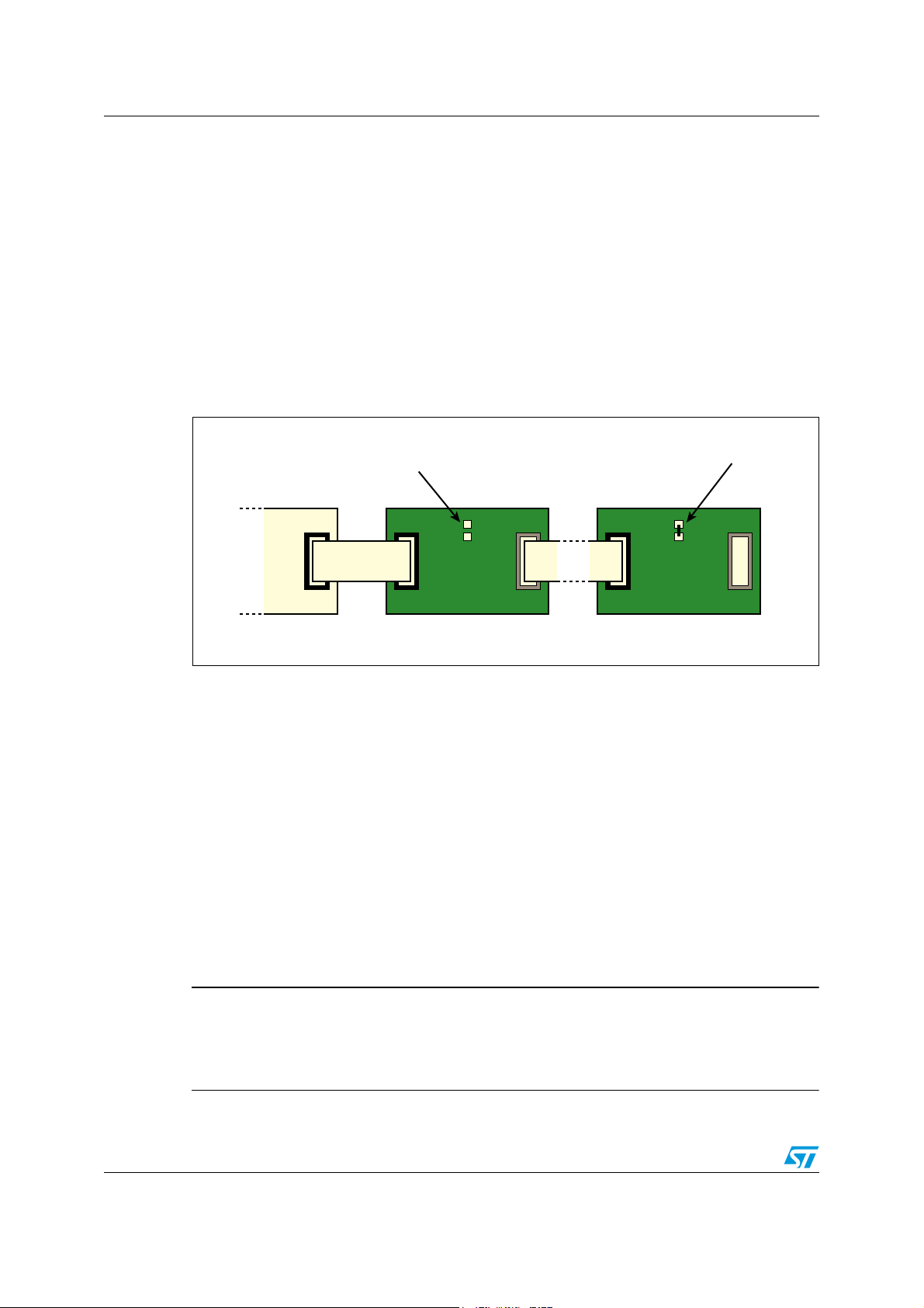
4 Interconnection diagram
With reference to the AN3103 application note, on each EVAL6470H connect the power
supply to VS and ground and connect one stepper motor coil to OUT1A and OUT2A.
Connect the other stepper motor coil to OUT1B and OUT2B.
Jumper connections: on the EVAL6470H, jumper JP2 is located between the
OUT1A/OUT2A and OUT1B/OUT2B screw connections, just below the VDD test point. In
the daisy chain connection, JP2 must be open on all EVAL6470Hs except the last one. On
the last EVAL6470H, JP2 is shorted. Additional EVAL6470H demonstration boards can be
connected in daisy chain mode. Up to eight motors can be controlled using a single
STEVAL-PCC009V2 interface board.
Figure 1. Daisy chain example
To drive two or more boards in daisy chain configuration:
1. Open the termination jumpers on all EVAL6470H demonstration boards except the last
one.
2. Verify the termination jumper of the last evaluation board is closed.
3. Plug the interface board into the PC through the USB cable.
4. If requested, install interface board drivers.
5. Connect the interface board 10-pin connector to the SPI_IN connector of the first
demonstration board.
6. Connect the SPI_OUT connector of the previous demonstration board to the SPI_IN
connector of the next one.
7. Repeat item 6 until all the others boards in the chain are connected.
Information about the termination jumper and the SPI connectors can be found in the
AN3103 application note.
Warning: Increasing the number of the devices connected in daisy
chain configuration may degrade SPI communication
performance. If communication issues are found, try to
reduce SPI clock speed.
6/20 Doc ID 022332 Rev 1
Page 7

AN3991 Stepper motor characterization
5 Stepper motor characterization
Determine Rph, the resistance per phase, and Lph, the inductance per phase for the
stepper motor. These are available from the stepper motor datasheet. These parameters
are needed to optimize the back-EMF compensation. Also needed is Ke, the motor backEMF constant. This is easily measured as described in the evaluation software help file (see
also dSPIN Ke measurement section in Section A.2 of this document).
1.8 degree (Schneider Electric M-2222-2.4S) stepper motors are used in this evaluation.
6 Running the motor evaluation
After connecting the power supply and the stepper motors, and setting JP2 on each
EVAL6470H, turn on the power supply. Run the dSPIN evaluation tool.
You can find the application shortcut in the Windows start menu:
Start|Programs|STMicroelectronics|dSPIN evaluation Tool|dSPIN evaluation tool. Select the
STEVAL-PCC009V2 interface board.
Connect the USB connector from the STEVAL-PCC009V2 into the PC’s USB port.
Complete the driver installation as described in the dSPIN evaluation tool help file or follow
the procedure indicated in Section A.1 of this document.
Click the ‘Connect Board’ button in the toolbar (or select the menu item ToolsIConnect
board). The board connection status is indicated in the lower left corner.
The positioning tab is highlighted.
Device 1 is highlighted at the top of the display. Device 1 is motor 1, the first of three motors.
Physically move the shaft of motor 1 to a position defined as ‘home’ for demonstration
purposes.
Next, implement the back-EMF compensation. Click the BEMF icon (or Tools|BEMF
compensation). Fill in the application parameters and motor parameters (Rph, Lph, Ke).
Click ‘Evaluate’, and then ‘Write’.
Doc ID 022332 Rev 1 7/20
Page 8

Controlling three motors individually AN3991
7 Controlling three motors individually
7.1 Individual motor position control
Next to ABS_POS, check the Autorefresh box. Click ‘Home’, to write the home position into
the registers.
To move a specific number of steps, e.g. 1000, type 1000 in the move box. Set the direction
forward, FW, or backward, BW. Click ‘Move’. The motor moves the requested number of
steps.
To move to an absolute position, enter the position in the GoTo box. Set the direction FW or
BW, or AUTO for the shortest path. Click ‘GoTo’. The motor moves to the requested position.
7.2 Individual motor speed control
Click the ‘Speed’ tab. Enter the speed desired in steps/sec, e.g. 500 in the run box. Click FW
or BW. Verify Autorefresh is checked.
By default, the maximum allowed speed is 991.821 steps/sec. If it is necessary to run faster,
click the ‘Device Configuration’ icon (or Tools|Device configuration), change max. speed to a
higher number, and click ‘Write Configuration’ to write the new data into the registers.
Back on the home screen, click ‘Run’ and confirm that the motor shaft is running at the
desired speed. A measurement of the shaft speed can be found in the SPEED box.
To stop the motor, click HardStop, HardHiZ, SoftStop or SoftHiZ. HardStop immediately
stops the motor and keeps the L6470 internal MOSFETs on. In this case, the shaft is locked.
HardHiZ immediately stops the motor and the internal MOSFETs are off. The shaft can be
freely turned. SoftStop stops the motor under programmed deceleration set in the device
configuration section. (Tools|Device configuration). The L6470 internal MOSFETs are on
and the shaft is locked. SoftHiZ stops the motor under controlled deceleration and the
internal MOSFETs are off. The shaft can be easily turned.
To individually operate motor 2 or motor 3, click the ‘Device 2’ or ‘Device 3’ buttons on the
top of the form. Repeat the preceding procedure.
If, for example, motor 1 is running at its programmed speed and control is given to motor 2,
motor 1 continues under its existing program. Motor 1, motor 2 and motor 3 are all controlled
independently.
8/20 Doc ID 022332 Rev 1
Page 9

AN3991 Controlling three motors with scripts
8 Controlling three motors with scripts
The dSPIN evaluation tool includes a scripting environment where commands can be
written in the program and immediately executed by running the script. In the scripting
environment the devices (and then the motors) are numbered using a zero based indexing
(i.e. motor 1 becomes motor 0, motor 2 becomes motor 1, etc.). As an example of how three
motors can be controlled, the script Three_motors.py performs the following sequence:
1. Establishes the home position for all three motors wherever the shafts happen to be.
2. Spins motor 0 FW (forward) at 800 steps/sec for 5 seconds.
3. Waits 2 seconds.
4. Moves motor 0 B 2 revs or 400 steps, or 51,200 microsteps.
5. Waits 2 seconds.
6. Spins motor 1 BW (in the opposite direction) at 500 steps/sec for 8 seconds.
7. Waits 4 seconds.
8. Moves motor 1 FW 4 revs or 800 steps, or 102,400 microsteps.
9. Spins motor 2 at FW 750 steps/sec for 2 seconds.
10. Waits 1 second.
11. Moves motor 2 FW 3.5 revs or 700 steps, or 89,600 microsteps.
12. Moves all three motors in the shortest direction to their home position.
●
To run the script
– Click the ‘Script Editor’ icon (or select the menu item: Tools|Script editor)
– Click the ‘Open’ icon
– Select Three_motors.py
– Click ‘Open’
●
Three_motors.py is loaded.
– Click ‘Script’
– Click ‘Run’ script
All three motors execute their position and speed commands as previously described.
The text of Three_motors.py is attached as Three_motors.doc.
To run the motors at different speeds or move to different positions, save Three_motors.py
under a different file name, edit the script to the new requirements and run the new script.
Doc ID 022332 Rev 1 9/20
Page 10

Controlling three motors with scripts AN3991
8.1 Three_motors script text
MOTOR_A = 0 # Motor A is the 1st one
MOTOR_B = 1 # Motor B is the 2nd one
MOTOR_C = 2 # Motor C is the 3rd one
#1.Establish the home position for all three motors wherever the shafts
happen to be
# Set motor A home position
ResetPos(MOTOR_A)
# Set motor B home position
#ResetPos(MOTOR_B)
# Set motor C home position
ResetPos(MOTOR_C)
#2.Spin MOTOR_A FW (forward) at 800 steps/sec for 5 seconds
# Send the Run command
# Device Dir Speed
Run(MOTOR_A, True, 0xD1B7)
# Wait (about) 5 seconds
Delay(5000) # milliseconds
# Stop the motor
HardStop(MOTOR_A)
#3.Wait (about) 2 seconds
Delay(2000) # milliseconds
#4.Move MOTOR_A BW 2 revs or 400 steps or 51,200 microsteps
# Send the Move command
# Device Dir microSteps
Move(MOTOR_A, False, 0xC800)
Delay(2000)
#5.Spin MOTOR_B BW (in the opposite direction) at 500 steps/sec for 8
seconds
# Send the Run command
# Device Dir Speed
Run(MOTOR_B, False, 0x8312)
# Wait (about) 8 seconds
Delay(8000) # milliseconds
# Stop the motor
HardStop(MOTOR_B)
#6.Wait (about) 4 seconds
Delay(4000) # milliseconds
#7.Move MOTOR_B FW 4 revs or 800 steps or 102400 microsteps
10/20 Doc ID 022332 Rev 1
Page 11

AN3991 Controlling three motors with scripts
# Send the Move command
# Device Dir microSteps
Move(MOTOR_B, True, 0x19000)
Delay(2000)
#8.Spin MOTOR_C at FW 750 steps/sec for 2 seconds
# Send the Run command
# Device Dir Speed
Run(MOTOR_C, True, 0xC49B)
# Wait (about) 2 seconds
Delay(2000) # milliseconds
# Stop the motor
HardStop(MOTOR_C)
#9.Wait (about) 1 second
Delay(1000) # milliseconds
#10.Move MOTOR_C FW 3.5 revs or 700 steps or 89600 microsteps.
# Send the Move command
# Device Dir microSteps
Move(MOTOR_C, False, 0x15E00)
print GetParam(MOTOR_A, "ABS_POS")
print GetParam(MOTOR_B, "ABS_POS")
print GetParam(MOTOR_C, "ABS_POS")
#11.Move all three motors in the shortest direction to their home position.
GoHome(MOTOR_A)
GoHome(MOTOR_B)
GoHome(MOTOR_C)
print GetParam(MOTOR_A, "ABS_POS")
print GetParam(MOTOR_B, "ABS_POS")
print GetParam(MOTOR_C, "ABS_POS")
print "End"
Doc ID 022332 Rev 1 11/20
Page 12

Additional instructions AN3991
Appendix A Additional instructions
A.1 Communication board driver installation procedure
This procedure is used to install STEVAL-PCC009V1 and STEVAL-PCC009V2 drivers. The
STEVAL-PCC009V1 is used to drive only one EVAL6470H. STEVAL-PCC009V2 is used to
drive up to eight EVAL6470Hs. This operation is requested only the first time the board is
connected to the PC.
Warning: STEVAL-PCC009V1 and STEVAL-PCC009V2 require different
drivers. Installation of the first driver does not imply
installation of the second driver, and vice versa.
1. Connect the board to the PC through a USB cable.
2. System should start the assisted driver installation procedure.
3. Chose the “No, not this time” option and click ‘Next’.
Figure 2. Communication board driver installation - step 3
12/20 Doc ID 022332 Rev 1
Page 13

AN3991 Additional instructions
4. Chose to install the device driver from a specific location.
Note: The device name changes according to the communication board type; the STEVAL-
PCC009V1 is recognized by the system as “Universal Dongle Demo Board”;
STEVAL-PCC009V2 as “STM32 based IBU UI Tool”.
Figure 3. Communication board driver installation - step 4
5. Select the first option and check ‘Include this location in the search’. Select the driver
path by clicking on the ‘Browse’ button: the drivers are installed into the Drivers
subfolder in the dSPIN evaluation tool folder (by default it is Program
Files\STMicroelectronics\dSPIN Evaluation Tool\Drivers).
Figure 4. Communication board driver installation - step 5
Doc ID 022332 Rev 1 13/20
Page 14

Additional instructions AN3991
6. When the driver certification warning is shown, click on the ‘Continue Anyway’ button.
Figure 5. Communication board driver installation - step 6
7. Driver installation is completed. The communication board is now operative.
Figure 6. Communication board driver installation - step 7
14/20 Doc ID 022332 Rev 1
Page 15

AN3991 Additional instructions
A.2 Motor back-EMF constant (Ke) measurement
Motor back-EMF constant is the coefficient that relates the motor speed to the BEMF
amplitude. This value is not usually present on stepper motor datasheets, but it can be
easily measured by means of an oscilloscope.
1. First of all, connect one of the motor phases to an oscilloscope channel.
Figure 7. Motor back-EMF constant measurement - step 1
2. Set the oscilloscope trigger value to the rising or falling edge of the channel and set the
threshold value close to zero (few mV above or below zero).
3. Quickly turn the motor shaft (this can also be done by hand).
Figure 8. Motor back-EMF constant measurement - step 3
Doc ID 022332 Rev 1 15/20
Page 16

Additional instructions AN3991
4. Set the oscilloscope time and voltage scales in order to display a sinewave during the
motor rotation.
5. Turn the motor until a “good” sinewave is obtained: a good sinewave keeps its
amplitude constant for at least 2 or 3 cycles.
6. This operation may require some attempts.
Figure 9. Motor back-EMF constant measurement: bad back-EMF waveform
Figure 10. Motor back-EMF constant measurement: good back-EMF waveform
16/20 Doc ID 022332 Rev 1
Page 17

AN3991 Additional instructions
7. Measure the peak voltage to frequency ratio of the “good” sinewave. The resulting
value is the motor electric constant expressed in V/Hz.
Figure 11. Motor back-EMF constant measurement - step 7
Doc ID 022332 Rev 1 17/20
Page 18

References AN3991
9 References
1. L6470 datasheet
2. AN3103 application note
All documentation is available at www.st.com/dspin.
18/20 Doc ID 022332 Rev 1
Page 19

AN3991 Revision history
Revision history
Table 1. Document revision history
Date Revision Changes
28-Mar-2012 1 Initial release.
Doc ID 022332 Rev 1 19/20
Page 20

AN3991
Please Read Carefully:
Information in this document is provided solely in connection with ST products. STMicroelectronics NV and its subsidiaries (“ST”) reserve the
right to make changes, corrections, modifications or improvements, to this document, and the products and services described herein at any
time, without notice.
All ST products are sold pursuant to ST’s terms and conditions of sale.
Purchasers are solely responsible for the choice, selection and use of the ST products and services described herein, and ST assumes no
liability whatsoever relating to the choice, selection or use of the ST products and services described herein.
No license, express or implied, by estoppel or otherwise, to any intellectual property rights is granted under this document. If any part of this
document refers to any third party products or services it shall not be deemed a license grant by ST for the use of such third party products
or services, or any intellectual property contained therein or considered as a warranty covering the use in any manner whatsoever of such
third party products or services or any intellectual property contained therein.
UNLESS OTHERWISE SET FORTH IN ST’S TERMS AND CONDITIONS OF SALE ST DISCLAIMS ANY EXPRESS OR IMPLIED
WARRANTY WITH RESPECT TO THE USE AND/OR SALE OF ST PRODUCTS INCLUDING WITHOUT LIMITATION IMPLIED
WARRANTIES OF MERCHANTABILITY, FITNESS FOR A PARTICULAR PURPOSE (AND THEIR EQUIVALENTS UNDER THE LAWS
OF ANY JURISDICTION), OR INFRINGEMENT OF ANY PATENT, COPYRIGHT OR OTHER INTELLECTUAL PROPERTY RIGHT.
UNLESS EXPRESSLY APPROVED IN WRITING BY TWO AUTHORIZED ST REPRESENTATIVES, ST PRODUCTS ARE NOT
RECOMMENDED, AUTHORIZED OR WARRANTED FOR USE IN MILITARY, AIR CRAFT, SPACE, LIFE SAVING, OR LIFE SUSTAINING
APPLICATIONS, NOR IN PRODUCTS OR SYSTEMS WHERE FAILURE OR MALFUNCTION MAY RESULT IN PERSONAL INJURY,
DEATH, OR SEVERE PROPERTY OR ENVIRONMENTAL DAMAGE. ST PRODUCTS WHICH ARE NOT SPECIFIED AS "AUTOMOTIVE
GRADE" MAY ONLY BE USED IN AUTOMOTIVE APPLICATIONS AT USER’S OWN RISK.
Resale of ST products with provisions different from the statements and/or technical features set forth in this document shall immediately void
any warranty granted by ST for the ST product or service described herein and shall not create or extend in any manner whatsoever, any
liability of ST.
ST and the ST logo are trademarks or registered trademarks of ST in various countries.
Information in this document supersedes and replaces all information previously supplied.
The ST logo is a registered trademark of STMicroelectronics. All other names are the property of their respective owners.
© 2012 STMicroelectronics - All rights reserved
STMicroelectronics group of companies
Australia - Belgium - Brazil - Canada - China - Czech Republic - Finland - France - Germany - Hong Kong - India - Israel - Italy - Japan -
Malaysia - Malta - Morocco - Philippines - Singapore - Spain - Sweden - Switzerland - United Kingdom - United States of America
www.st.com
20/20 Doc ID 022332 Rev 1
 Loading...