

Page 1

Introduction
AN3972
Application note
Home web console for ZigBee® smartplugs
This document describes how to use the STM3210C-EVAL, based on the STM32F107VC
microcontroller, as a web console to monitor and control a ZigBee
The application can be used as a reference for the development of a ZigBee - TCP/IP
Networks Bridge and is an example on how, in a smartgrid scenario, the services offered by
a ZigBee HAN can be exported to the Internet by an Ethernet/Internet gateway.
The STM32F107VC coordinates the ZigBee network through an SPZB260-PRO module
included in an adapter connected by the expansion connectors of the STM3210C-EVAL; the
ZigBee network is built using several STEVAL-IHP001V3s used to monitor and control
several AC loads (lights, appliances, etc.) inside the HAN. The adapter also includes an
M24LR64-R dual interface EEPROM to store the TCP/IP network configuration. In fact, in
the microcontroller firmware, a web server is also implemented which allows to monitor the
AC load power consumption measured by each smartplug and to control its status
(ON/OFF).
®
network of smartplugs.
November 2011 Doc ID 022161 Rev 1 1/21
www.st.com
Page 2

Contents AN3972
Contents
1 Document and library rules . . . . . . . . . . . . . . . . . . . . . . . . . . . . . . . . . . . 4
1.1 Acronyms . . . . . . . . . . . . . . . . . . . . . . . . . . . . . . . . . . . . . . . . . . . . . . . . . . 4
2 Hardware kit . . . . . . . . . . . . . . . . . . . . . . . . . . . . . . . . . . . . . . . . . . . . . . . . 5
2.1 STM3210C-EVAL demonstration board . . . . . . . . . . . . . . . . . . . . . . . . . . . 5
2.2 SPZB260-PRO adapter . . . . . . . . . . . . . . . . . . . . . . . . . . . . . . . . . . . . . . . 6
2.3 STEVAL-IHP001V3 . . . . . . . . . . . . . . . . . . . . . . . . . . . . . . . . . . . . . . . . . . 8
3 Application firmware description . . . . . . . . . . . . . . . . . . . . . . . . . . . . . . 9
3.1 ZigBee section . . . . . . . . . . . . . . . . . . . . . . . . . . . . . . . . . . . . . . . . . . . . . . 9
3.1.1 ZigBee libraries . . . . . . . . . . . . . . . . . . . . . . . . . . . . . . . . . . . . . . . . . . . . 9
3.1.2 ZigBee application layer . . . . . . . . . . . . . . . . . . . . . . . . . . . . . . . . . . . . . . 9
3.2 TCP/IP section . . . . . . . . . . . . . . . . . . . . . . . . . . . . . . . . . . . . . . . . . . . . . 11
3.2.1 TCP/IP stack . . . . . . . . . . . . . . . . . . . . . . . . . . . . . . . . . . . . . . . . . . . . . 11
3.2.2 TCP/IP application layer . . . . . . . . . . . . . . . . . . . . . . . . . . . . . . . . . . . . 11
3.3 Source code organization . . . . . . . . . . . . . . . . . . . . . . . . . . . . . . . . . . . . . 15
4 Demo setup . . . . . . . . . . . . . . . . . . . . . . . . . . . . . . . . . . . . . . . . . . . . . . . 16
4.1 HTTP server limitations . . . . . . . . . . . . . . . . . . . . . . . . . . . . . . . . . . . . . . 18
4.2 Demo limitations . . . . . . . . . . . . . . . . . . . . . . . . . . . . . . . . . . . . . . . . . . . . 18
5 References . . . . . . . . . . . . . . . . . . . . . . . . . . . . . . . . . . . . . . . . . . . . . . . . 19
6 Revision history . . . . . . . . . . . . . . . . . . . . . . . . . . . . . . . . . . . . . . . . . . . 20
2/21 Doc ID 022161 Rev 1
Page 3

AN3972 List of figures
List of figures
Figure 1. STM3210C-EVAL demonstration board . . . . . . . . . . . . . . . . . . . . . . . . . . . . . . . . . . . . . . . . 5
Figure 2. SPZB260-PRO adapter layout . . . . . . . . . . . . . . . . . . . . . . . . . . . . . . . . . . . . . . . . . . . . . . . 6
Figure 3. How to connect SPZB260-PRO adapter to the STM3210C-EVAL . . . . . . . . . . . . . . . . . . . . 7
Figure 4. Firmware architecture . . . . . . . . . . . . . . . . . . . . . . . . . . . . . . . . . . . . . . . . . . . . . . . . . . . . . . 9
Figure 5. Source code folder tree . . . . . . . . . . . . . . . . . . . . . . . . . . . . . . . . . . . . . . . . . . . . . . . . . . . 15
Figure 6. PC TCP/IP properties configuration . . . . . . . . . . . . . . . . . . . . . . . . . . . . . . . . . . . . . . . . . . 16
Figure 7. Smart Home Information web page . . . . . . . . . . . . . . . . . . . . . . . . . . . . . . . . . . . . . . . . . . 16
Figure 8. Smartplug list detail of Smart Home Information web page . . . . . . . . . . . . . . . . . . . . . . . . 17
Figure 9. RFID PC user interface. . . . . . . . . . . . . . . . . . . . . . . . . . . . . . . . . . . . . . . . . . . . . . . . . . . . 17
Figure 10. Writing details of RFID PC user interface . . . . . . . . . . . . . . . . . . . . . . . . . . . . . . . . . . . . . . 17
Figure 11. Demo setup . . . . . . . . . . . . . . . . . . . . . . . . . . . . . . . . . . . . . . . . . . . . . . . . . . . . . . . . . . . . 18
Doc ID 022161 Rev 1 3/21
Page 4

Document and library rules AN3972
1 Document and library rules
This document uses the conventions described in the sections below.
1.1 Acronyms
Tab l e 1 describes the acronyms used in this document.
Table 1. List of acronyms
Acronym Meaning
APP Application
API Application programming interface
HAL Hardware abstraction layer
RTOS Real time operating system
HAN Home area network
MCU Microcontroller unit
SPI Serial peripheral interface
OOP Object oriented programming
EEPROM Electrically erasable programmable read only memory
OS Operating system
RTOS Real time operating system
HA Home automation
ZCL ZigBee clusters library
SICS Swedish institute of computer science
TCP Transport communication protocol
IP Internet protocol
HTTP Hypertext transfer protocol
HTML Hypertext markup language
4/21 Doc ID 022161 Rev 1
Page 5
AN3972 Hardware kit
2 Hardware kit
This section describes the hardware components necessary to set up the home web
console demo kit:
● One STM3210C-EVAL board
● One SPZB260-PRO module adapter board for the STM3210C-EVAL
● Several ZigBee smartplug boards (STEVAL-IHP001V3).
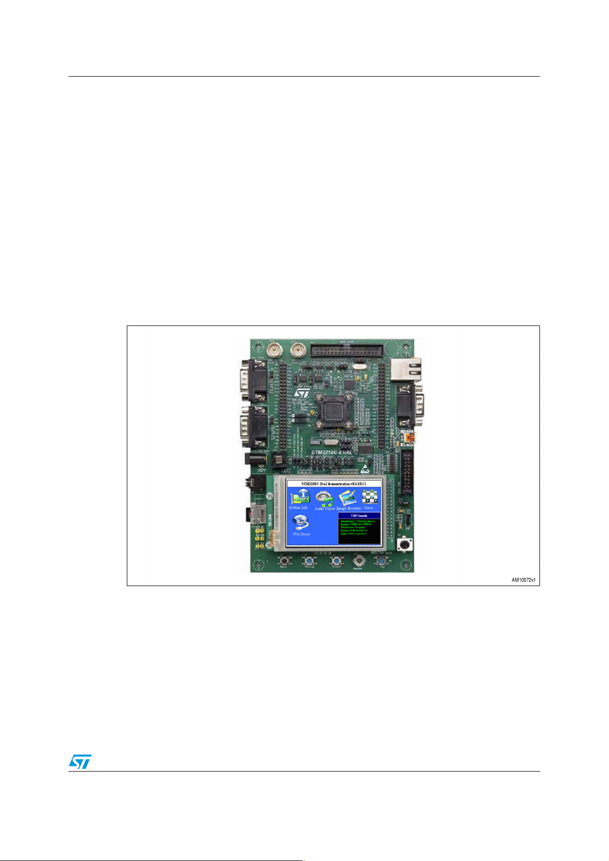
2.1 STM3210C-EVAL demonstration board
The STM3210C-EVAL is a standard evaluation tool for the STM32F107xx microcontroller
which includes an embedded Ethernet controller; this is the main feature necessary for the
home web console. For further details about this board please refer to the UM0600 user
manual.
Figure 1. STM3210C-EVAL demonstration board
The connectors CN8 and CN9, which include all the MCU pinouts, are used to connect the
SPZB260-PRO adapter, so a specific configuration of the board is necessary to free some
MCU I/O resources. The following is the board setup:
● To close jumper JP19
● To open jumper JP15
● To remove R79, R84 and R169.
Tab l e 2 shows the pinout mapping of the connectors over the adapter.
Doc ID 022161 Rev 1 5/21
Page 6
Hardware kit AN3972
Table 2. SPZB260-PRO adapter pin description
STM32 pin no. Pin name
- VDD 3.3 V CN8-Pin 48 VCC_3V3
- VSS GND CN9-Pin 50 GND
29 PA4 SPI1_NSS CN9-Pin 41 ZIG_SS
30 PA5 SPI1_CLK CN9-Pin 40 ZIG_SCLK
31 PA6 SPI1_MISO CN9-Pin 38 ZIG_MISO
32 PA7 SPI1_MOSI CN9-Pin 37 ZIG_MOSI
92 PB6 CAN2_TX/I2C1_SCK CN8-Pin 36 I2C1_SCK
93 PB7 I2C1_SDA CN8-Pin 37 I2C1_SDA
2 PE3 Trace_D0 CN8-Pin 42 ZIG_HOST_INT
3 PE4 Trace_D1 CN8-Pin 43 VCC-GPIO (for M24LR64-r)
4 PE5 Trace_D2 CN8-Pin 44 ZIG_WAKE
5 PE6 Trace_D3 CN8-Pin 47 ZIG_RSTB
STM3210C-EVAL
I/O assignment
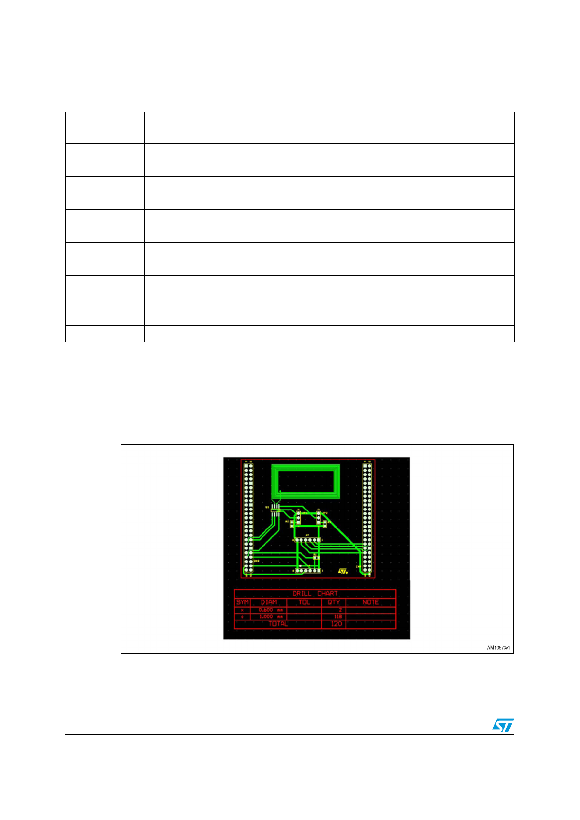
2.2 SPZB260-PRO adapter
This board allows to add the ZigBee connectivity to the STM3210C-EVAL board; it includes
the connectors for the SPZB260-PRO module and the M24LR64-R dual interface EEPROM.
Figure 2 shows the adapter layout.
Extension
connector pin no.
ZigBee adapter I/O
assignment
Figure 2. SPZB260-PRO adapter layout
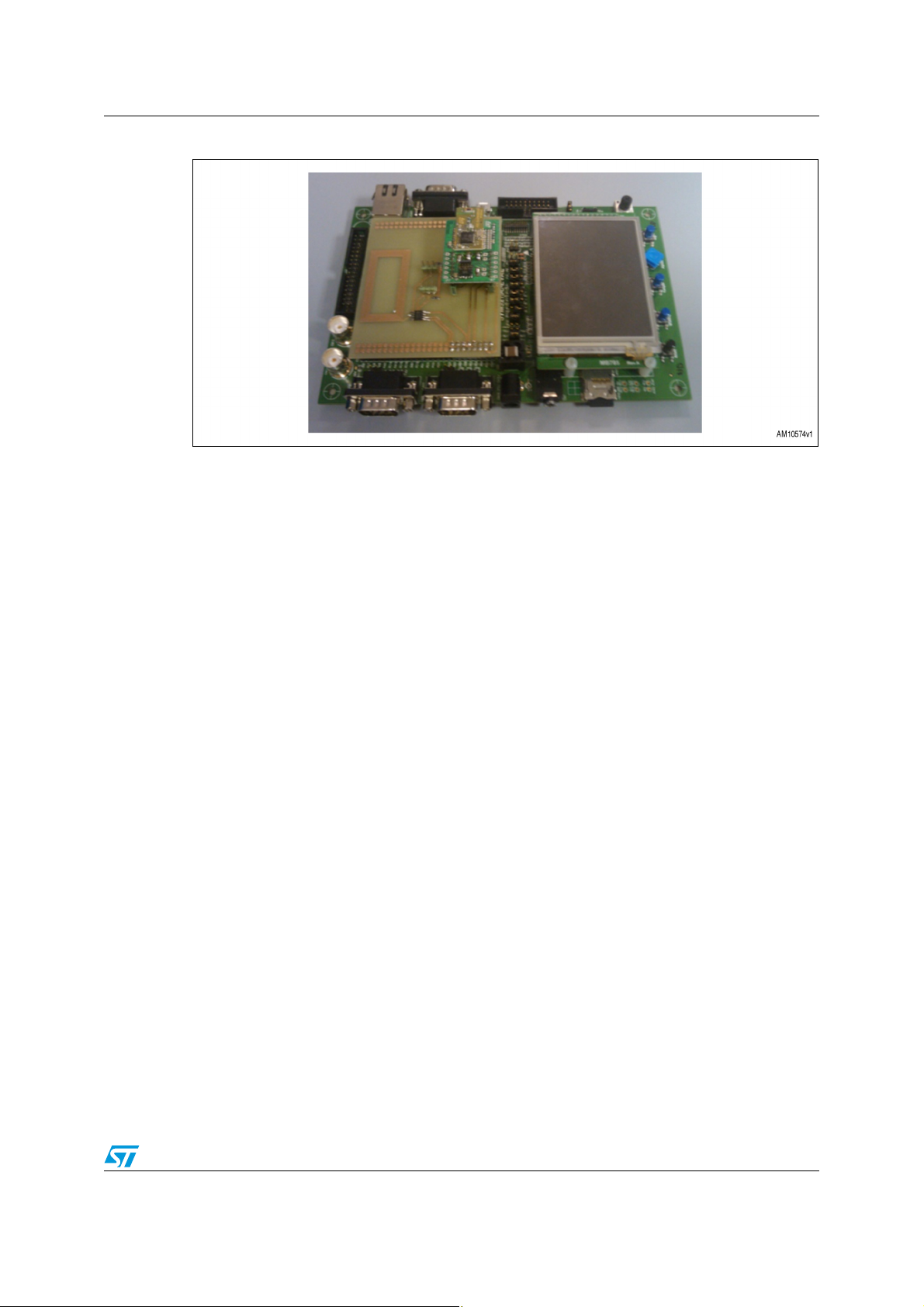
Figure 3 shows how to connect to the STM3210C-EVAL board.
6/21 Doc ID 022161 Rev 1
Page 7
AN3972 Hardware kit
Figure 3. How to connect SPZB260-PRO adapter to the STM3210C-EVAL
The SPZB260-PRO is a 2.4 GHz ZigBee module compliant with FCC regulations (FCC ID:
S9NZB260A); for further information refer to the SPZB260-PRO datasheet. The M24LR64R is an EEPROM with both I
access for an MCU using the I
2
C interface and RF interface; this allows a “standard” memory
2
C and an access for a standard long range (ISO 15693/ISO
18000-3 mode 1) RFID reader. Using the RF interface, the memory can read/write even
when it is not powered. In this application, the EEPROM stores, in the first three 32-bit
memory locations, the TCP/IP network parameters:
● IP address
● Gateway IP address
● IP address mask.
The parameters are programmed by the RFID reader with the board switched off and at the
power-on, during boot, the MCU reads the network parameters to configure the TCP/IP
stack. The 64-Kbit memory is organized into 8192 x 8 bits accessing from the I
into 2048 x 32 bits accessing from the RF interface. M24LR64-R is the slave of the I
2
C bus and
2
C
communication with STM32; the two jumpers included on the board are used to set the
slave address of the memory. For further information about M24LR64-R functionalities, refer
to the M24LR64-R datasheet; for information related to application development, several
application notes are available for downloading at www.st.com.
Doc ID 022161 Rev 1 7/21
Page 8

Hardware kit AN3972
2.3 STEVAL-IHP001V3
The STEVAL-IHP001V3 ZigBee smartplug demonstration board employs the STM32F10x
microcontroller, ZigBee SPZB260-PRO module, and STPM01 energy metering IC to
implement a ZigBee meter node which allows the user to monitor and manage the energy
consumption of a connected load.
In a typical home system implementation, the board is plugged into an electrical wall socket,
and supplies a home appliance or other generic electrical load. Current, power, energy and
other information related to the electrical load connected to the smartplug board can be
shown on an LCD displayed locally, or sent to a ZigBee data concentrator through a
home/building ZigBee network.
While the STEVAL-IHP001V3 replaces the STEVAL-IHP001V2, the hardware for both the
V2 and V3 versions of the smartplug demonstration boards are identical. The STEVALIHP001V3 differs from the V2 version only in terms of the ZigBee PRO stack update. More
information is available for downloading at www.st.com.
8/21 Doc ID 022161 Rev 1
Page 9

AN3972 Application firmware description
3 Application firmware description
The firmware has been developed over the FreeRTOS operating system in order to simplify
the integration of the different application parts. Figure 4 shows the firmware architecture.
Figure 4. Firmware architecture
The firmware includes a common hardware dependent layer which mainly includes the
STM32 standard library; over this layer the libraries and the application tasks are grouped in
two sections: one for the ZigBee part and the other for the TCP/IP part. The FreeRTOS
allows the correct execution of these tasks and their interaction.
3.1 ZigBee section
3.1.1 ZigBee libraries
The ZigBee libraries, which are independent from the OS, are part of the firmware package
of the STEVAL-IHP001V3 board and are fully documented; please refer to www.st.com.
3.1.2 ZigBee application layer
The application is based on the same principle as the typical “sink - sensors” scenario
supporting a “many-to-one” protocol, where there are several sensors (which in this case
are the smartplugs) that periodically send data to a concentrator, which in this case is also
the network coordinator, and is implemented by the STM3210C-EVAL.
The application layer is implemented by the task prvApplicationTask which is implemented
inside the “main.c” file. It calls the function emberTick, which includes the functions for the
ZigBee stack finite state machine evolution, and the function applicationTick, which
implements the ZigBee section of the application layer.
The application maintains a list of the smartplugs joined to the HAN; a smartplug is removed
from this list when it isn't heard from for a specified time and it is added when the
concentrator receive a “select-sink” message from it; this message is managed in
handleSensorSelectSink called by the callback function ezspIncomingMessageHandler. At
Doc ID 022161 Rev 1 9/21
Page 10

Application firmware description AN3972
the same time, the application periodically sends in broadcast the “Sink-Advertise” message
to keep the network alive and a “many-to-one-route-request” to update the routing tables of
all smartplugs in the network. The code sections that implement these functions are the
following:
Joined smartplugs list maintenance
for (i=0; i<APPLICATION_ADDRESS_TABLE_SIZE; i++) {
if (ticksSinceLastHeard[i] != 0xFFFF) {
if (++ticksSinceLastHeard[i] >
(MISS_PACKET_TOLERANCE * SEND_DATA_RATE)) {
//Remove the lost SmartPlug from the Plugs collection MP
CoordinatorType* pObjCoordinator = GetCoordinatorObj();
if(pObjCoordinator){
pObjSmartPlug = pObjCoordinator
>GetSmartPlug(pObjCoordinator,emberGetAddressTableRemoteNodeId(i));
if ( pObjSmartPlug )
{
id = pObjSmartPlug->ID;
pObjCoordinator>DelSmartPlug(pObjCoordinator,emberGetAddressTableRemoteNodeId(i));
sprintf( msg, "Node %d Deleted", id );
LCD_DisplayStringLineCol(Line8, 300, ( unsigned char * )msg );
emberSetAddressTableRemoteNodeId(i, EMBER_TABLE_ENTRY_UNUSED_NODE_ID);
emberSerialPrintf(APP_SERIAL,
"EVENT: too long since last heard, ");
emberSerialPrintf(APP_SERIAL,
"deleting address table index %x, status %x\r\n", i,
status);
ticksSinceLastHeard[i] = 0xFFFF;
}
}
}
}
}
Network maintenance
if (timeBeforeSinkAdvertise == 2) {
status = emberSendManyToOneRouteRequest(concentratorType,
10); // radius
emberSerialPrintf(APP_SERIAL,
"EVENT: sink send many-to-one route request,"
" status 0x%x\r\n", status);
}
10/21 Doc ID 022161 Rev 1
Page 11

AN3972 Application firmware description
// do the sink advertise (multicast)
if (timeBeforeSinkAdvertise == 0) {
emberSerialPrintf(APP_SERIAL,
"EVENT: sink automatically advertising to find sensors\r\n");
sinkAdvertise();
timeBeforeSinkAdvertise = TIME_BEFORE_SINK_ADVERTISE;
}
Each smartplug object of the list includes all the information related to the power
consumption measurement of each smartplug device installed in the building. These data
are sent using a private ZigBee profile with a specific cluster ID
(CLUST_GET_PLUG_DATA_ID = 0x1010) which is initialized into the function
ZB_ClustersInitialization; the message related to this cluster is managed by the function
OnGetPlugDataMsg that updates the data of the smartplug object included in the smartplug
objects list.
The smartplug devices are compliant with both the “Home Automation” profile and the
private profile implemented in the Home Web Console application running on the
STM3210C-EVAL. On the smartplug, the ON/OFF command is implemented by the HA
standard profile so the home web console uses a standard ZCL command for this command
implemented by the function SendZclOnOffCmd.
3.2 TCP/IP section
3.2.1 TCP/IP stack
The web section of the application is based on the “lwIP” stack implemented by SICS. It is
designed to reduce memory usage and code size in order to be used in embedded systems.
For details related to this TCP/IP stack, refer to the lwIP manual available at www.sics.se.
The TCP/IP task, which is implemented by the tcpip_thread function, is created by the
function vStartEthernetTasks. The tcpip_thread task creates the task ethernetif_input that
manages the messaging process with the Ethernet controller which is embedded in STM32.
3.2.2 TCP/IP application layer
The HTTP server services run on the task httpd; it mainly creates a TCP listener on port 80
and as soon as an incoming connection is received the server accepts it and parses the
HTML request by the function ParseHTMLRequest; after the parsing procedure the
connection is closed. The task is normally in sleep state and it is woken up by the incoming
connection request from the client.
The HTML parser processes both GET and POST requests and expects to immediately get
the data. The web page is made up of two static parts and two dynamic parts, so it is
organized into four frames. The static parts and the “index” pages are stored in the
embedded flash of the STM32; the dynamic parts are built at runtime on the basis of the
smartplug data objects list maintained by the ZigBee application layer described in
Section 3.1.2. The first dynamic part shows a table reporting the label, the measured
voltage, current and power consumption for each smartplug in the HAN; the table is
refreshed every 30 seconds. The second dynamic part shows a list of smartplugs (using the
Doc ID 022161 Rev 1 11/21
Page 12

Application firmware description AN3972
labels) according to the table allowing the selection of each smartplug and sends an ON or
OFF command to it. The command is sent as a POST request to the web server. The page
is formatted according to a styles file (.css) which is also stored in the embedded flash.
The network parameters (IP address, IP Gateway address, and IP address subnet mask)
are stored in the DUAL-EEPROM included in the ZigBee module adapter and read at the
startup by the MCU; if an EEPROM isn't recognized the default values are used. The
parsing procedure is as follows:
HTML parsing procedure
if( pxRxBuffer != NULL )
{
// Where is the data?
netbuf_data( pxRxBuffer, ( void * ) &pcRxString, &usLength );
// Is this a GET? We don't handle anything else.
if( !strncmp( pcRxString, "GET ", 4 ) )
{
for(int i = 4; i < usLength; i++)
{
if (pcRxString[i] == ' ' || pcRxString[i] == '\r' || pcRxString[i]
== '\n')
{
pcRxString[i] = 0;
}
}
// Is the page requested debug.html ?
if ( !strncmp((char *)pcRxString + 4, "/top3.htm", 9) )
{
++sReqCount;
// Build the dynamic page
file.data = s_cDynamicPage;
PrepareFrame2(s_cDynamicPage,pxNetCon);
file.len = strlen(s_cDynamicPage);
--sReqCount;
}
else if ( !strncmp((char *)pcRxString + 4, "/top2.htm", 9) )
{
// Build the dynamic page
file.data = s_cDynamicPage;
PrepareFrame1(s_cDynamicPage,pxNetCon);
file.len = strlen(s_cDynamicPage);
}
12/21 Doc ID 022161 Rev 1
Page 13

AN3972 Application firmware description
else if ( !strncmp((char *)pcRxString + 4, "/conf.htm", 9) )
{
// Build the dynamic page
file.data = s_cDynamicPage;
PrepareFrameConf(s_cDynamicPage,pxNetCon);
file.len = strlen(s_cDynamicPage);
}
else
{
int nFileFound = 0;
if (*(char *)(pcRxString + 4) == '/' && *(char *)(pcRxString + 5)
== 0)
{
if ( sReqCount < 1 )
nFileFound = fs_open("/index.html", &file);
else
nFileFound = 0;
}
else
{
nFileFound = fs_open((char *)pcRxString + 4, &file);
}
if (!nFileFound)
{
fs_open("/404.html", &file);
}
}
// Write out the HTTP OK header.
strcpy(txt, webHTTP_OK);
sprintf( txt + strlen(webHTTP_OK), webHTTP_Info, file.len );
// Write out the HTTP Info header.
netconn_write( pxNetCon, txt, (u16_t) strlen(txt), NETCONN_COPY );
// Write out the dynamically generated page.
WriteGeneratedPages(file,pxNetCon);
}
//Post Command Handler
if( !strncmp( pcRxString, "POST ", 5 ) )
{
if ( !strncmp((char *)pcRxString + 5, "/top2.htm", 9) )
{
Doc ID 022161 Rev 1 13/21
Page 14

Application firmware description AN3972
//Detect Smart Plug Action
ActionDetect(pcRxString, usLength ); //SB
PrepareFrame1(s_cDynamicPage,pxNetCon);
file.data = s_cDynamicPage;
file.len = strlen(s_cDynamicPage);
}
else if ( !strncmp((char *)pcRxString + 5, "/conf.htm", 9) )
{
//Detect Smart Plug Action
ActionDetectConf(pcRxString, usLength ); //SB
PrepareFrameConf(s_cDynamicPage,pxNetCon);
file.data = s_cDynamicPage;
file.len = strlen(s_cDynamicPage);
}
strcpy(txt, webHTTP_OK);
sprintf( txt + strlen(webHTTP_OK), webHTTP_Info, file.len );
// Write out the HTTP Info header.
netconn_write( pxNetCon, txt, (u16_t) strlen(txt), NETCONN_COPY );
WriteGeneratedPages(file,pxNetCon);
}
netbuf_delete( pxRxBuffer );
}
14/21 Doc ID 022161 Rev 1
Page 15
AN3972 Application firmware description
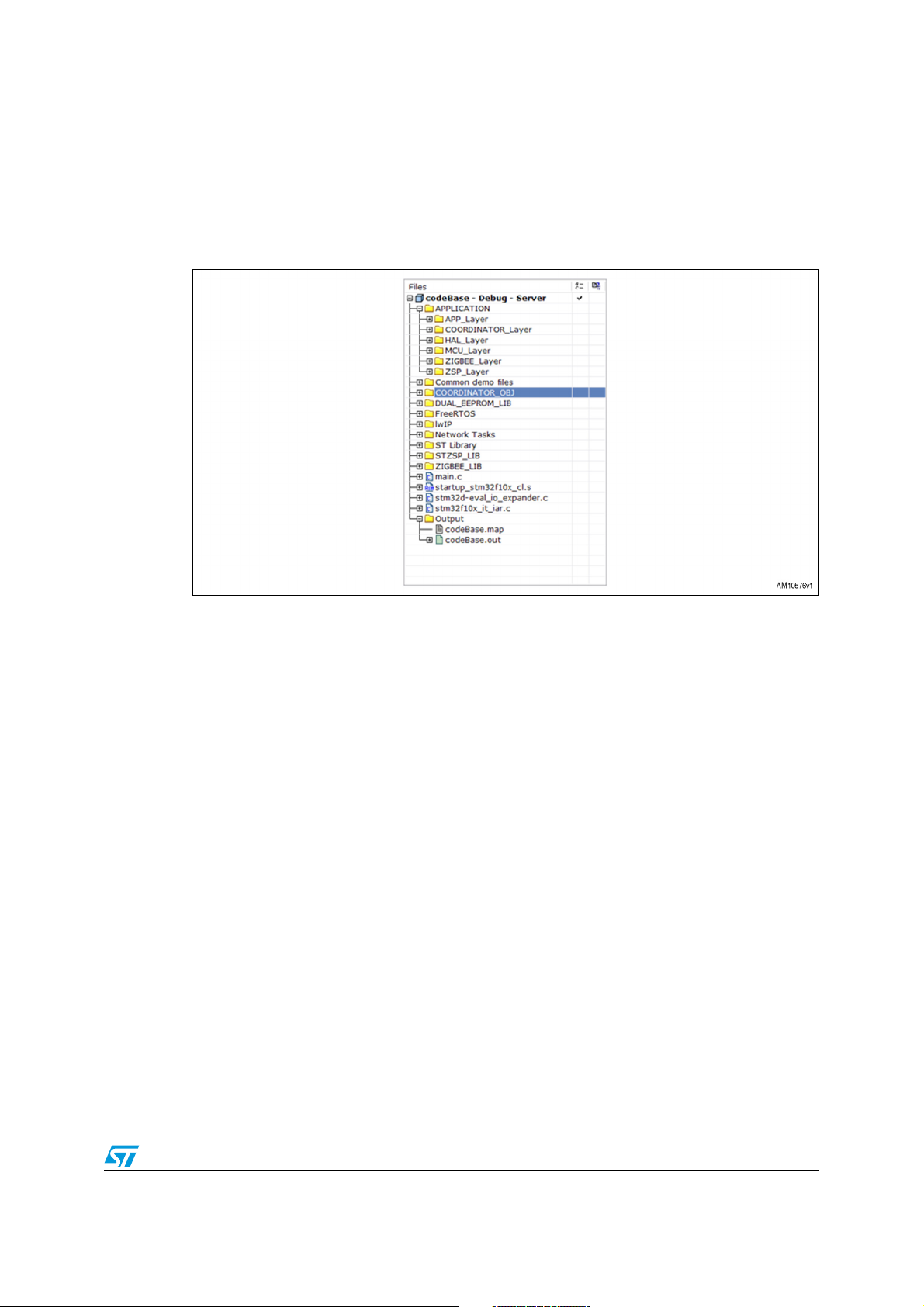
3.3 Source code organization
The firmware has been developed using IAR v5.50.1 but it is portable with minimum effort to
other development tools. The source code is organized following the folder tree shown in
Figure 5.
Figure 5. Source code folder tree
The “STZSP_LIB” folder files include all the low level functions for interfacing the SPZB260PRO module; the “ZIGBEE_LIB” and “COORDINATOR_OBJ” folders include the basic
ZigBee libraries which implement the ZigBee data, the smartplug data and Coordinator data
objects. The “APPLICATION” folder files include the interface to the ZigBee basic libraries
and also the application layer source files.
The “DUAL_EEPROM_LIB” folder includes the library for the I
The “FreeRTOS” includes all source file of the OS from www.freertos.org. The source code
reports the license agreement to use it.
The “lwIP” folder includes the source file of the TCP/IP stack from SICS. The source code
reports the license agreement to use it.
The “Network Tasks” folder includes the source code of the tasks related to the TCP/IP
stack execution and the HTTP web server task with the file system implementation as well.
The “ST Library” folder includes the STM32 MCU standard library source files.
The “main.c” files include the configuration functions, the OS startup function, and the
ZigBee Section task prvApplicationTask.
2
C access of the M24LR64-R.
Doc ID 022161 Rev 1 15/21
Page 16
Demo setup AN3972
4 Demo setup
To set up the demo, one STM3210C-EVAL board (modified as described in Section 2.1) with
a ZigBee adapter is necessary, a set of STEVAL-IHP001V3s, a PC with Ethernet
connectivity, and an Ethernet switch (or hub) with standard Ethernet cable; if an Ethernet
switch (or hub) is not available it is possible to use a crossed Ethernet cable. The adapter is
not provided in the package but the Gerber files are available for downloading together with
the firmware package. By using the browser of the PC it is possible to monitor and control
each smartplug of the HAN simply writing the IP address of the board (shown in the board
display) in the address bar. It is possible to do the same from any computer connected to the
Internet configuring the PC as the Internet gateway, providing it has an Internet connection,
of course, with a public IP address; unfortunately, not all Internet providers assign public IP
by default.
Go step-by-step:
1. Turn on the STM3210C-EVAL board with daughterboard
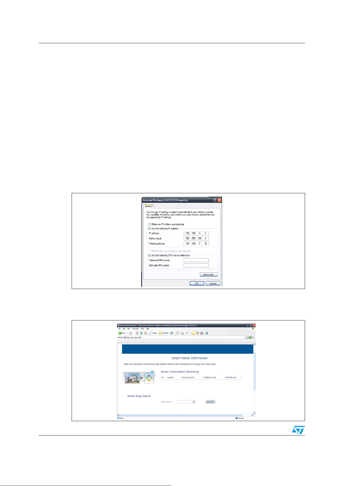
2. Set the PC network with static IP address
Figure 6. PC TCP/IP properties configuration
3. Connect the Ethernet cross-cable from STM3210C-EVAL to PC
4. Open Internet Explorer on 192.168.0.100 (as shown in the LCD display)
Figure 7. Smart Home Information web page
16/21 Doc ID 022161 Rev 1
Page 17
AN3972 Demo setup
5. Turn on one or more ZigBee smartplugs; make sure that the smartplug is linked to the
coordinator (STM3210C-EVAL board with daughterboard), in this case the connection
icon on the smartplug LCD should show the red light blinking; push the button on the
upper right on the smartplug to link/unlink to the coordinator.
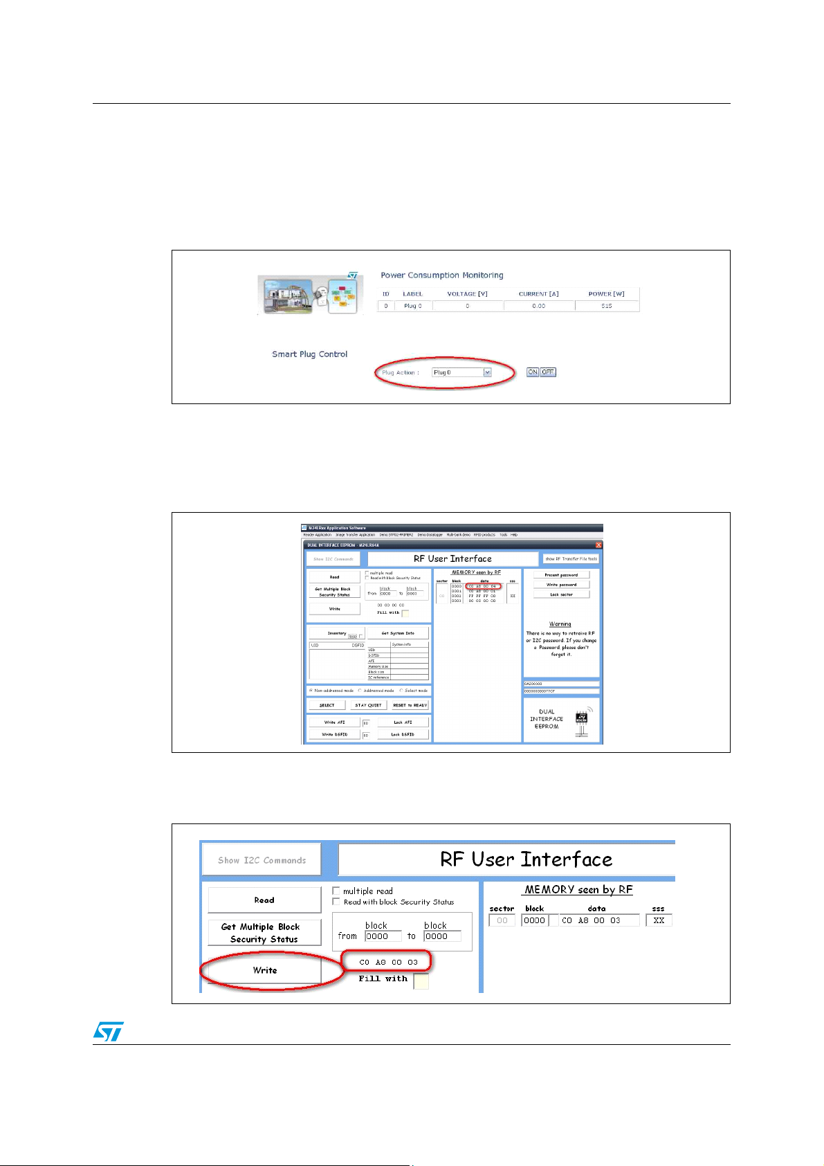
6. Refresh Internet Explorer
Figure 8. Smartplug list detail of Smart Home Information web page
7. Now it is possible to control the remote ZigBee smartplug
8. To change the IP address, the user must power off the board and connect to it using the
RF interface. For example, using STARTKIT M24LR64. In this case the user should
read the block 0 of the EEPROM DUAL IFs, 4 bytes, reading the actual IP address.
Figure 9. RFID PC user interface
9. The user can easily change this value, putting the new IP address in HEX, for example,
writing 192.168.0.3 --> C0h, A8,h 00h, 03h.
Figure 10. Writing details of RFID PC user interface
Doc ID 022161 Rev 1 17/21
Page 18
Demo setup AN3972
If it is available, the simplest method to use the PC as gateway is to share the Internet
connection and enable the web server service from the settings specifying the board IP
address. If the PC is configured correctly it works as a gateway with IP address 192.168.0.1;
the subnet mask of the LAN is set accordingly and if the board has, for example, an IP
address like 192.168.0.xxx, the subnet mask is set to 255.255.255.0, so it is enough to
configure the IP addresses set of the board accordingly; from a PC connected to the
Internet write the public IP address of the PC in the address bar to reach the web server
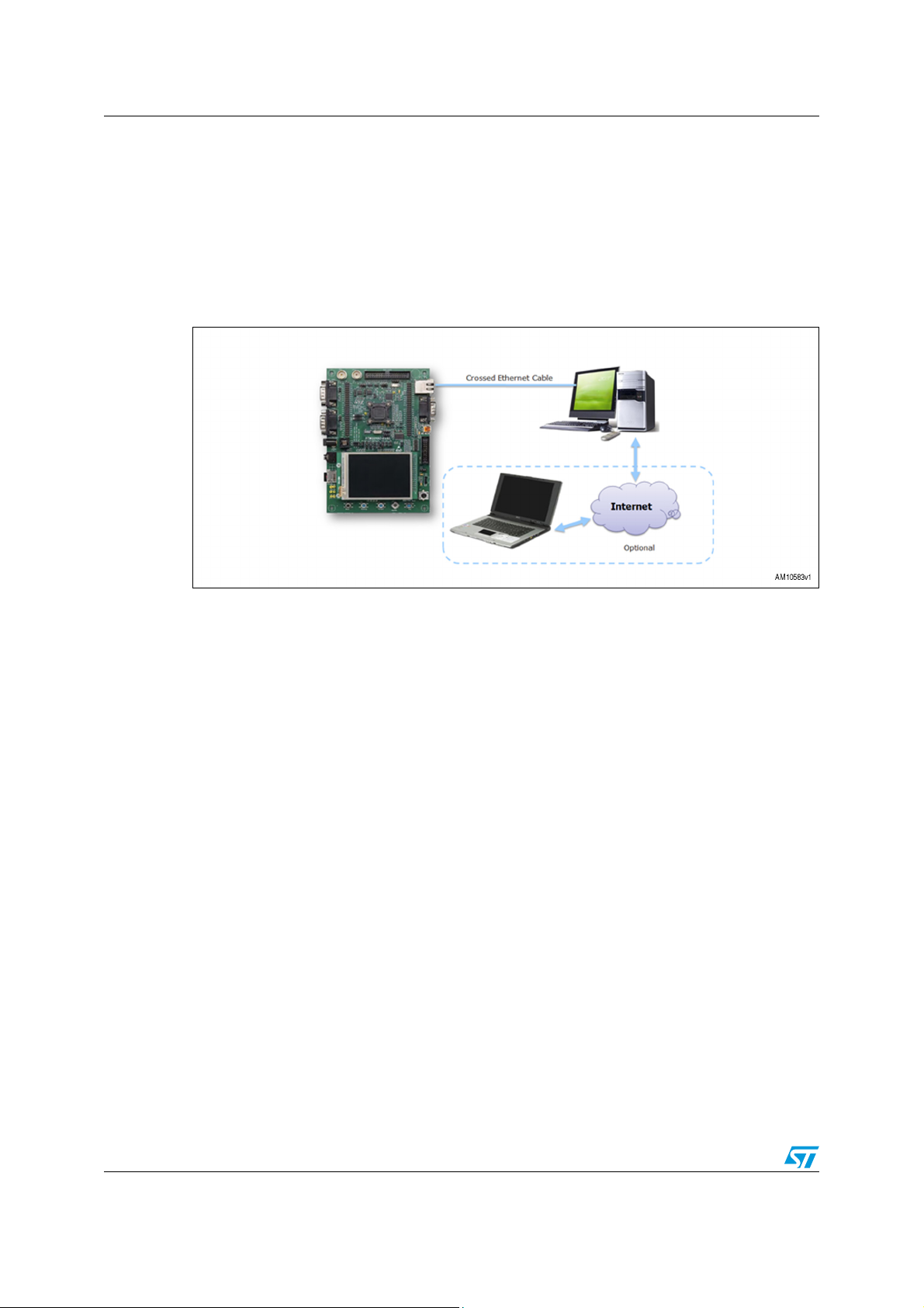
running on the STM3210C-EVAL board. Figure 11 shows a typical demo setup.
Figure 11. Demo setup
4.1 HTTP server limitations
The system has been tested with several Internet browsers and some limitation has been
found with the following browsers:
● Opera
● Mozilla
● Safari
The limitations are related mainly to the page formatting and, in the case of Safari, to the
POST management as well.
Full compatibility is only achieved with Internet Explorer and Google Chrome.
4.2 Demo limitations
Only for demonstration purposes, the number of smartplugs that the STM3210C-EVAL can
manage is limited to 5.
18/21 Doc ID 022161 Rev 1
Page 19

AN3972 References
5 References
1. STM32F107VC datasheet
2. RM0008 reference manual
3. STM32F10xFWLib 3.1.2
4. FreeRTOS official website www.freertos.org
5. lwIP user manual
6. SICS website www.sics.se
7. UM0600 user manual
8. AN2993 application note
Doc ID 022161 Rev 1 19/21
Page 20
Revision history AN3972
6 Revision history
Table 3. Document revision history
Date Revision Changes
11-Nov-2011 1 Initial release.
20/21 Doc ID 022161 Rev 1
Page 21

AN3972
Please Read Carefully:
Information in this document is provided solely in connection with ST products. STMicroelectronics NV and its subsidiaries (“ST”) reserve the
right to make changes, corrections, modifications or improvements, to this document, and the products and services described herein at any
time, without notice.
All ST products are sold pursuant to ST’s terms and conditions of sale.
Purchasers are solely responsible for the choice, selection and use of the ST products and services described herein, and ST assumes no
liability whatsoever relating to the choice, selection or use of the ST products and services described herein.
No license, express or implied, by estoppel or otherwise, to any intellectual property rights is granted under this document. If any part of this
document refers to any third party products or services it shall not be deemed a license grant by ST for the use of such third party products
or services, or any intellectual property contained therein or considered as a warranty covering the use in any manner whatsoever of such
third party products or services or any intellectual property contained therein.
UNLESS OTHERWISE SET FORTH IN ST’S TERMS AND CONDITIONS OF SALE ST DISCLAIMS ANY EXPRESS OR IMPLIED
WARRANTY WITH RESPECT TO THE USE AND/OR SALE OF ST PRODUCTS INCLUDING WITHOUT LIMITATION IMPLIED
WARRANTIES OF MERCHANTABILITY, FITNESS FOR A PARTICULAR PURPOSE (AND THEIR EQUIVALENTS UNDER THE LAWS
OF ANY JURISDICTION), OR INFRINGEMENT OF ANY PATENT, COPYRIGHT OR OTHER INTELLECTUAL PROPERTY RIGHT.
UNLESS EXPRESSLY APPROVED IN WRITING BY TWO AUTHORIZED ST REPRESENTATIVES, ST PRODUCTS ARE NOT
RECOMMENDED, AUTHORIZED OR WARRANTED FOR USE IN MILITARY, AIR CRAFT, SPACE, LIFE SAVING, OR LIFE SUSTAINING
APPLICATIONS, NOR IN PRODUCTS OR SYSTEMS WHERE FAILURE OR MALFUNCTION MAY RESULT IN PERSONAL INJURY,
DEATH, OR SEVERE PROPERTY OR ENVIRONMENTAL DAMAGE. ST PRODUCTS WHICH ARE NOT SPECIFIED AS "AUTOMOTIVE
GRADE" MAY ONLY BE USED IN AUTOMOTIVE APPLICATIONS AT USER’S OWN RISK.
Resale of ST products with provisions different from the statements and/or technical features set forth in this document shall immediately void
any warranty granted by ST for the ST product or service described herein and shall not create or extend in any manner whatsoever, any
liability of ST.
ST and the ST logo are trademarks or registered trademarks of ST in various countries.
Information in this document supersedes and replaces all information previously supplied.
The ST logo is a registered trademark of STMicroelectronics. All other names are the property of their respective owners.
© 2011 STMicroelectronics - All rights reserved
STMicroelectronics group of companies
Australia - Belgium - Brazil - Canada - China - Czech Republic - Finland - France - Germany - Hong Kong - India - Israel - Italy - Japan -
Malaysia - Malta - Morocco - Philippines - Singapore - Spain - Sweden - Switzerland - United Kingdom - United States of America
www.st.com
Doc ID 022161 Rev 1 21/21
 Loading...