

Page 1

AN3433
Application note
Optimizing wakeup time and power consumption
in CR95HF and STRFNFCA devices
Introduction
This document describes several tips for application engineers to effectively manage CR95HF and
STRFNFCA operating states and modes to define an adapted wakeup condition to return to its Active
state to start communication with the external world in order to reduce power consumption.
The CR95HF and STRFNFCA have 2 main functional domains. In the first one, Active mode, the devices
are able to communicate with a host using one of the serial interfaces (UART or SPI) or with RFID tags
using its RF capabilities. In this mode, the device consumption is only a few milliamps, and when it emits
RF signals, its field consumption becomes tens of milliamps. In the second domain, Wait for Event (WFE)
mode, the device remains quiescent while waiting for an external event. In this mode, a very low level of
power consumption (only a few microamps) may be achieved.
An application engineer is able to manage the wakeup conditions in order to adapt his strategy to
optimize wakeup time or system power consumption.
This application note will provide guidelines for choosing the best implementation.
February 2012 Doc ID 019046 Rev 2 1/34
www.st.com
Page 2

Contents AN3433
Contents
Introduction . . . . . . . . . . . . . . . . . . . . . . . . . . . . . . . . . . . . . . . . . . . . . . . . . . . . . . . . . 1
1 Reference information . . . . . . . . . . . . . . . . . . . . . . . . . . . . . . . . . . . . . . . 4
1.1 Reference documents . . . . . . . . . . . . . . . . . . . . . . . . . . . . . . . . . . . . . . . . 4
1.2 Terms and acronyms . . . . . . . . . . . . . . . . . . . . . . . . . . . . . . . . . . . . . . . . . 4
1.3 Notation conventions . . . . . . . . . . . . . . . . . . . . . . . . . . . . . . . . . . . . . . . . . 4
2 Management of CR95HF or STRFNFCA activity . . . . . . . . . . . . . . . . . . . 6
2.1 Overview of operating modes . . . . . . . . . . . . . . . . . . . . . . . . . . . . . . . . . . . 6
2.2 Idle command . . . . . . . . . . . . . . . . . . . . . . . . . . . . . . . . . . . . . . . . . . . . . . . 7
2.3 Idle command parameters . . . . . . . . . . . . . . . . . . . . . . . . . . . . . . . . . . . . . 9
2.4 Using LFO frequency setting to reduce power consumption . . . . . . . . . . 10
2.5 Optimizing wake-up conditions . . . . . . . . . . . . . . . . . . . . . . . . . . . . . . . . . 11
2.5.1 Wake-up source register . . . . . . . . . . . . . . . . . . . . . . . . . . . . . . . . . . . . 11
2.6 Using various techniques to return to Ready state . . . . . . . . . . . . . . . . . 12
2.6.1 Default setting: from POR to Ready state . . . . . . . . . . . . . . . . . . . . . . . 12
2.6.2 From Ready state to Hibernate state and back to Ready state . . . . . . . 12
2.6.3 From Ready state to Sleep state and back to Ready state . . . . . . . . . . 12
2.7 Tag detection calibration procedure . . . . . . . . . . . . . . . . . . . . . . . . . . . . . 14
3 Power consumption considerations . . . . . . . . . . . . . . . . . . . . . . . . . . . 16
3.1 Transition from Ready to Hibernate state . . . . . . . . . . . . . . . . . . . . . . . . . 16
3.2 Transition from Ready to Sleep state . . . . . . . . . . . . . . . . . . . . . . . . . . . . 18
3.3 Wake-up by Tag Detection . . . . . . . . . . . . . . . . . . . . . . . . . . . . . . . . . . . . 18
Appendix A Tag detection principle . . . . . . . . . . . . . . . . . . . . . . . . . . . . . . . . . . . 22
A.1 Tag detection sequence . . . . . . . . . . . . . . . . . . . . . . . . . . . . . . . . . . . . . . 23
Appendix B Tag Detection Calibration process. . . . . . . . . . . . . . . . . . . . . . . . . . 26
B.1 Tag Detection Calibration algorithm . . . . . . . . . . . . . . . . . . . . . . . . . . . . . 26
B.2 Tag Detection calibration command . . . . . . . . . . . . . . . . . . . . . . . . . . . . . 27
Appendix C Example of CR95HF tag detection calibration process . . . . . . . . . 29
2/34 Doc ID 019046 Rev 2
Page 3

AN3433 Contents
Appendix D Example of CR95HF tag detection command using results of tag
detection calibration . . . . . . . . . . . . . . . . . . . . . . . . . . . . . . . . . . . . . 32
Revision history . . . . . . . . . . . . . . . . . . . . . . . . . . . . . . . . . . . . . . . . . . . . . . . . . . . . 33
Doc ID 019046 Rev 2 3/34
Page 4

Reference information AN3433
1 Reference information
1.1 Reference documents
CR95HF: 13.56 MHz Multi-protocol Contactless Transceiver IC with SPI and UART serial
access datasheet
STRFNFCA: Near field communication transceiver datasheet
1.2 Terms and acronyms
Table 1. List of terms and acronyms
Term Meaning
AFE Analog Front End
DAC Digital-to-analog converter
DFT Design for Test
NVM Non Volatile Memory
RFID Radio frequency identification
RFU Reserved for Future Use
WFE Wait For Event
1.3 Notation conventions
The following symbols correspond to:
>>>: Frame sent by the host to CR95HF or STRFNFCA
<<<: Frame sent by the CR95HF or STRFNFCA to the host
Table 2. List of characteristic values
Symbol Definition Value
CalRef
DacDataH High Level detection limit
DacDataL Low Level detection limit
MaxSleep Number of inactivity periods (t
SwingCnt Number of 13.56 MHz periods in the RF burst
t
DAC
t
HFO
t
INACTIVE
t
LFO
Tag Calibration Reference level and
DAC threshold level for device setup
DAC set up time
Period of RF carrier (13.56 MHz) 73 ns
Inactivity period, delay between two wakeups for RF burst
emissions in a Tag Detection sequence
Period of device Low frequency oscillator (32 kHz) 31.25 µs
INACTIVE
) before a timeout.
t
INACTIVE
(WuPeriod+1)*t
=
REF
4/34 Doc ID 019046 Rev 2
Page 5

AN3433 Reference information
Table 2. List of characteristic values (continued)
Symbol Definition Value
t
OSC
t
REF
t
SWING
t
TO
WuPeriod
Oscillator set-up time
Reference time
RF Burst duration in Tag detection t
Timeout delay after which the device will automatically
leave WFE mode.
Number of reference times (RT) in an inactivity period
(t
INACTIVE
)
t
REF
= 256*t
SWING
t
TO
t
INACTIVE
= 8 ms
LFO
= Swing * t
= (MaxSleep) *
HFO
Doc ID 019046 Rev 2 5/34
Page 6
Management of CR95HF or STRFNFCA activity AN3433
2 Management of CR95HF or STRFNFCA activity
2.1 Overview of operating modes
The CR95HF and STRFNFCA have 2 operating modes: Wait for Event (WFE) and Active. In
Active mode, the device communicates actively with a tag or an external host (MCU). WFE
mode includes four low consumption states: Power-up, Hibernate, Sleep and Tag Detector.
The CR95HF or STRFNFCA can switch from one mode to another.
Table 3. CR95HF or STRFNFCA operating modes and states
Mode State Description
This mode is accessible directly after POR.
Wait For
Event
(WFE)
Active
Power-up
Hibernate
Sleep
Tag D e t e c t o r
Power-up
Hibernate
Low level on IRQ_IN
source. LFO (low-frequency oscillator) is running in this state.
Lowest power consumption state. The device has to be woken-up in
order to communicate. Low level on IRQ_IN pin (longer than 10 µs) is
the only wakeup source.
Low power consumption state. Wakeup source is configurable:
–Timer
–IRQ_IN
– SPI_SS pin
LFO (low-frequency oscillator) is running in this state.
Low power consumption state with tag detection. Wakeup source is
configurable:
–Timer
–IRQ_IN
– SPI_SS
– Tag detector
LFO (low-frequency oscillator) is running in this state.
This mode is accessible directly after POR.
Low level on IRQ_IN
source. LFO (low-frequency oscillator) is running in this state.
Lowest power consumption state. The device has to be woken-up in
order to communicate. Low level on IRQ_IN
the only wakeup source.
pin
pin
pin
pin (longer than 10 µs) is the only wakeup
pin (longer than 10 µs) is the only wakeup
pin (longer than 10 µs) is
Hibernate, Sleep and Tag Detector states can only be activated by a command from the
external host (MCU). As soon as any of these three states are activated, the device can no
longer communicate with the external host. It can only be woken up.
The behavior of the device in 'Tag Detector' state is defined by the Idle command.
6/34 Doc ID 019046 Rev 2
Page 7
AN3433 Management of CR95HF or STRFNFCA activity
Figure 1. CR95HF or STRFNFCA initialization and operating state change
2.2 Idle command
The Idle command switches the device into WFE mode (low consumption) and defines the
way it returns to Ready state.
In WFE mode, the device has two low consumption states: Hibernate and Sleep/TagDetector.
In Hibernate state, the device power consumption is extremely low (a few microamps)
because most of its resources are switched off. When it receives an external event (pin
IRQ_IN
In Sleep/Tag-Detector state, the device power consumption is low (tens of microamps)
depending on the selected wakeup source. The wakeup source can be an internal timer, an
external interrupt or the presence of a tag detected by the device.
In Tag-Detector state, after executing an initial Tag Detection Calibration procedure to set-up
the device, the application engineer must adjust command parameters to select the best
trade-off between the wakeup delay and the power budget.
), it will return to Ready mode in only a few milliseconds.
Doc ID 019046 Rev 2 7/34
Page 8
Management of CR95HF or STRFNFCA activity AN3433
Table 4. Idle command description
Direction Data Comments Example
07 Command code Example of switch from Active
mode to Hibernate state:
>>>0x07 0E 08 04 00 04
00 18 00 00 00 00 00 00
00 00
Example of switch from Active
to WFE mode (wakeup by low
pulse on IRQ_IN
>>>0x07 0E 08 01 00 38
00 18 00 00 00 00 00 00
00 00
Example of switch from Active
to WFE mode (wakeup by low
pulse on SPI_SS
>>>0x07 0E 10 01 00 38
00 18 00 00 00 00 00 00
00 00
Example of wakeup by timeout
L
(7 seconds):
Duration before Timeout = 256
* (WU period + 2) *
* t
L
(MaxSleep + 1)
L
>>>0x07 0E 01 21 00 38
00 18 00 60 60 00 00 00
00 08
Example of switch from Active
to Tag Detector mode (wakeup
by tag detection or low pulse
on IRQ_IN
pin) (32 kHz,
inactivity duration = 272 ms,
DAC oscillator = 3 ms, Swing
= 63 pulses of 13.56 MHz), 0A
= Infinite sequence, 0B = Until
TimeOut:
>>>0x07 0E 0A 21 00 79
01 18 00 20 60 60 64 74
3F 08
Example of a basic Idle
command used during the Tag
Detection Calibration process:
>>>0x07 0E 03 A1 00 F8
01 18 00 20 60 60 00 xx
3F 01
where xx is the DacDataH
value.
pin):
pin):
Host to
CR95HF or
STRFNFCA
0E Length of data
<WU Source>
EnterCtrlL
EnterCtrlH
WUCtrlL
WUCtrlH
LeaveCtrlL
LeaveCtrlH
Specifies authorized wakeup
sources and the LFO frequency
Settings to enter WFE mode
Settings to wake up from WFE
mode
Settings to leave WFE mode
(Default value = 0x1800)
Period of time between two tag
<WUPeriod>
detection bursts. Also used to
specify the duration before
timeout.
Defines the Wait time for HFO to
<OscStart>
stabilize: <OscStart> * t
(Default value = 0x60)
Defines the Wait time for DAC to
<DacStart>
stabilize: <DacStart> * t
(Default value = 0x60)
<DacDataL>
Lower compare value for tag
detection
This value must be set to 0x00
(1)
.
during Tag Detection
Calibration.
<DacDataH>
Higher compare value for tag
detection
This is a variable used during
(1)
.
Tag Detection Calibration.
<SwingsCnt>
Number of swings HF during tag
detection (Default value = 0x3F)
Max. number of tag detection
trials before timeout
This value must be set to 0x01
during Tag Detection
<MaxSleep>
Calibration.
Also used to specify duration
before timeout.
MaxSleep must be:
0x00 < MaxSleep < 0x1F
(1)
.
8/34 Doc ID 019046 Rev 2
Page 9
AN3433 Management of CR95HF or STRFNFCA activity
Table 4. Idle command description (continued)
Direction Data Comments Example
0x00 Result code This response is sent only
when CR95HF or STRFNFCA
exits WFE mode.
<<<0x000101 Wakeup by
timeout
<<<0x000102 Wakeup by
tag detect
CR95HF or
STRFNFCA
to Host
0x01 Length of data
<Data> Data (Wakeup source)
<<<0x000108 Wakeup by
low pulse on IRQ_IN
CR95HF or
STRFNFCA
to Host
1. An initial calibration is necessary to determine DacDataL and DacDataH values required for leaving Tag
Detector state. For more information, contact your ST sales office for the corresponding application note.
0x82 Error code
0x00 Length of data
<<<0x8200 Invalid command
length
pin
2.3 Idle command parameters
The Idle command (Host to device) has the following structure (all values are hexadecimal):
Table 5. Idle command structure
07 0E xx yy zz yy zz yy zz aa bb cc dd ee ff gg
Comma
nd code
Data
length
WU
source
Enter
Control
WU
Control
Leave
Control
WU
Period
Osc
Start
DAC
Start
DAC
Data
Swing
Count
Max
Sleep
Table 6. Summary of parameters
Parameter Description
Command code
Data length
This byte is the command code. ‘07’ represents the Idle command. This
command switches the device from Active mode to WFE mode.
This byte is the length of the command in bytes. Its value depends on the
following parameter values.
This byte defines the authorized wakeup sources in the wakeup source
WU Source
register. Predefined values are:
01: Time out 02: Tag Detection
08: Low pulse on IRQ_IN
These two bytes (EnterCtrlL and EnterCtrlH) define the resources when
entering WFE mode.
Enter Control
0x0400: Hibernate
0x0100: Sleep (or 0x2100 if Timer source is enabled)
0xA100: Tag Detector Calibration
0x2100: Tag detection
These two bytes (WuCtrlL and WuCtrlH) define the wakeup resources.
WU Control
0x0400: Hibernate 0x3800: Sleep
0xF801: Tag Detector Calibration 0x7901: Tag detection
10: Low pulse on SPI_SS
Doc ID 019046 Rev 2 9/34
Page 10

Management of CR95HF or STRFNFCA activity AN3433
Table 6. Summary of parameters (continued)
Parameter Description
These two bytes (LeaveCtrlL and LeaveCtrlH) define the resources when
Leave Control
WU Period
Osc Start
DAC Start
DAC Data
returning to Ready state.
0x1800: Hibernate 0x1800: Sleep
0x1800: Tag Detector Calibration 0x1800: Tag detection
This byte is the coefficient used to adjust the time allowed between two tag
detections. Also used to specify the duration before timeout. (Typical value:
0x20)
Duration before Timeout = 256 * tL * (WU period + 2) * (MaxSleep + 1)
This byte defines the delay for HFO stabilization. (Recommended value:
0x60)
Defines the Wait time for HFO to stabilize: <OscStart> * t
This byte defines the delay for DAC stabilization. (Recommended value:
0x60)
Defines the Wait time for DAC to stabilize: <DacStart> * t
These two bytes (DacDataL and DacDataH) define the lower and higher
comparator values, respectively. These values are determined by a
calibration process.
When using the device demoboard, these values should be set to
approximately 0x64 and 0x74, respectively.
L
L
Swing Count
Max Sleep
This byte defines the number of HF swings allowed during Tag Detection.
(Recommended value: 0x3F)
This byte defines the maximum number of tag detection trials or the
coefficient to adjust the maximum inactivity duration before timeout.
MaxSleep must be: 0x00 < MaxSleep < 0x1F
This value must be set to 0x01 during the Tag Detection Calibration
process.
Also used to specify duration before timeout.
Duration before Timeout = 256 * t
(Typical value: 0x28)
* (WU period + 2) * (MaxSleep + 1)
L
2.4 Using LFO frequency setting to reduce power consumption
In WFE mode, the high frequency oscillator (HFO) is stopped and most processes being
executed are clocked by the low frequency oscillator (LFO). To minimize CR95HF or
STRFNFCA power consumption in WFE mode, the slower the LFO frequency, the lower the
power consumption.
Example 1: Setting a lower LFO frequency
The following equation defines a basic timing reference:
t
= 256*tL ms (where tL = 1/f
REF
t
= 8 ms (when bits [7:6] are set to ‘00’, or 32 kHz)
REF
t
= 64 ms (when bits [7:6] are set to ‘11’, or 4 kHz)
REF
LFO
)
10/34 Doc ID 019046 Rev 2
Page 11

AN3433 Management of CR95HF or STRFNFCA activity
2.5 Optimizing wakeup conditions
Using the Wakeup source register, it is possible to cumulate sources for a wakeup event. It
is strongly recommended to always set an external event as a possible wakeup source.
To cumulate wakeup sources, simply set the corresponding bits in the wakeup source
register. For example, to enable a wakeup when a tag is detected (bit 1 set to ‘1’) or on a low
pulse on pin IRQ_IN
2.5.1 Wakeup source register
Wakeup conditions are defined in the 8-bit wakeup condition register. These bits select one
or several external conditions to be evaluated by the device in order to exit Idle mode.
Bit 0: When set, the device will wake up and return to Ready state at the end of a predefined
cycle. The Time Out (TO) value is defined by the Max sleep and Wake Up period:
TO = (MaxSleep *(WuPeriod+1)*RT or RT= 256*t
This bit must be set when using the timer as a possible wakeup source. It must be set during
Tag Detection Calibration to force a wakeup after the first Tag Detection trial.
Bit 1: When set, the device will wake up when a Tag is detected in the RF field. This bit must
also be set during Tag Detection Calibration or during Tag Detection (when the RF field is
active).
(bit 3 set to ‘1’), set the register to 0x0A.
= 8 ms
LFO
Bit 2: This bit is RFU.
Bit 3: When set, the device will wake up when an external interrupt (low level on pin IRQ_IN
is detected. This is useful for SPI communications.
It is recommended to set this bit to ‘1’ in order to recover in the event of a system crash.
Bit 4: When set, the device will wake up when an external interrupt (low level on pin
|SPI_SS
Bits [7:5] These bits are RFU.
) is detected. This is useful for UART communication.
Cumulation of wakeup conditions
The wakeup conditions selected in the Wakeup condition register can be cumulated.
When the device returns to Ready state, it is possible to use the RdReg command to read
the Wakeup condition register to know which event caused the device to wake up from Idle
mode.
Read Wakeup condition register: 08 03 62 01 00
Reply (‘xx’ represent the Wakeup condition register bits): 00 01 xx
This information is used after each iteration during the Tag Detection Calibration process to
determine the CalRef level. This level corresponds to the switching of the bits in the Wakeup
condition register from 0x02 (Tag Detector) to 0x01 (TimeOut) when using the device
previously calibrated in a free-air environment (no tags present).
)
Doc ID 019046 Rev 2 11/34
Page 12

Management of CR95HF or STRFNFCA activity AN3433
2.6 Using various techniques to return to Ready state
The Idle command and reply set offers several benefits to users by enabling various
methods to return the CR95HF or STRFNFCA to Ready state. Some methods are nearly
automatic, such as waiting for a timer overflow or a tag detection, but others consume more
power compared to the ones requesting a host action. A description of each method follows
below.
2.6.1 Default setting: from POR to Ready state
After power-on, the CR95HF or STRFNFCA enters Power-up state.
To wake up the device and set it to Ready state, the user must send a low pulse on the
IRQ_IN
enters Ready state and is able to accept commands after a delay of approximately 3 ms.
2.6.2 From Ready state to Hibernate state and back to Ready state
In Hibernate state, most resources are switched off to achieve an ultra-low power
consumption.
The only way the CR95HF or STRFNFCA can wake up from Hibernate state is by an
external event (low pulse on pin IRQ_IN
pin. The device then automatically selects the external interface (SPI or UART) and
).
A basic Idle command is:
>>>0x07 0E 08 04 00 04 00 18 00 00 00 00 00 00 00 00
Note: The Wakeup flag value is NOT significant when returning to Ready state from Hibernate
state or after a POR.
2.6.3 From Ready state to Sleep state and back to Ready state
Wake up by external event (low pulse on IRQ_IN or SPI_SS pin)
In Sleep or Power-up states, operating resources are limited in function of the selected
wakeup source to achieve a moderate power consumption level.
An Idle command example when wakeup source is pin IRQ_IN
>>>0x07 0E 08 01 00 38 00 18 00 00 60 00 00 00 00 00
A similar command can be implemented using pin SPI_SS
>>>0x07 0E 10 01 00 38 00 18 00 00 60 00 00 00 00 00
Wakeup by Timeout
The LFO is required to use the timer. However, this increases the typical power consumption
by 80 µA. Several parameters can be modified to reduce power consumption as much as
possible.
The Duration before Timeout is defined by parameters WU period and MaxSleep,
respectively 0x60 and 0x08 in the following example.
:
as a wakeup source:
Duration before Timeout = 256 * t
Note: Note that: 0x00 < MaxSleep < 0x1F.
12/34 Doc ID 019046 Rev 2
* (WU period + 2) * (MaxSleep + 1)
L
Page 13

AN3433 Management of CR95HF or STRFNFCA activity
An Idle command example when wakeup source is timer (0x01) when f
= 32 kHz (mean
LFO
power consumption is 25 µA)
>>>0x07 0E 01 21 00 38 00 18 00 60 60 00 00 00 00 08
An Idle command example when wakeup source is timer (0xC1) when f
= 4 kHz (mean
LFO
power consumption is 20 µA):
>>>0x07 0E C1 21 00 38 00 18 00 60 60 00 00 00 00 08
The same command can be used mixing a timer and the IRQ_IN
pin (0xC9) as a wakeup
source:
>>>0x07 0E C9 21 00 38 00 18 00 60 60 00 00 00 00 08
Wakeup by Tag Detection
In this mode, the typical consumption can greatly vary in function of parameter settings (WU
period without RF activity and Swing Count defining the RF burst duration). Using default
settings, consumption in the range of 100 µA can be achieved.
Tag Detector is a state where the CR95HF or STRFNFCA is able to detect an RF event and
a wakeup will occur when a tag sufficiently modifies the antenna load and is detected by the
device.
An Idle command example when wakeup source is Tag Detection (0x02):
>>>0x07 0E 02 21 00 79 01 18 00 20 60 60 64 74 3F 08
The same command can be used mixing Tag Detection and the IRQ_IN
wakeup source:
>>>0x07 0E 0A 21 00 79 01 18 00 20 60 60 64 74 3F 08
pin (0x0A) as a
The tag detection sequence is defined by dedicated parameters:
● WU source (Byte 3)
– The Timeout bit (bit 0) must be set to ‘1’ in order to manage a certain number of
emitted bursts. Otherwise, bursts will be sent indefinitely until a stop event occurs
(for example, tag detection or a low pulse on pin IRQ_IN
).
– The Tag Detect bit (bit 1) must be set to ‘1’ to enable RF burst emissions.
– It is recommended to also set Bits 3 or 4 to ‘1’ to ensure that it is possible to leave
Tag Detect mode via an external event (for example, a low pulse on pin IRQ_IN
● WU period (Byte 10): Defines the period of inactivity (t
t
INACTIVE
●
OscStart, DacStart (Bytes 11 and 12): Define the set-up time of the HFO and Digital
= (WuPeriod + 2) * t
REF
INACTIVE
) between two RF bursts:
).
Analog Converter, respectively. In general, 3 ms is used both set-up times.
HFO | DAC set-up time = (OscStart | DacStart) * t
● DacDataL, DacDataH (Bytes 13 and 14): Reference level for Tag Detection (calculated
L
during the tag detection calibration process).
● SwingsCnt (Byte 15): Represents the number of 13.56-MHz swings allowed during a
Tag Detection burst. We recommend using 0x3F.
● MaxSleep (Byte 16): The CR95HF or STRFNFCA emits (MaxSleep +1) bursts before
leaving Tag Detection mode if bit 0 (Timer Out) of the WU source register is set to ‘1’.
Otherwise, when this bit is set to ‘0’, a burst is emitted indefinitely.
Doc ID 019046 Rev 2 13/34
Page 14

Management of CR95HF or STRFNFCA activity AN3433
Note: Bytes 4 to 9 should be used as shown in the examples in Section 2.3: Idle command
parameters.
Note that the MaxSleep value is coded on the 5 least significant bits, thus:
0x00 < MaxSleep < 0x1F.
All the previously described command parameters must be chosen accordingly for the initial
tag detection calibration when setting up the CR95HF or STRFNFCA.
Their value will impact tag detection efficiency and CR95HF or STRFNFCA power
consumption during Tag Detection periods.
2.7 Tag detection calibration procedure
The Idle command allows the use of a tag detection as a wakeup event. Certain parameters
of the Idle command are dedicated to setting the conditions of a tag detection sequence.
During the tag detection sequence, the CR95HF or STRFNFCA regularly emits RF bursts
and measures the current in the antenna driver I
When a tag enters the device antenna RF operating volume, it modifies the antenna loading
characteristics and induces a change in I
, and consequently, the DAC data register
DRIVE
reports a new value.
using the internal 6-bit DAC.
DRIVE
This value is then compared to the reference value established during the tag detection
calibration process. This enables the device to decide if a tag has entered or not its
operating volume.
The reference value (DacDataRef) is established during a tag detection calibration process
using the device application setting with no tag in its environment.
The calibration process consists in executing a tag detection sequence using a well-known
configuration, with no tag within the antenna RF operating volume, to determine a specific
reference value (DacDataRef) that will be reused by the host to define the tag detection
parameters (DacDataL and DacDataH).
During the calibration process, DacDataL is forced to 0x00 and the software successively
varies the DacDataH value from its maximum value (0xFE) to its minimum value (0x00). At
the end of the calibration process, DacDataRef will correspond to the value of DacDataH for
which the wakeup event switches from timeout (no tag in the RF field) to tag detected.
To avoid too much sensitivity of the tag detection process, we recommend using a guard
band. This value corresponds to 2 DAC steps (0x08).
Recommended guard band value:
DacDataL = DacDataRef – Guard and DacDataH = DacDataRef + Guard
The parameters used to define the tag detection calibration sequence (clocking, set-up time,
burst duration, etc.) must be the same as those used for the future tag detection sequences.
When executing a tag detection sequence, the device compares the DAC data register value
to the DAC Data parameter values (DacDataL and DacDataH) included in the Idle
command. The device will exit WFE mode through a Tag Detection event if the DAC data
register value is greater than the DAC Data parameter high value (DacDataH) or less than
the DAC Data parameter low value (DacDataL). Otherwise, it will return to Ready state after
a timeout.
14/34 Doc ID 019046 Rev 2
Page 15

AN3433 Management of CR95HF or STRFNFCA activity
An efficient 8-step calibration algorithm is described in Example of CR95HF tag detection
calibration process on page 29.
An example of a basic Idle command used during the Tag Detection Calibration process:
>>>0x07 0E 03 A1 00 F8 01 18 00 20 60 60 00 xx 3F 01
where xx is the DacDataH value.
An example of a tag detection sequence is provided in Example of CR95HF tag detection
command using results of tag detection calibration on page 32.
Doc ID 019046 Rev 2 15/34
Page 16

Power consumption considerations AN3433
3 Power consumption considerations
This chapter describes the advantages and benefits for using the various Idle command
parameters to select the best wakeup configuration for your device to ensure optimal power
consumption for your application.
The previous chapter describes how to use the Idle command to set the device from Ready
to one of the three WFE modes (Hibernate, Sleep, and Tag Detector). The following sections
describe the various wakeup processes for the selected WFE mode.
3.1 Transition from Ready to Hibernate state
Hibernate state consumes the least amount of power of all the possible device states.
Only an Idle command can set the device from Ready state to Hibernate state. After
receiving the Hibernate command via the SPI bus, the device (Figure 2) stops the oscillator
and analog resources and the device enters Hibernate state.
A basic Idle command to set the device from Ready state to Hibernate state is:
>>> 0x07 0E 08 04 00 04 00 18 00 00 00 00 00 00 00 00
In Hibernate state, the device minimizes its power consumption by disabling most of its
resources before stopping the external oscillator. In this state, power consumption will
decrease from approximately 2.5 mA to less than 2 µA.
The only way the device can wakeup from Hibernate state is by an external event (pin
IRQ_IN
The device will only send its response after having returned to Ready state after an external
event is detected.
When the device wakes up from Hibernate state (Figure 3), it restarts the external oscillator
and all other resources, including the selected communication interface, before returning to
Ready state and waiting for a new command.
goes low).
16/34 Doc ID 019046 Rev 2
Page 17

AN3433 Power consumption considerations
0x07 0E 08 04 00 04 00 18 00 00 00 00 00 00 00 00
Figure 2. Transition from Ready to Hibernate state
1. In the above figure, yellow represents the 27.12-MHz (HFO) oscillator and the SPI_SCK signal is in green.
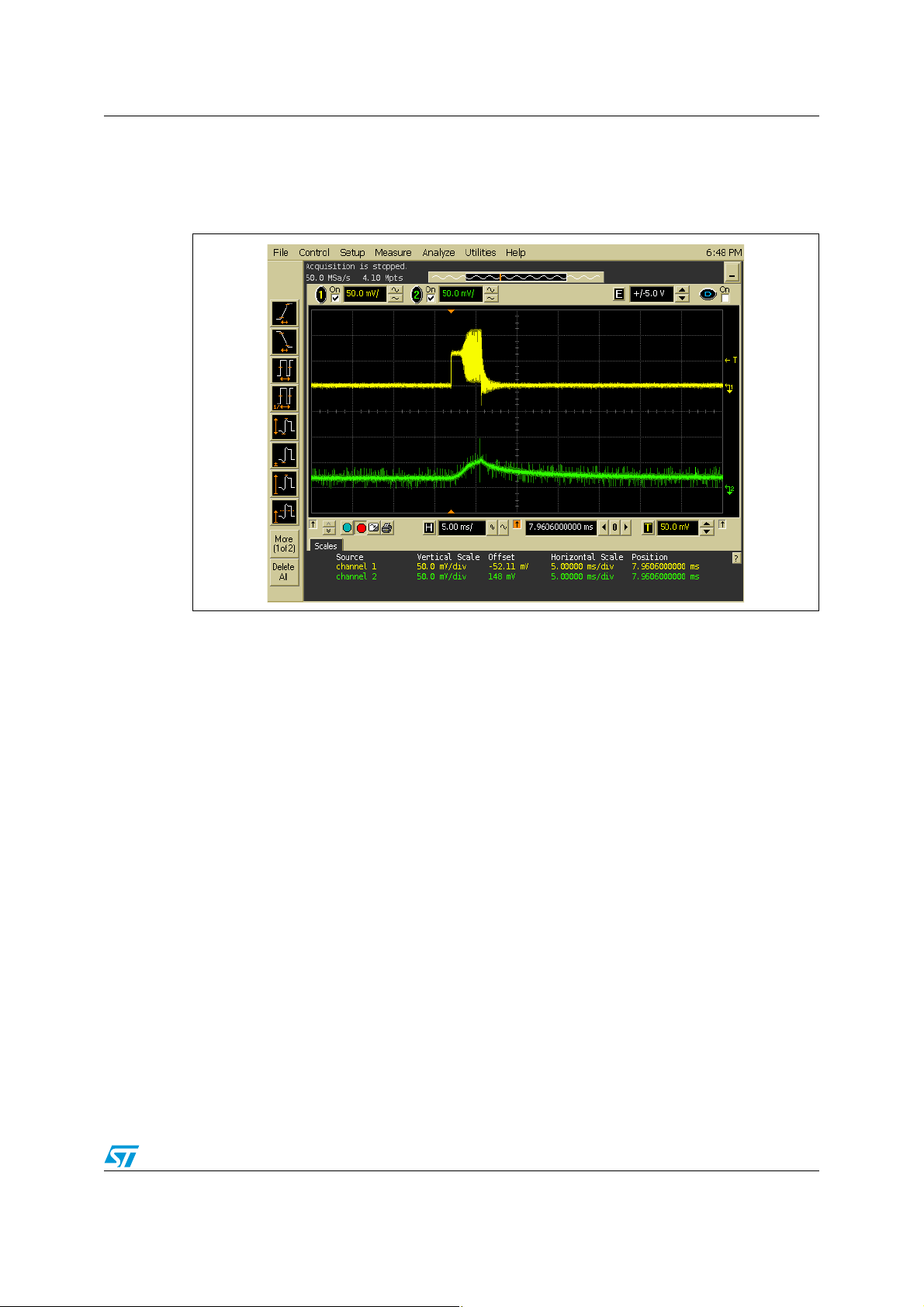
Figure 3 shows the device waking up from Hibernate state when pin IRQ_IN (green) goes
low. When the device returns to Ready state, the HF oscillator (yellow) restarts analog
resources.
Figure 3. Wakeup from Hibernate state
Doc ID 019046 Rev 2 17/34
Page 18

Power consumption considerations AN3433
3.2 Transition from Ready to Sleep state
This transition ensures low power consumption as well as a fast recovery (switch to Ready
state).
When the CR95HF or STRFNFCA receives an Idle command with the Sleep option, it only
partially disables its resources. In this state, power consumption will decrease from 2.5 mA
to approximately 20 µA.
The device can wake up from Idle state only at the end of pre-defined timeout or by an
external event (pin IRQ_IN
A basic Idle command used to wake up the device at the end of pre-defined timeout is:
>>> 0x07 0E 01 01 00 38 00 18 00 60 00 00 00 00 00 00
In this example, the timer uses only the LF oscillator. The timeout period is defined by the
following command parameters:
TO = 256*t
A basic Idle command used to wake up the device by an external event (pin IRQ_IN
>>> 0x07 0E 08 01 00 38 00 18 00 60 00 00 00 00 00 00
or SPI_SS goes low).
*WuPeriod*MaxSleep
LFO
) is:
A basic Idle command used to wake up the device by an external event (pin SPI_SS
>>> 0x07 0E 10 01 00 38 00 18 00 60 00 00 00 00 00 00
The device will only send its response after having returned to Ready state after an external
event is detected.
When the device wakes up from Sleep state, it restarts the external oscillator and all other
resources, including the selected communication interface, before returning to Ready state
and waiting for a new command.
In certain cases (mainly when using the UART), it may be necessary to use an Echo
command to re-synchronize the host and CR95HF or STRFNFCA device.
3.3 Wakeup by Tag Detection
The Tag Detection process requires the temporary use of internal resources such as the
13.56-MHz HF oscillator or the DAC which are usually switched off in WFE mode and only
turned on during an RF burst emission to determine if tag entered the device operating
range.
The delay (t
INACTIVE
WuPeriod parameter.
For a complete description of the Tag Detection process, see Appendix A: Tag detection
principle.
t
INACTIVE
In the example shown in Figure 4:
t
INACTIVE
) between two RF burst emissions is defined in the Idle command by the
= (WuPeriod+1)*t
= (32+1)*8 ms = 264 ms
) is:
REF
18/34 Doc ID 019046 Rev 2
Page 19

AN3433 Power consumption considerations
0x07 0E 0A 21 00 79 01 18 00 20 60 60 64 74 3F 08
Figure 4 illustrates a Tag Detection cycle.
Figure 4. Typical cycle in Tag Detection mode
1. In the above figure, yellow represents the 27.12-MHz (HFO) oscillator and the RF emission is in green.
Figure 5 shows a zoomed image of Figure 4 including the HFO stabilization time (OscStart)
and the DAC initialization time (DacStart).
Figure 5. Restart of resources in Tag Detection mode
1. In the above figure, yellow represents the 27.12-MHz (HFO) oscillator and the RF emission is in green.
Doc ID 019046 Rev 2 19/34
Page 20

Power consumption considerations AN3433
The duration of the RF burst (t
) is defined by SwingsCnt, the number of 13.56-MHz
SWING
pulses emitted. This value must be adjusted initially in the application environment to obtain
the best measurement stability.
t
SWING
= Swing * t
= 64 * 73 ns = 4.5 µs
HFO
Increasing the SwingsCnt value improves DAC accuracy, but also increases the power
consumption of the RF drivers (pin VPS_TX).
When using the CR95HF or STRFNFCA demoboard, we recommend a SwingsCnt value of
0x3F. This value corresponds to 64 RF pulses per burst (in blue) for a duration of 4.7 µs as
shown in Figure 6. This results in a mean power consumption of 100 µA.
Figure 6. RF burst in Tag Detection mode
1. In the above figure, yellow represents the 27.12-MHz (HFO) oscillator and the RF emission is in green.
20/34 Doc ID 019046 Rev 2
Page 21
AN3433 Power consumption considerations
The device consumes the most power during RF emissions in Tag Detection mode
(Figure 7). The User can regulate the mean consumption by modifying the period between
bursts (Wuperiod).
Figure 7. Power consumption in Tag Detection mode
1. In the above figure, yellow represents the 27.12-MHz (HFO) oscillator and the device power consumption
is in green.
Doc ID 019046 Rev 2 21/34
Page 22

Tag detection principle AN3433
Appendix A Tag detection principle
The Tag Detection process requires the temporary use of internal resources such as the
13.56 MHz HF oscillator or the DAC which are usually switched off in WFE mode and only
turned on during an RF burst emission to determine if tag entered the device operating
range.
To detect the presence of a tag, the device measures a portion of the device antenna’s
current using the DAC (DacLevel) and compares this value to a reference value (CalRef)
determined in the same way when the application is initialized.
To do this, once the HF oscillator is stabilized, the device emits an RF burst and monitors its
antenna current using its internal 64-bit DAC. This result is then compared to a reference
value established during the Tag Detection Calibration phase.
The device is initially calibrated by the user application in a free-air environment (no tags
present) in order to obtain a reference value (CalRef) that corresponds to the basic
threshold of its comparator.
When a new measurement of the antenna’s current results in a value different from the
CalRef value, a tag is probably present in the RF field.
To reduce the margin of error for false detections, in addition to comparing the value of the
measured antenna current (DacLevel) to the reference value (CalRef), the device checks
that the measured value is within a given range:
DacDataL < DacLevel < DacDataH
Using range limits ensures a stable Tag Detection process. We usually choose:
DacDataL = CalRef – 0x08 and DacDataH = CalRef + 0x08
The parameters that define measurement resources, oscillator and DAC setup times or RF
burst duration, can be individually adjusted within the Idle command parameters, but they
must remain unchanged between the calibration and tag detection periods.
We recommend for the HF oscillator and DAC stabilization times (OscStart and DacStart,
respectively) using a minimum value of 0x60 that corresponds to a duration of 3 ms
(96 * t
LFO
).
22/34 Doc ID 019046 Rev 2
Page 23

AN3433 Tag detection principle
-36
$AC$ATA(
$AC$ATA,
!NTENNACURRENT
#AL2EF
2&BURSTINTIME
"ASICSETUP.OTAG
INOPERATINGVOLUME
3ETUPCHANGE4AGPROBABLY
INOPERATINGVOLUME
2&BURSTINTIME
#AL2EFCALIBRATION
MEASUREMENT
-EASUREDCURRENT
-EASUREDCURRENT
.OTAGDETECTION2&FIELD
BETWEENCALIBRATIONLIMITS
7AKEUPAFTERTAGDETECTION2&FIELD
EXCEEDSCALIBRATIONLIMITS
Figure 8. Tag detection principle (levels of antenna current)
A.1 Tag detection sequence
Several parameters of the tag detection sequence can be managed to optimize the wakeup
time or power budget.
By adjusting the inactivity time (t
INACTIVE
), the time between two tag detection RF bursts, the
power consumption can be modified through the WuPeriod parameter in the Idle command
(usually set to 0x20).
t
INACTIVE
= (WuPeriod+1)*t
REF
The user can choose to limit number of tag detection trials by adjusting the MaxSleep value.
This MaxSleep value is validated only when the correct Wakeup condition is set (Bit 0 of the
Wakeup condition register). Otherwise, the tag detection sequence is repeated continuously
until a wakeup event occurs.
A minimum duration of 3 ms must be set for the DAC and HFO setup times to obtain a good
accuracy of measure. This phase is a high consumption period, so we recommend keeping
it short. These setup times (DacStart and OscStart, respectively) are defined in the Idle
command and are both usually set to 0x60.
The RF burst length (SwingCnt) corresponds to the acquisition time necessary for the DAC.
It must be sufficient to obtain a reproducible measurement, but it means turning on the RF
driver which consumes the most energy. The SwingCnt parameter value is defined in the
Idle command and is usually set to 0x3F.
Doc ID 019046 Rev 2 23/34
Page 24

Tag detection principle AN3433
-36
2EADY
2EADY
$!#AND(&/
ENABLED
2&BURST)DLE
CONSUMPTION
^M!
^!
^M!
^!
)603)60348
4IME
!NTENNACURRENT
T
37).'
. .
. -AX3LEEP
2&
BURST
/SC3TART
$AC3TART
4IME
T
4/
-EASUREDCURRENT
T
).!#4)6%
Figure 9 illustrates a time-limited tag detection sequence where no tag is present in the
operating volume, none is detected and the device wakes up after a timeout. (The lower part
of the figure illustrates the power consumption profile.)
A basic Idle command used for a time-limited tag detection sequence is:
>>> 0x 07 0E 0B 21 00 79 01 18 00 20 60 60 54 64 3F 08
Figure 9. Time-limited tag detection sequence (display of device consumption)
24/34 Doc ID 019046 Rev 2
Page 25

AN3433 Tag detection principle
Figure 10 illustrates an unlimited tag detection sequence interrupted by a tag entering the
device operating volume. (The lower part of the figure illustrates the power consumption
profile during tag detection and after the device automatically returns to Ready state.)
A basic Idle command used for an unlimited tag detection sequence is:
>>> 0x 07 0E 0A 21 00 79 01 18 00 20 60 60 54 64 3F 08
Figure 10. Tag detection sequence, Wakeup after tag entry in operating volume
(display of device consumption)
!NTENNACURRENT
)603)60348
$!#AND(&/
.O4AGINOPERATINGVOLUME
2&
T
T
37).'
ENABLED
).!#4)6%
BURST
CONSUMPTION
$AC$ATA(
$AC$ATA,
-EASUREDCURRENT
2&BURST)DLE
4AGENTRYINOPERATINGVOLUME
4AG$ETE C T I O N
4IME
2EADY2EADY
4IME
-36
Doc ID 019046 Rev 2 25/34
Page 26

Tag Detection Calibration process AN3433
Appendix B Tag Detection Calibration process
The Tag Detection Calibration process must be performed when the application is initialized.
A fast and efficient dichotomist flow in 8 steps is proposed to achieve best results.
Before starting this flow, the user must define its basic setup which consists in defining the
following parameters using the Idle command. These parameters are described in
Section 2.3: Idle command parameters on page 9.
When using the CR95HF or STRFNFCA demoboard and development kit, the following
values are recommended:
● Wakeup condition: 0x03 (tag detection or timeout)
● EnterCtrlL/EnterCtrlH, WUCtrlL/WUCtrlH, and LeaveCtlL/LeaveCtrlH values define
internal parameters settings during the tag detection process. We recommend:
>>> 0xA1 00 F8 01 18 00
● MaxSleep: MUST be set to ‘01’ in Tag Detection Calibration process for immediate
wakeup. This means that only one detection impulse will be sent and immediately
afterwards the device will exit Tag Detection Calibration mode.
● Oscillator and DAC stabilization times. We recommend: 0x60
● Number of 13.56 MHz swings during tag detection (SwingsCnt), we recommend using
0x3F to obtain a good reproducibility of measurements.
● WakeUp period. This parameter is not used during the Tag Detection Calibration
process.
● The Host can then use the RdReg command to read the Wakeup condition register to
determine the cause of the wakeup or check the reply code.
A basic Tag Detection Calibration command is:
>>> 0x 07 0E 03 A1 00 F8 01 18 00 20 60 60 00 xx 3F 01
B.1 Tag Detection Calibration algorithm
To determine the RF Field reference level (CalRef) corresponding to your application setup,
you must use the Tag Detection Calibration function (TagCal).
For calibration purposes, parameters are set to execute only one RF field evaluation before
leaving Tag Detection state.
This is achieved by setting the WU condition parameter to 0x03 (wakeup upon timeout or
tag detection) and the MaxSleep value to 0x01 forcing the CR95HF or STRFNFCA to leave
the Tag Detection state after only one attempt.
The value of the Wakeup flag is updated to the following value each time the device leaves
Tag Detection state.
Here, the WakeUp_n variable corresponds to the third byte of the device Idle command
reply.
If the measured antenna current is between DacDataL and DacDataH, the wakeup
event will be a timeout: WakeUp_n = 1
If the measured antenna current is less than DacDataL or greater than DacDataH, the
wakeup event will be a tag detection: WakeUp_n = 2
26/34 Doc ID 019046 Rev 2
Page 27

AN3433 Tag Detection Calibration process
During the calibration process, DacDataL is set to 0x00 and the reference level is
determined changing only the DacDataH parameter.
The reference level corresponds to the switching level between wakeup sources. It is
determined using the fast dichotomist process in 8 steps;
The Tag Detection Calibration command is formatted as follows:
TagCal (Ref_H) = 0x07 0E 03 A1 00 F8 01 18 00 20 60 60 00 Ref_H 3F 01
All the parameters are predefined to fit applicative requests in terms of wakeup sources and
power consumption. A compromise must be established between the detection period and
power consumption.
TagDet (64,74, or DacDataL and DacDataH, respectively) is defined using the command:
>>> 0x07 0E 0B 21 00 79 01 18 00 20 60 60 64 74 3F 00
B.2 Tag Detection calibration command
The Tag Detection Calibration command (TagCal) is a special setting of the Tag Detection
command (TagDet) for which the only variable is Ref_H.
>>> 0x07 0E 03 A1 00 F8 01 18 00 01 60 60 00 XX 3F 00
<<< 0x00 01 01 (in the event of a timeout)
or
<<< 0x00 01 02 (in the event of a tag detection in the RF field)
Here, the third byte (the WakeUp_n variable) defines the Wakeup event.
It is also possible to directly use the Wakeup Flag command: 0x08 03 62 01 00
Read Wakeup Flag reply:
– In case of timeout: 0x00 01 01 (WakeUp_n = 0x01)
– In case of Tag Detection: 0x00 01 02 (WakeUp_n = 0x02)
In Figure 11, the function TagCal (0xRef_n) corresponds to the execution of the following
device Idle command:
>>> 0x07 0E 03 A1 00 F8 01 18 00 20 60 60 00 0xRef_n 3F 01
<<< 0x00 01 01 (in the event of a timeout)
or
<<< 0x00 01 02 (in the event of a tag detection in the RF field)
Here, the third byte (the WakeUp_n variable) defines the Wakeup event.
Doc ID 019046 Rev 2 27/34
Page 28

Tag Detection Calibration process AN3433
Figure 11. Dichotomist algorithm for tag detection calibration
3TART
N2EF?&#
NN
7AKE5P?2EAD2EPLYOR7AKEUP&LAG
%XECUTE4AG#ALX
7AKE5P?
.
9
%XECUTE4AG#ALX&#
7AKE5P?2EAD2EPLYOR7AKEUP&LAG
7AKE5P?
9
N
X2EF?NX2EF?N;>7AKE5P?NXX>N=
%XECUTE4AG#ALX2EF?N
7AKE5P?N2EADREPLYOR7AKEUP&LAG
.
N
9
X#AL2EFX2EF?X7AKE5P?n
$AC$ATA,X#AL2EFX
$AC$ATA(X#AL2EFX
3TOP
.
%22/2
-36
28/34 Doc ID 019046 Rev 2
Page 29

AN3433 Example of CR95HF tag detection calibration process
Appendix C Example of CR95HF tag detection calibration
process
From this Revision 1.1, we can directly use the CR95HF reply during Tag Detection
Calibration or Tag Detection sequences and avoid using the R
This is a dichotomic approach to quickly converge to the DacDataRef value for which a
wakeup event switches from tag detection to timeout. In this process, only the DacDataH
parameter is changed in successive Idle commands. And we look at the wakeup event reply
to decide the next step.
<<< 00 01 02 corresponds to a Tag Detection (WakeUp_n = 2)
<<< 00 01 01 corresponds to a Timeout (WakeUp_n = 1)
REM, Tag Detection Calibration Test
REM, Sequence: Power-up Tag Detect Wake-up by Tag Detect (1 try
measurement greater or equal to DacDataH) or Timeout
REM, CMD 07 0E 03 A100 F801 1800 20 60 60 00 XX 3F 01
REM, 03 WU source = TagDet or Timeout
DREG command.
REM, A100 Initial Dac Compare
REM, F801 Initial Dac Compare
REM, 1800 HFO
REM, 20 WuPeriod = 32, Inactivity period = 256ms (LFO @ 32kHz)
REM, 60 Osc 3ms (LFO @ 32kHz)
REM, 60 Dac 3ms (LFO @ 32kHz)
REM, 00 DacDataL = minimum level (floor)
REM, xx DacDataH 00 = minimum level (ceiling)
REM, 3F Swing 13.56 4.6 us
REM, 01 Maximum number of Sleep before Wakeup 2
REM, Tag Detection Calibration Test
REM, During tag detection calibration process DacDataL = 0x00
REM, We execute several tag detection commands with different
DacDataH values to determine DacDataRef level corresponding to
CR95HF application set-up
REM, DacDataReg value corresponds to DacDataH value for which Wakeup event switches from Timeout (0x01) to Tag Detect (0x02)
REM, Wake-up event = Timeout when DacDataRef is between DacDataL
and DacDataH
Doc ID 019046 Rev 2 29/34
Page 30

Example of CR95HF tag detection calibration process AN3433
REM, Search DacDataref value corresponding to value of DacDataH for
which Wake-up event switches from Tag Detect (0x02) to Timeout
(0x01)
REM, Step 0: force wake-up event to Tag Detect (set DacDataH = 0x00)
REM, With these conditions Wake-Up event must be Tag Detect
>>> CR95HFDLL_STCMD, 01 070E03A100F801180020606000003F01
<<< 00 01 02
REM, Read Wake-up event = Tag Detect (0x02); if not, error .
REM, Step 1: force Wake-up event to Timeout (set DacDataH = 0xFC
REM, With these conditions, Wake-Up event must be Timeout
>>> CR95HFDLL_STCMD, 01 070E03A100F801180020606000FC3F01
<<< 00 01 01
REM, Read Wake-up event = Timeout (0x01); if not, error.
REM, Step 2: new DacDataH value = previous DacDataH +/- 0x80
REM, If previous Wake-up event was Timeout (0x01) we must decrease
DacDataH (-0x80)
>>> CR95HFDLL_STCMD, 01 070E03A100F8011800206060007C3F01
<<< 00 01 01
REM, Read Wake-up event = Timeout (0x01) or Wake-up event = Tag
Detect (0x02)
REM, Step 3: new DacDataH value = previous DacDataH +/- 0x40
REM, If previous Wake-up event was Timeout (0x01), we must decrease
DacDataH (-0x40); else, we increase DacDataH (+ 0x40)
>>> CR95HFDLL_STCMD, 01 070E03A100F8011800206060003C3F01
<<< 00 01 02
REM, Read Wake-up event = Timeout (0x01) or Wake-up event = Tag
Detect (0x02)
REM, Step 4: new DacDataH value = previous DacDataH +/- 0x20
REM, If previous Wake-up event was Timeout (0x01), we must decrease
DacDataH (-0x20); else, we increase DacDataH (+ 0x20)
>>> CR95HFDLL_STCMD, 01 070E03A100F8011800206060005C3F01
<<< 00 01 02
30/34 Doc ID 019046 Rev 2
Page 31

AN3433 Example of CR95HF tag detection calibration process
REM, Read Wake-up event = Timeout (0x01) or Wake-up event = Tag
Detect (0x02)
REM, Step 5: new DacDataH value = previous DacDataH +/- 0x10
REM, If previous Wake-up event was Timeout (0x01), we must decrease
DacdataH (-0x10); else, we increase DacDataH (+ 0x10)
>>> CR95HFDLL_STCMD, 01 070E03A100F8011800206060006C3F01
<<< 00 01 02
REM, Read Wake-up event = Timeout (0x01) or Wake-up event = Tag
Detect (0x02)
REM, Step 6: new DacDataH value = previous DacDataH +/- 0x08
REM, If previous Wake-up event was Timeout (0x01), we must decrease
DacDataH (-0x08); else, we increase DacDataH (+ 0x08)
>>> CR95HFDLL_STCMD, 01 070E03A100F801180020606000743F01
<<< 00 01 01
REM, Read Wake-up event = Timeout (0x01) or Wake-up event = Tag
Detect (0x02)
REM, Step 7: new DacDataH value = previous DacDataH +/- 0x04
REM, If previous Wake-up event was Timeout (0x01), we must decrease
DacDataH (-0x04); else, we increase DacDataH (+ 0x04)
>>> CR95HFDLL_STCMD, 0 1070E03A100F801180020606000703F01
<<< 00 01 01
REM, Read Wake-up event = Timeout (0x01) or Wake-up event = Tag
Detect (0x02)
REM, If last Wake-up event = Tag Detect (0x02), search DacDataRef =
last DacDataH value
REM, If last Wake-up event = Timeout (0x01), search DacDataRef =
last DacDataH value -4
REM, For tag detection usage, we recommend setting DacDataL =
DacDataRef -8 and DacDataH = DacDataRef +8
>>> CR95HFDLL_STCMD, 01 070E0B21007901180020606064743F01
<<< 00 01 01
Doc ID 019046 Rev 2 31/34
Page 32

Example of CR95HF tag detection command using results of tag detection calibration AN3433
Appendix D Example of CR95HF tag detection command
using results of tag detection calibration
This is an example of a Tag Detection command when a tag is not present in the RF
operating volume using CR95HF revision 1.1.:
>>> CR95HFDll_STCmd, 01 070E0B21007901180020606064743F01
<<< 00 01 01 Wake-up event = Timeout (0x01)
>>> CR95HFDll_STCmd, 01 0803620100
<<< 00 01 01
This is an example of a Tag Detection command when a tag is present in the RF operating
volume using CR95HF revision 1.1.:
>>> CR95HFDll_STCmd, 01 070E0B21007901180020606064743F01
<<< 00 01 02 Wake-up event = Tag Detect (0x02)
>>> CR95HFDll_STCmd, 01 0803620100
<<< 00 01 02
32/34 Doc ID 019046 Rev 2
Page 33

AN3433 Revision history
Revision history
Table 7. Document revision history
Date Revision Changes
05-Dec-2011 1 Initial release.
23-Feb-2012 2 Updated the document throughout to include the STRFNFCA device.
Doc ID 019046 Rev 2 33/34
Page 34

AN3433
Please Read Carefully:
Information in this document is provided solely in connection with ST products. STMicroelectronics NV and its subsidiaries (“ST”) reserve the
right to make changes, corrections, modifications or improvements, to this document, and the products and services described herein at any
time, without notice.
All ST products are sold pursuant to ST’s terms and conditions of sale.
Purchasers are solely responsible for the choice, selection and use of the ST products and services described herein, and ST assumes no
liability whatsoever relating to the choice, selection or use of the ST products and services described herein.
No license, express or implied, by estoppel or otherwise, to any intellectual property rights is granted under this document. If any part of this
document refers to any third party products or services it shall not be deemed a license grant by ST for the use of such third party products
or services, or any intellectual property contained therein or considered as a warranty covering the use in any manner whatsoever of such
third party products or services or any intellectual property contained therein.
UNLESS OTHERWISE SET FORTH IN ST’S TERMS AND CONDITIONS OF SALE ST DISCLAIMS ANY EXPRESS OR IMPLIED
WARRANTY WITH RESPECT TO THE USE AND/OR SALE OF ST PRODUCTS INCLUDING WITHOUT LIMITATION IMPLIED
WARRANTIES OF MERCHANTABILITY, FITNESS FOR A PARTICULAR PURPOSE (AND THEIR EQUIVALENTS UNDER THE LAWS
OF ANY JURISDICTION), OR INFRINGEMENT OF ANY PATENT, COPYRIGHT OR OTHER INTELLECTUAL PROPERTY RIGHT.
UNLESS EXPRESSLY APPROVED IN WRITING BY TWO AUTHORIZED ST REPRESENTATIVES, ST PRODUCTS ARE NOT
RECOMMENDED, AUTHORIZED OR WARRANTED FOR USE IN MILITARY, AIR CRAFT, SPACE, LIFE SAVING, OR LIFE SUSTAINING
APPLICATIONS, NOR IN PRODUCTS OR SYSTEMS WHERE FAILURE OR MALFUNCTION MAY RESULT IN PERSONAL INJURY,
DEATH, OR SEVERE PROPERTY OR ENVIRONMENTAL DAMAGE. ST PRODUCTS WHICH ARE NOT SPECIFIED AS "AUTOMOTIVE
GRADE" MAY ONLY BE USED IN AUTOMOTIVE APPLICATIONS AT USER’S OWN RISK.
Resale of ST products with provisions different from the statements and/or technical features set forth in this document shall immediately void
any warranty granted by ST for the ST product or service described herein and shall not create or extend in any manner whatsoever, any
liability of ST.
ST and the ST logo are trademarks or registered trademarks of ST in various countries.
Information in this document supersedes and replaces all information previously supplied.
The ST logo is a registered trademark of STMicroelectronics. All other names are the property of their respective owners.
© 2012 STMicroelectronics - All rights reserved
STMicroelectronics group of companies
Australia - Belgium - Brazil - Canada - China - Czech Republic - Finland - France - Germany - Hong Kong - India - Israel - Italy - Japan -
Malaysia - Malta - Morocco - Philippines - Singapore - Spain - Sweden - Switzerland - United Kingdom - United States of America
www.st.com
34/34 Doc ID 019046 Rev 2
 Loading...