ST AN3430 APPLICATION NOTE

AN3430

Application note

How to achieve the lowest current consumption with STM32F2xx

Introduction

In embedded microcontroller applications, designers and developers have specific tasks to solve and their solutions are influenced by the resources that are available and the constraints of cost, time, physical size and technology choice. At the heart of many good products, microcontrollers have a crucial influence on system power design and particularly in a brave new world that’s concerned with energy efficiency

The STM32F2xx is one of the best high-performance microcontrollers that can be used to achieve a complete embedded application with the lowest current consumption.

This application note is intended for system designers who require a software and hardware implementation overview of the low-power modes of the STM32F2xx products. It describes how to use the STM32F2xx product family in low-power mode and details the clock systems, register settings and firmware development methods in order to optimize the use of energy in applications where low power is the key.

This application note should be read in conjunction with the datasheet of the relevant STM32F2xx product and the STM32F2xx reference manual. For information on programming, erasing and protection of the internal Flash memory please refer to the STM32F2xx Flash programming manual.

The STM32F2xx datasheets, the reference and Flash programming manuals are all available from the STMicroelectronics website www.st.com.

August 2011

Doc ID 019009 Rev 1

1/38

www.st.com

Contents

AN3430


Contents

1

Power consumption factors . . . . . . . . . . . . . . . . . . . . . . . . . . . . . . . . . . .

3

2

STM32F2 low power design . . . . . . . . . . . . . . . . . . . . . . . . . . . . . . . . . . .

4


2.1 STM32F2 hardware design . . . . . . . . . . . . . . . . . . . . . . . . . . . . . . . . . . . .

4

2.1.1 Internal supply structure . . . . . . . . . . . . . . . . . . . . . . . . . . . . . . . . . . . . . 4 2.1.2 Hardware environment . . . . . . . . . . . . . . . . . . . . . . . . . . . . . . . . . . . . . . . 5 2.1.3 Clock management . . . . . . . . . . . . . . . . . . . . . . . . . . . . . . . . . . . . . . . . . 7

2.2 STM32F2 low power configuration . . . . . . . . . . . . . . . . . . . . . . . . . . . . . . . 9


2.2.1

Low power mode overview . . . . . . . . . . . . . . . . . . . . . . . . . . . . . . .

. . . . 9


2.2.2

Power consumption and wakeup time . . . . . . . . . . . . . . . . . . . . . . .

. . . 10


2.2.3

Voltage regulator configuration and impact on power consumption

. . . 14

3

STM32F2 low power firmware development . . . . . . . . . . . . . . . . . . .

. . 17

3.1 Firmware tips and tricks . . . . . . . . . . . . . . . . . . . . . . . . . . . . . . . . . . . . . . 17

3.1.1 Common firmware configuration . . . . . . . . . . . . . . . . . . . . . . . . . . . . . . 17 3.1.2 Special firmware configuration . . . . . . . . . . . . . . . . . . . . . . . . . . . . . . . . 20 3.1.3 Code optimization . . . . . . . . . . . . . . . . . . . . . . . . . . . . . . . . . . . . . . . . . 21

3.2 STM32F2 example of current consumption optimization . . . . . . . . . . . . . 21

3.2.1 Test environment . . . . . . . . . . . . . . . . . . . . . . . . . . . . . . . . . . . . . . . . . . 21 3.2.2 SPI_MASTER_NonOptimized firmware architecture . . . . . . . . . . . . . . . 24 3.2.3 Practical example of current optimization . . . . . . . . . . . . . . . . . . . . . . . 26

4

Conclusion . . . . . . . . . . . . . . . . . . . . . . . . . . . . . . . . . . . . . . . . . . . . . . . .

35

Appendix A Schematics . . . . . . . . . . . . . . . . . . . . . . . . . . . . . . . . . . . . . . . . . . . . .

36

Revision history . . . . . . . . . . . . . . . . . . . . . . . . . . . . . . . . . . . . . . . . . . . . . . . . . . . .

37

2/38

Doc ID 019009 Rev 1

AN3430

Power consumption factors


1 Power consumption factors

Information in this section is based on Proceedings of the IEEE, Vol.89, No.11, November 2001.

Power dissipated in CMOS circuits consists of several components as indicated in the following equation:

Ptotal = Pswitching + Pshortcircuit + Pstatic + Pleakage

The total current consumption is a sum of:

The power required to charge or switch a capacitive load (Pswitching),

Short circuit power consumed during output transitions of a CMOS gate as the input switches (Pshortcircuit),

Static power consumed by the device (Pstatic),

Leakage power consumed by the device (Pleakage).

Pswitching and Pshortcircuit components represent the dynamic power which is consumed when a device is actively changing state:

Pswitching depends on the capacitive load, the voltage level and the system

frequency: Pswitching = C * V² * f

Pshortcircuit occurs due to the overlapped conductance of both the PMOS and NMOS transistors forming a CMOS logic gate as the input signal transitions, this current draw depends on the average current drawn during the input transition and the voltage level: Pshortcircuit = Imean * V

Pstatic and Pleakage components represent the static power consumption which is negligible compared to dynamic consumption when the clock is running.

Pstatic is not usually a factor in pure CMOS designs, since static current is not drawn by a CMOS gate, but certain circuit structures such as sense amplifiers, voltage references, and constant current sources do exist in CMOS systems and contribute to overall power.

Pleakage is due to leakage currents from reversed biased PN junctions associated with the source and drain of MOS transistors, as well as subthreshold conduction currents. The leakage component is proportional to device technology and temperature.

Power consumption thus depends on:

Microcontroller unit (MCU) chip size: Technology used, number of transistors, analog features/peripherals embedded and used.

MCU supply voltage: The amount of current used in CMOS logic is directly proportional to the voltage of the power supply squared. Thus, power consumption may be reduced by lowering the MCU supply voltage.

Clock frequency: Power consumption may be reduced by decreasing the clock frequency when fast processing is not required by the application.

Operating mode: Power consumption varies depending on the mode a particular application is running in (CPU on/off, oscillator on/off,...).

For an application powered by a battery, consumption is very important. Usually, average consumption should be below a certain target to ensure an optimum battery lifetime.

Doc ID 019009 Rev 1

3/38

STM32F2 low power design

AN3430


2 STM32F2 low power design

2.1STM32F2 hardware design

To introduce STM32F2xx series as a high performance and low power microcontroller in the market requires that this new generation of STM32 family come with a challenge in terms of hardware design.

This hardware design contributes to the static and dynamic current consumption of the SMT32F2 microcontroller. This is why the CMOS technology used, as well as the system design changes from one microcontroller to another depending on the final target which will be covered by this microcontroller.

2.1.1Internal supply structure

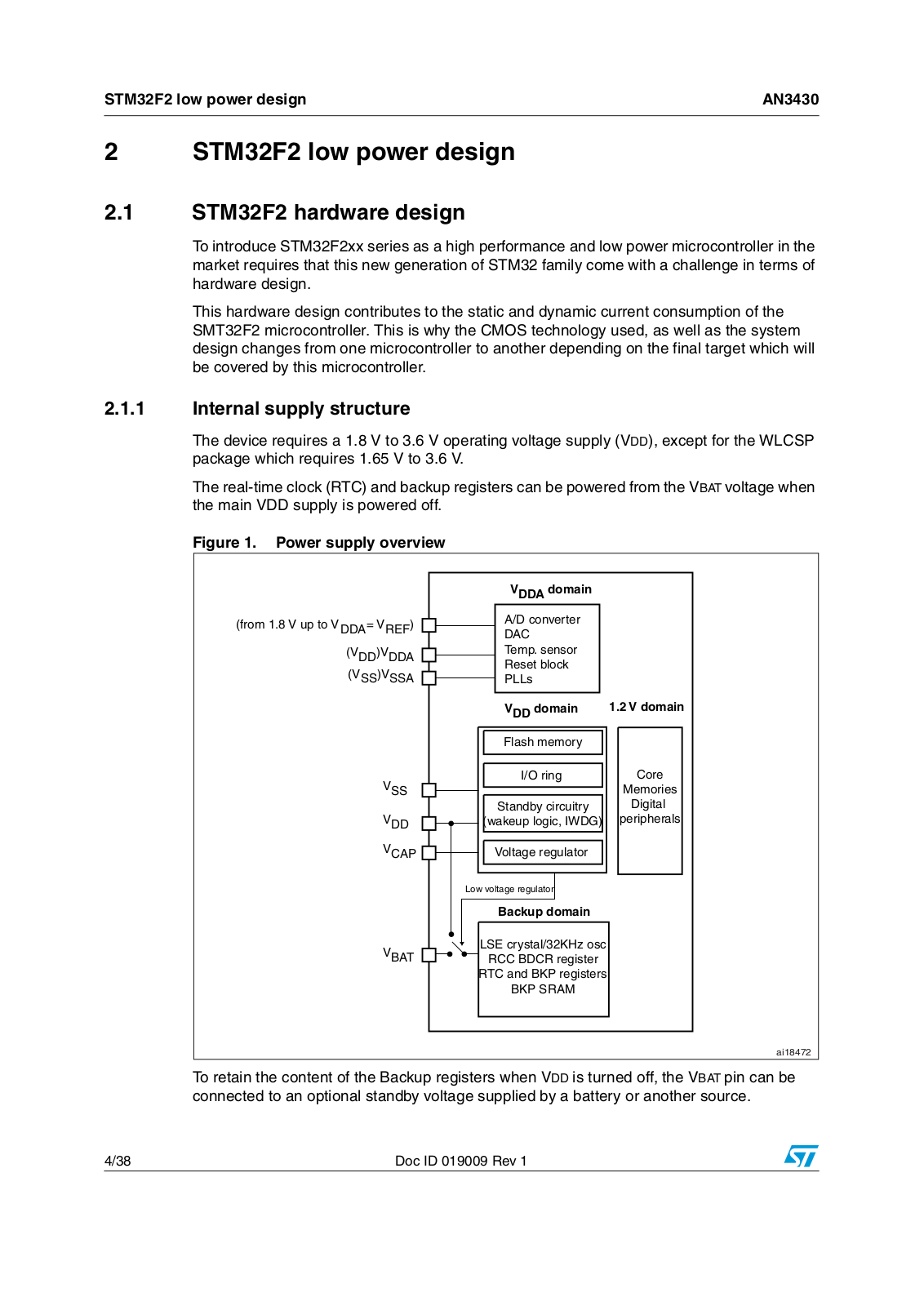
The device requires a 1.8 V to 3.6 V operating voltage supply (VDD), except for the WLCSP package which requires 1.65 V to 3.6 V.

The real-time clock (RTC) and backup registers can be powered from the VBAT voltage when the main VDD supply is powered off.

Figure 1. Power supply overview


6$$! DOMAIN


FROMR M66UP TOP6$$! 62%&

! $ CONVERTER


$!#


6$$ 6$$!

4EMP SENSOR


2ESETSBLOCK


633 633!


0,,S


6$$ DOMAIN

66DOMAIN


&LASHAMEMORY


633

) / RINGN

#ORE


-EMORIES


3TANDBYYCIRCUITRY

$IGITALI

6$$

WAKEUPULOGIC )7$'

PERIPHERALS

6#!0

6OLTAGE REGULATOR


,OWWVOLTAGE REGULATOR


"ACKUPUDOMAIN


6"!4

,3%3CRYSTAL +(Z OSC


2###"$#2 REGISTER


24# AND "+0 REGISTERS


"+0+32!-


AI

To retain the content of the Backup registers when VDD is turned off, the VBAT pin can be connected to an optional standby voltage supplied by a battery or another source.

4/38

Doc ID 019009 Rev 1

AN3430

STM32F2 low power design


The VBAT pin also powers the RTC unit, allowing the RTC to operate even when the main digital supply (VDD) is turned off. The switch to the VBAT supply is controlled by the power down reset (PDR) circuitry embedded in the Reset block.

An embedded regulator is used to supply the internal 1.2 V digital power, which was designed to consume the lowest current consumption needed in conjunction with low power mode used. There are three different operating modes:

In Run mode the regulator supplies full power to the 1.2 V domain (core, memories and digital peripherals).

In Stop mode the regulator supplies low power to the 1.2 V domain, preserving the content of registers and internal SRAM.

In Standby mode the regulator is powered down. The content of the registers and SRAM are lost except for the standby circuitry and the backup domain.

This regulator can also be bypassed by an external one which should supply directly the MCU with 1.2V injected on Vcap1 and Vcap2 pins (refer to Section 2.2.3).

2.1.2Hardware environment

In the real application, there are other hardware components, such as transceivers, external memories, Bluetooth chips or other microcontrollers which are connected to the STM32F2 in order to achieve the application target.

These components cause a current increase which affects both the static current consumption, depending on the PCB connection and hardware layout, and the dynamic consumption during MCU communications.

A well configured hardware design ensures the best current consumption for the final application.

For this reason we recommend following rules described in the Getting started with STM32F20xx/21xx MCU hardware development (AN3320).

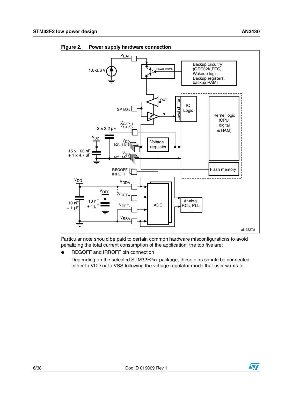
Figure 2 summarizes some of these rules:

Doc ID 019009 Rev 1

5/38

STM32F2 low power design

AN3430


Figure 2. Power supply hardware connection

6"!4

6

0OWERRSWITCH


"ACKUPUCIRCUITRY/3# + 24# 7AKEUPULOGIC

"ACKUPUREGISTERS BACKUPU2!-


/54


SHIFTER


'0 ) /S


)/


).


,EVEL

,OGIC


6#!0?


§ & 6#!0?


6$$

6$$


§ N&


633

§ § &


2%'/&&


6$$


)22/&&


6$$!


N&

62%&

62%&


N&


62%&


&


&


633!


6OLTAGE

REGULATOR

!NALOG !$# 2#S 0,,

+ERNELELOGICL#05 DIGITALI2!-

&LASHAMEMORY

AI D

Particular note should be paid to certain common hardware misconfigurations to avoid penalizing the total current consumption of the application; the top five are:

REGOFF and IRROFF pin connection

Depending on the selected STM32F2xx package, these pins should be connected either to VDD or to VSS following the voltage regulator mode that user wants to

6/38

Doc ID 019009 Rev 1

AN3430

STM32F2 low power design


configure. For more details, refer to section “Voltage regulator” in STM32F20xx/21xx datasheet for details.

Vcap_1 and Vcap_2 pin connection:

If the user wants the voltage regulator to be active during the application, these pins must be connected to GND through 2.2uF ceramic capacitors.

If the user wants to bypass the voltage regulator, these pins are used to inject the 1.2V supply from an external power supply. In this case, the 2.2uF capacitors should be disconnected and replaced by 100nF ceramic decoupling capacitors.

Unused pins not connected

All unused pins must be connected to ground through a 10K pull-down resistor to avoid external disturbance on the I/Os and increase the EMC performance.

Because clocks can be a major factor of a high current consumption, specific attention must be paid to all clock input and outputs related to the MCU or to other components on the board.

Designers should be aware that clocking other components on the board by MCU clock through one output pin (such as the MCO) will increase the current consumption due to the I/O switching frequency.

For this reason, it is up to the hardware designer to choose either routing a PCB wire from the MCO pin to other clock input components or use an external oscillator depending on the full set of clock requirements on the board (number of clock inputs and clock frequencies).

Note:

Refer to Section 3.2.3: Practical example of current optimization on page 26 for information


on the current consumption value versus clock output frequency.

If no external battery is used in the application, it is highly recommended to connect VBAT externally to VDD with a 100 nF decoupling capacitor.

2.1.3Clock management

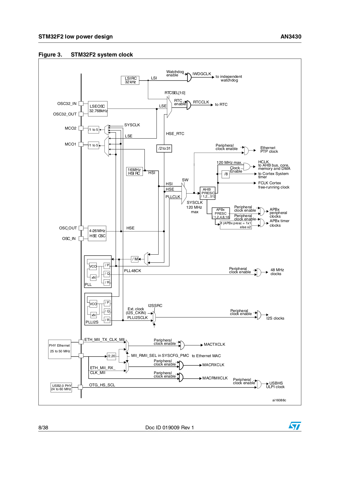
Three different clock sources can be used to drive the system clock (SYSCLK):

HSI oscillator clock

HSE oscillator clock

Main PLL (PLL) clock

The device has the two following secondary clock sources:

32 kHz low-speed internal RC (LSI RC), which drives the independent watchdog and, optionally, the RTC used for auto-wakeup from the stop/standby mode.

32.768 kHz low-speed external crystal (LSE crystal) which optionally drives the RTC clock (RTCCLK)

Each clock source can be switched on or off independently when it is not used to optimize power consumption.

Another source of energy saving is to bypass the HSE oscillator and clock the STM32F2 with an external clock source, if another clock already available on the board for other devices.

Doc ID 019009 Rev 1

7/38

STM32F2 low power design

AN3430


Figure 3. STM32F2 system clock


7ATCHDOG

)7$'#,+


ENABLE

TO INDEPENDENT


,3) 2#

,3)


WATCHDOG


K(Z


24#3%,; ==


/3# ?).


24#

24##,+


,3% /3#


,3%

ENABLE

TO 24#


/3# ?/54

K(Z


-#/


393#,+


TO


(3%?24#


,3%


-#/

TO


TO


0ERIPHERAL

%THERNET


CLOCKKENABLE


0404CLOCK


-(Z MAX

(#,+


-(Z


#LOCKK

TO !(" BUS CORE


MEMORYYANDA$-!


(3) 2#

(3)


%NABLE

TO #ORTEXX3YSTEM


37


TIMERM


(3)


,+ #ORTEX


(3%


!("


FREE RUNNING CLOCK


0,,#,+


02%3#


393#,+


0ERIPHERAL


-(Z

!0"X


!0"X


MAX


CLOCKKENABLE


02%3#


0ERIPHERAL

PERIPHERAL


CLOCKS


CLOCKKENABLE

!0"X TIMER


IF !0"X PRESC X


CLOCKS

/3#?/54


(3%


ELSE X

-(Z


/3#?).

(3%%/3#


-


6#/

0


0ERIPHERAL


-(Z


0,, #+


1


CLOCKKENABLE


X.


CLOCKS


0,,

2


6#/

0


) 332#


%XT CLOCKK


1


0ERIPHERAL


) 3?#+).


X.


CLOCKKENABLE


0,,) 3#,+


) 3 CLOCKS


0,,) 3

2


%4(?-))?48?#,+?-))

0ERIPHERAL


0(9(%THERNET


CLOCKKENABLE


-!#48#,+


TO -(Z


-))?2-))?3%, IN)393#&'?0-#

TO %THERNETE-!#


0ERIPHERAL


%4(?-))?28?


CLOCKKENABLE


-!#28#,+


#,+?-))


0ERIPHERAL


CLOCKKENABLE


-!#2-))#,+

0ERIPHERAL


53"(3

53" 0(9

/4'?(3?3#,


CLOCKKENABLE


5,0) CLOCK


TO -(Z


AI C

8/38

Doc ID 019009 Rev 1

AN3430

STM32F2 low power design


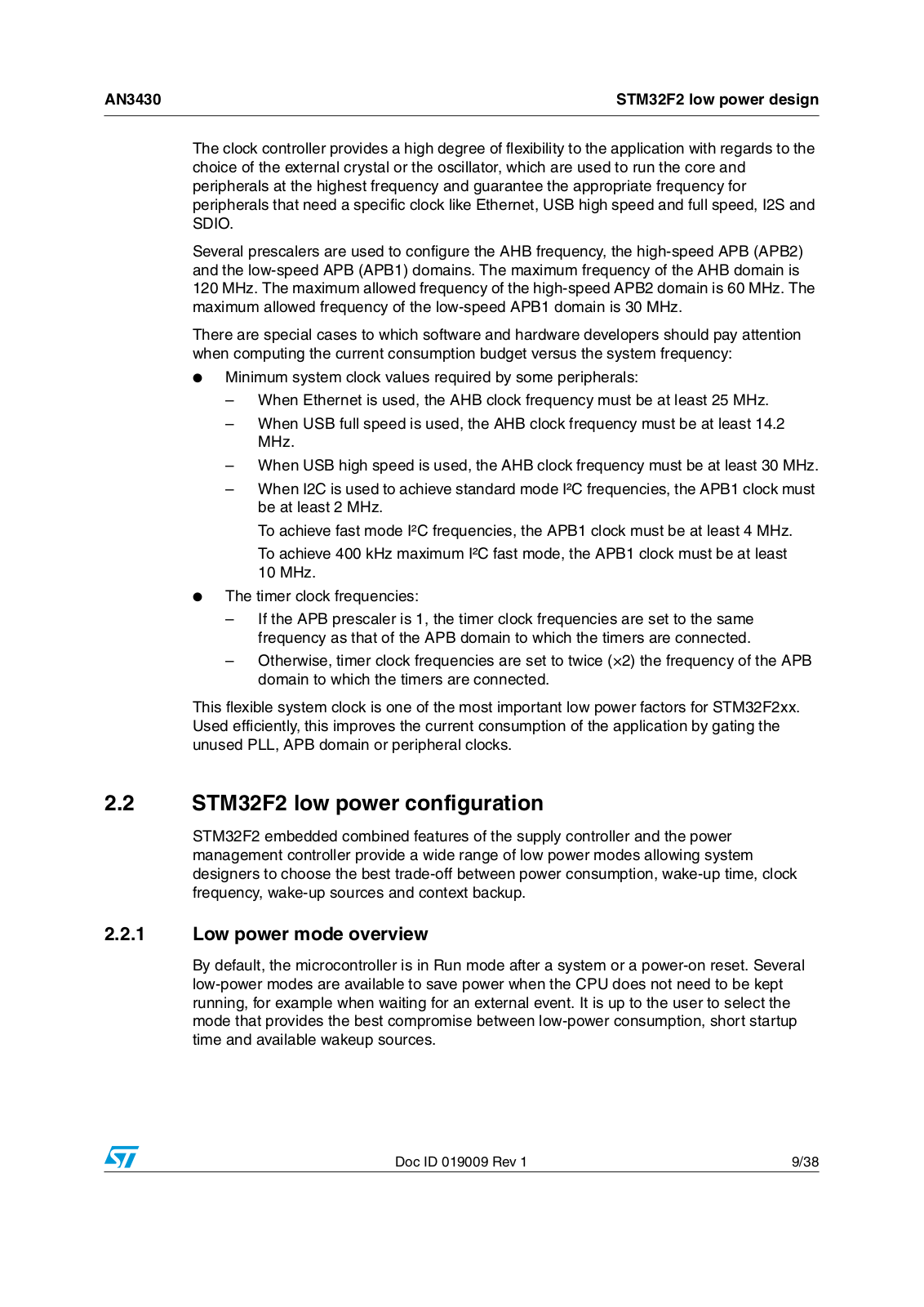
The clock controller provides a high degree of flexibility to the application with regards to the choice of the external crystal or the oscillator, which are used to run the core and peripherals at the highest frequency and guarantee the appropriate frequency for peripherals that need a specific clock like Ethernet, USB high speed and full speed, I2S and SDIO.

Several prescalers are used to configure the AHB frequency, the high-speed APB (APB2) and the low-speed APB (APB1) domains. The maximum frequency of the AHB domain is 120 MHz. The maximum allowed frequency of the high-speed APB2 domain is 60 MHz. The maximum allowed frequency of the low-speed APB1 domain is 30 MHz.

There are special cases to which software and hardware developers should pay attention when computing the current consumption budget versus the system frequency:

Minimum system clock values required by some peripherals:

When Ethernet is used, the AHB clock frequency must be at least 25 MHz.

When USB full speed is used, the AHB clock frequency must be at least 14.2 MHz.

When USB high speed is used, the AHB clock frequency must be at least 30 MHz.

When I2C is used to achieve standard mode I²C frequencies, the APB1 clock must be at least 2 MHz.

To achieve fast mode I²C frequencies, the APB1 clock must be at least 4 MHz.

To achieve 400 kHz maximum I²C fast mode, the APB1 clock must be at least 10 MHz.

The timer clock frequencies:

If the APB prescaler is 1, the timer clock frequencies are set to the same frequency as that of the APB domain to which the timers are connected.

Otherwise, timer clock frequencies are set to twice (×2) the frequency of the APB domain to which the timers are connected.

This flexible system clock is one of the most important low power factors for STM32F2xx. Used efficiently, this improves the current consumption of the application by gating the unused PLL, APB domain or peripheral clocks.

2.2STM32F2 low power configuration

STM32F2 embedded combined features of the supply controller and the power management controller provide a wide range of low power modes allowing system designers to choose the best trade-off between power consumption, wake-up time, clock frequency, wake-up sources and context backup.

2.2.1Low power mode overview

By default, the microcontroller is in Run mode after a system or a power-on reset. Several low-power modes are available to save power when the CPU does not need to be kept running, for example when waiting for an external event. It is up to the user to select the mode that provides the best compromise between low-power consumption, short startup time and available wakeup sources.

Doc ID 019009 Rev 1

9/38

STM32F2 low power design

AN3430


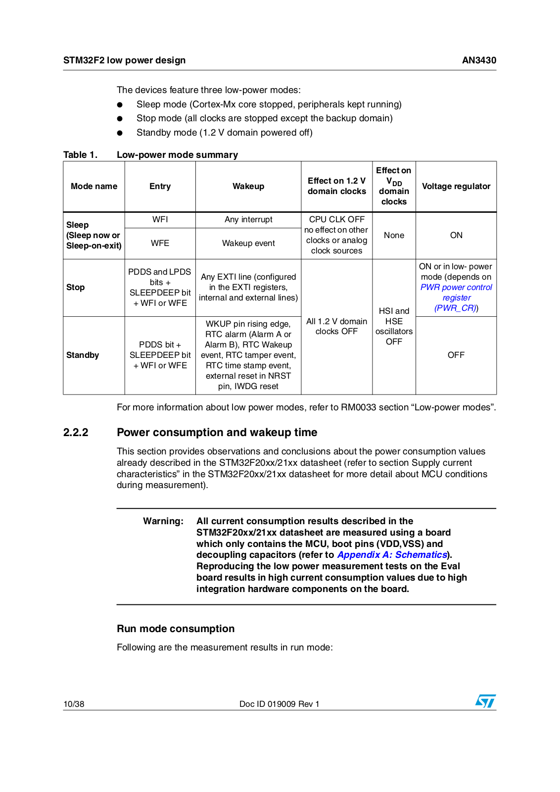
The devices feature three low-power modes:

Sleep mode (Cortex-Mx core stopped, peripherals kept running)

Stop mode (all clocks are stopped except the backup domain)

Standby mode (1.2 V domain powered off)

Table 1.

Low-power mode summary


Effect on


Mode name

Entry

Wakeup

Effect on 1.2 V

VDD

Voltage regulator


domain clocks

domain


clocks


Sleep


WFI

Any interrupt

CPU CLK OFF


no effect on other


(Sleep now or


None

ON

WFE

Wakeup event

clocks or analog

Sleep-on-exit)


clock sources


PDDS and LPDS


ON or in lowpower


Any EXTI line (configured


mode (depends on


bits +


Stop


in the EXTI registers,


PWR power control


SLEEPDEEP bit


internal and external lines)


register


+ WFI or WFE


HSI and

(PWR_CR))


WKUP pin rising edge,

All 1.2 V domain

HSE


clocks OFF

oscillators


RTC alarm (Alarm A or


OFF


PDDS bit +

Alarm B), RTC Wakeup


Standby


SLEEPDEEP bit

event, RTC tamper event,


OFF


+ WFI or WFE

RTC time stamp event,


external reset in NRST


pin, IWDG reset


For more information about low power modes, refer to RM0033 section “Low-power modes”.

2.2.2Power consumption and wakeup time

This section provides observations and conclusions about the power consumption values already described in the STM32F20xx/21xx datasheet (refer to section Supply current characteristics” in the STM32F20xx/21xx datasheet for more detail about MCU conditions during measurement).

Warning: All current consumption results described in the STM32F20xx/21xx datasheet are measured using a board which only contains the MCU, boot pins (VDD,VSS) and decoupling capacitors (refer to Appendix A: Schematics). Reproducing the low power measurement tests on the Eval board results in high current consumption values due to high integration hardware components on the board.

Run mode consumption

Following are the measurement results in run mode:

10/38

Doc ID 019009 Rev 1

ST AN3430 APPLICATION NOTE

AN3430

STM32F2 low power design


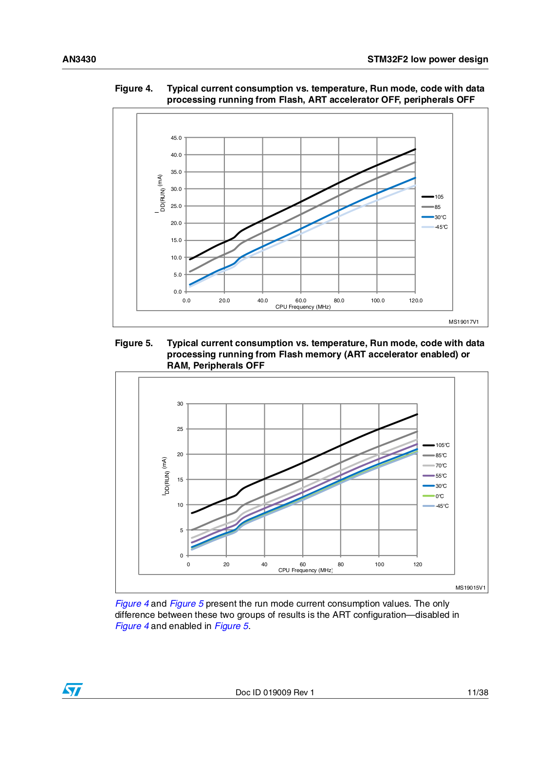
Figure 4. Typical current consumption vs. temperature, Run mode, code with data processing running from Flash, ART accelerator OFF, peripherals OFF

M!

25$$.

)

-3 6

Figure 5. Typical current consumption vs. temperature, Run mode, code with data processing running from Flash memory (ART accelerator enabled) or RAM, Peripherals OFF

M!

25$$.

)

-3 6

Figure 4 and Figure 5 present the run mode current consumption values. The only difference between these two groups of results is the ART configuration—disabled in

Figure 4 and enabled in Figure 5.

Doc ID 019009 Rev 1

11/38

STM32F2 low power design

AN3430


Observation:

Power consumption increases with clock frequency,

Power consumption increases with temperature,

Power consumption increases when disabling the ART accelerator.

Conclusion:

Use the appropriate clock frequency; do not over clock the system if this is not needed

Enable ART accelerator to reduce power consumption and increase the overall system speed and efficiency.

Sleep mode consumption and wakeup time

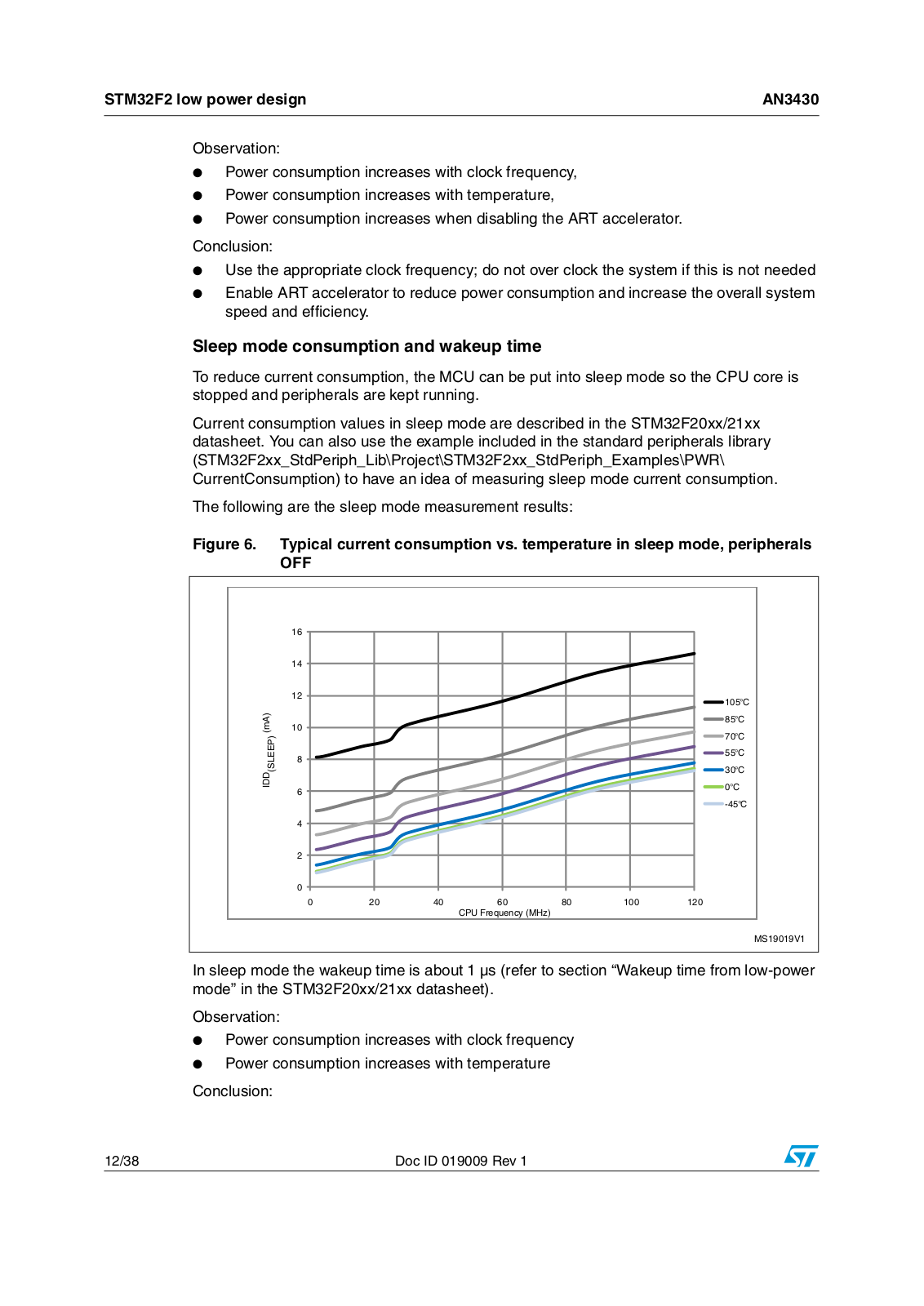
To reduce current consumption, the MCU can be put into sleep mode so the CPU core is stopped and peripherals are kept running.

Current consumption values in sleep mode are described in the STM32F20xx/21xx datasheet. You can also use the example included in the standard peripherals library (STM32F2xx_StdPeriph_Lib\Project\STM32F2xx_StdPeriph_Examples\PWR\ CurrentConsumption) to have an idea of measuring sleep mode current consumption.

The following are the sleep mode measurement results:

Figure 6. Typical current consumption vs. temperature in sleep mode, peripherals OFF

M!

3,%%0

)$$

#050&REQUENCY -(Z

-3 6

In sleep mode the wakeup time is about 1 µs (refer to section “Wakeup time from low-power mode” in the STM32F20xx/21xx datasheet).

Observation:

Power consumption increases with clock frequency

Power consumption increases with temperature

Conclusion:

12/38

Doc ID 019009 Rev 1

Loading...
+ 26 hidden pages