

Page 1
AN3408
Application note
Using LRIxx, LRISxx and M24Lxx-R products as NFC vicinity tags
Introduction
The NFC technology allows accessing standard ISO/IEC 15693 products such as
STMicroelectronics Dual interface EEPROMs (M24LR04E-R, M24LR16E-R and
M24LR64E-R) and ST ISO/IEC 15693 RFID tag products (LRI1K, LRI2K, LRIS2K and
LRIS64K).
The NFC forum specifies a data structure standard named NDEF allowing user data
exchange. Data can be either text, URI or picture.
RFID or NFC tag memory can embed NDEF messages and share it with different hosts
(reader, mobile phone).
This application note explains how to apply the NDEF format to STMicroelectronics ISO/IEC
15693 products (LRI1K, LRI2K, LRIS2K, LRIS64K and M24LR64-R).
Reference documents
■ ISO/IEC standards
– [15693-3]: ISO/IEC 15693-3: Identification cards - Contactless integrated circuit(s)
cards - Vicinity cards - Part 3: Anti-collision and transmission protocol
■ NFC forum documents
– [NDEF]: NFC Data Exchange Format (NDEF) Technical Specification; NFC Forum™;
NDEF 1.0
– [URI]: URI Record Type Definition document; NFC Forum™
– [RTD] : NFC Record Type Definition; NFC forum
– [BLUETOOTH] : Bluetooth Secure Simple Pairing Using NFC; NFC forum
– [TEXT] : Text Record Type Definition; NFC forum
– [TAG-2]: Type 2 Tag Operation Technical Specification; NFC Forum™; 1.1
■ ST documents
– LRI1K datasheet
– LRI2K datasheet
– LRIS2K datasheet
– LRIS64K datasheet
– M24LR64-R datasheet
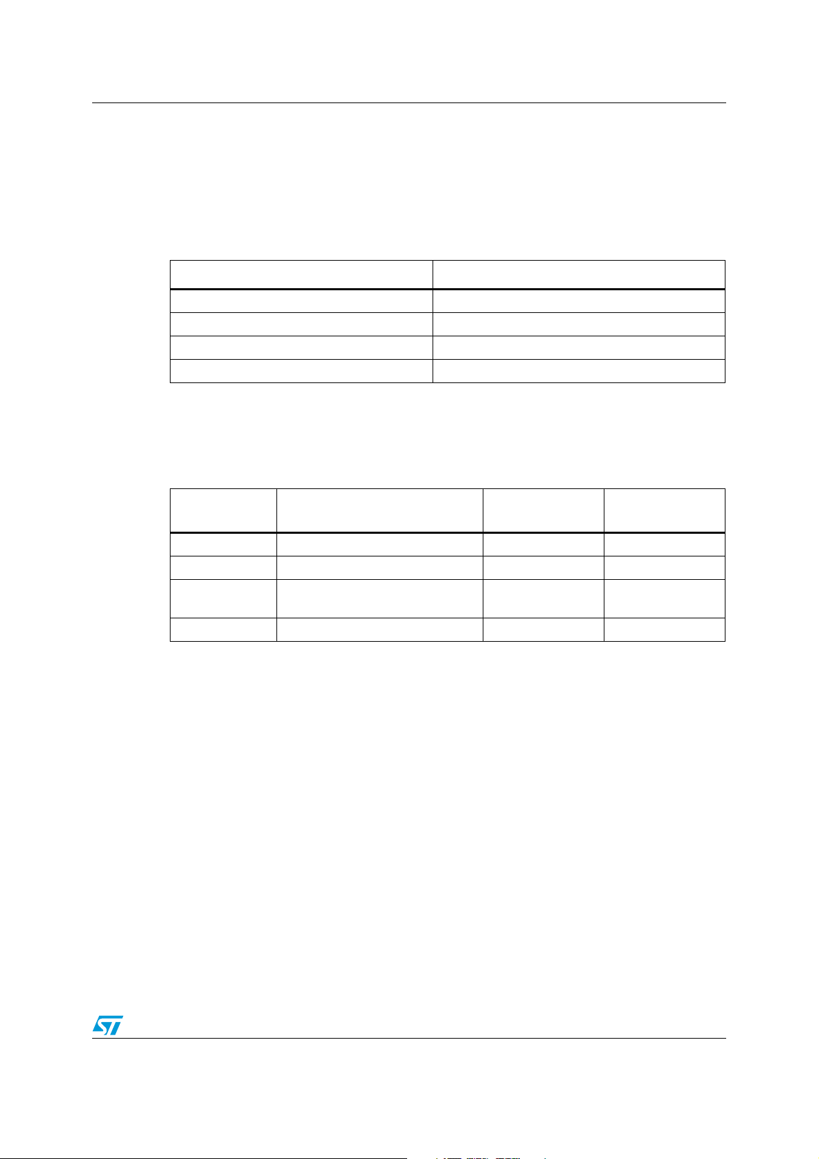
Ta bl e 1 lists the products concerned by this application note.
Table 1. Applicable products
Type Applicable products
Dual interface EEPROMs M24LR04E-R, M24LR16E-R and M24LR64E-R
RFID & RF Memory ICs LRI1K, LRI2K, LRIS2K and LRIS64K
July 2012 Doc ID 018867 Rev 2 1/37
www.st.com
Page 2

Contents AN3408
Contents
1 Memory organization for STMicroelectronics
ISO/IEC 15693 products . . . . . . . . . . . . . . . . . . . . . . . . . . . . . . . . . . . . . . 6
1.1 User memory area . . . . . . . . . . . . . . . . . . . . . . . . . . . . . . . . . . . . . . . . . . . 6
1.2 DSFID and AFI system area . . . . . . . . . . . . . . . . . . . . . . . . . . . . . . . . . . . 7
1.3 Unique identifier . . . . . . . . . . . . . . . . . . . . . . . . . . . . . . . . . . . . . . . . . . . . . 7
1.4 Protection system . . . . . . . . . . . . . . . . . . . . . . . . . . . . . . . . . . . . . . . . . . . . 7
2 NDEF data . . . . . . . . . . . . . . . . . . . . . . . . . . . . . . . . . . . . . . . . . . . . . . . . . 8
2.1 Overview . . . . . . . . . . . . . . . . . . . . . . . . . . . . . . . . . . . . . . . . . . . . . . . . . . 8
2.2 Capability container field . . . . . . . . . . . . . . . . . . . . . . . . . . . . . . . . . . . . . . 8
2.3 NDEF message using TLV format . . . . . . . . . . . . . . . . . . . . . . . . . . . . . . 10
2.3.1 T field values . . . . . . . . . . . . . . . . . . . . . . . . . . . . . . . . . . . . . . . . . . . . . 10
2.3.2 L field format . . . . . . . . . . . . . . . . . . . . . . . . . . . . . . . . . . . . . . . . . . . . . 11
2.3.3 V field: NDEF message . . . . . . . . . . . . . . . . . . . . . . . . . . . . . . . . . . . . . 11
2.3.4 Specific TLV field . . . . . . . . . . . . . . . . . . . . . . . . . . . . . . . . . . . . . . . . . . 13
3 Storing an NDEF message in STMicroelectronics
ISO15693 products . . . . . . . . . . . . . . . . . . . . . . . . . . . . . . . . . . . . . . . . . 14
3.1 Memory organization of LRI1K, LRI2K and LRIS2K . . . . . . . . . . . . . . . . 14
3.2 Memory organization of LRIS64K and M24LRxx devices . . . . . . . . . . . . 14
3.2.1 Description of the first sector . . . . . . . . . . . . . . . . . . . . . . . . . . . . . . . . . 14
3.3 CC2 value . . . . . . . . . . . . . . . . . . . . . . . . . . . . . . . . . . . . . . . . . . . . . . . . . 15
4 Example of NDEF record . . . . . . . . . . . . . . . . . . . . . . . . . . . . . . . . . . . . 16
4.1 Text record . . . . . . . . . . . . . . . . . . . . . . . . . . . . . . . . . . . . . . . . . . . . . . . . 16
4.1.1 Memory mapping for text record type on LRI2K . . . . . . . . . . . . . . . . . . 17
4.2 URI record . . . . . . . . . . . . . . . . . . . . . . . . . . . . . . . . . . . . . . . . . . . . . . . . 17
4.2.1 Memory mapping for URI record message on LRI2K . . . . . . . . . . . . . . 18
4.3 Smart poster record . . . . . . . . . . . . . . . . . . . . . . . . . . . . . . . . . . . . . . . . . 18
4.3.1 Title record . . . . . . . . . . . . . . . . . . . . . . . . . . . . . . . . . . . . . . . . . . . . . . . 18
4.3.2 URI record . . . . . . . . . . . . . . . . . . . . . . . . . . . . . . . . . . . . . . . . . . . . . . . 18
4.3.3 Action record . . . . . . . . . . . . . . . . . . . . . . . . . . . . . . . . . . . . . . . . . . . . . 18
4.3.4 Icon record . . . . . . . . . . . . . . . . . . . . . . . . . . . . . . . . . . . . . . . . . . . . . . . 19
2/37 Doc ID 018867 Rev 2
Page 3

AN3408 Contents
4.3.5 Size record . . . . . . . . . . . . . . . . . . . . . . . . . . . . . . . . . . . . . . . . . . . . . . . 19
4.3.6 Type record . . . . . . . . . . . . . . . . . . . . . . . . . . . . . . . . . . . . . . . . . . . . . . 19
4.3.7 Example of a smart poster record composed of a Title and a URI . . . . 19
4.3.8 Memory mapping of the smart poster record . . . . . . . . . . . . . . . . . . . . . 21
4.4 vCard record . . . . . . . . . . . . . . . . . . . . . . . . . . . . . . . . . . . . . . . . . . . . . . . 21
4.5 Bluetooth record . . . . . . . . . . . . . . . . . . . . . . . . . . . . . . . . . . . . . . . . . . . . 22
4.5.1 Memory mapping of an M24LR64E-R EEPROM . . . . . . . . . . . . . . . . . . 26
4.5.2 Simplified Bluetooth record for a single carrier wave . . . . . . . . . . . . . . . 27
4.5.3 Memory mapping of an M24LR64E-R EEPROM . . . . . . . . . . . . . . . . . . 28
5 User application flow charts . . . . . . . . . . . . . . . . . . . . . . . . . . . . . . . . . 29
5.1 ISO/IEC 15693 contactless tag identification flow chart . . . . . . . . . . . . . . 29
5.2 Reading an NDEF message in an ISO/IEC 15693 contactless tag . . . . . 30
5.3 WRITING an NDEF message in an ISO/IEC 15693 contactless tag . . . . 31
5.4 Identifying a blank card ISO/IEC 15693 contactless tag . . . . . . . . . . . . . 31
5.5 Programming an NDEF message in an ISO/IEC 15693 contactless tag . 33
Appendix A Acronym and notational conventions . . . . . . . . . . . . . . . . . . . . . . . 34
A.1 Representation of numbers. . . . . . . . . . . . . . . . . . . . . . . . . . . . . . . . . . . . 34
Revision history . . . . . . . . . . . . . . . . . . . . . . . . . . . . . . . . . . . . . . . . . . . . . . . . . . . . 36
Doc ID 018867 Rev 2 3/37
Page 4

List of tables AN3408
List of tables
Table 1. Applicable products . . . . . . . . . . . . . . . . . . . . . . . . . . . . . . . . . . . . . . . . . . . . . . . . . . . . . . . 1
Table 2. Access rights to memory fields . . . . . . . . . . . . . . . . . . . . . . . . . . . . . . . . . . . . . . . . . . . . . . . 6
Table 3. ST ISO/IEC 15693 memory size. . . . . . . . . . . . . . . . . . . . . . . . . . . . . . . . . . . . . . . . . . . . . . 6
Table 4. UID field description . . . . . . . . . . . . . . . . . . . . . . . . . . . . . . . . . . . . . . . . . . . . . . . . . . . . . . . 7
Table 5. IC product code for ISO15639 STMicroelectronics products . . . . . . . . . . . . . . . . . . . . . . . . 7
Table 6. ST ISO/IEC 15693 sector size . . . . . . . . . . . . . . . . . . . . . . . . . . . . . . . . . . . . . . . . . . . . . . . 7
Table 7. Capability container field description . . . . . . . . . . . . . . . . . . . . . . . . . . . . . . . . . . . . . . . . . . 8
Table 8. Read access condition . . . . . . . . . . . . . . . . . . . . . . . . . . . . . . . . . . . . . . . . . . . . . . . . . . . . . 9
Table 9. Write access condition . . . . . . . . . . . . . . . . . . . . . . . . . . . . . . . . . . . . . . . . . . . . . . . . . . . . . 9
Table 10. CC field example . . . . . . . . . . . . . . . . . . . . . . . . . . . . . . . . . . . . . . . . . . . . . . . . . . . . . . . . 10
Table 11. TLV format description . . . . . . . . . . . . . . . . . . . . . . . . . . . . . . . . . . . . . . . . . . . . . . . . . . . . 10
Table 12. T field values and description . . . . . . . . . . . . . . . . . . . . . . . . . . . . . . . . . . . . . . . . . . . . . . . 10
Table 13. L field byte format . . . . . . . . . . . . . . . . . . . . . . . . . . . . . . . . . . . . . . . . . . . . . . . . . . . . . . . . 11
Table 14. Record head byte fields description . . . . . . . . . . . . . . . . . . . . . . . . . . . . . . . . . . . . . . . . . . 11
Table 15. Type name format field values . . . . . . . . . . . . . . . . . . . . . . . . . . . . . . . . . . . . . . . . . . . . . . 12
Table 16. Example of a record head byte structure . . . . . . . . . . . . . . . . . . . . . . . . . . . . . . . . . . . . . . 12
Table 17. NULL TLV field description . . . . . . . . . . . . . . . . . . . . . . . . . . . . . . . . . . . . . . . . . . . . . . . . . 13
Table 18. Terminator TLV description . . . . . . . . . . . . . . . . . . . . . . . . . . . . . . . . . . . . . . . . . . . . . . . . 13
Table 19. Storing an NDEF message in LRI1K, LRI2K and LRIS2K . . . . . . . . . . . . . . . . . . . . . . . . . 14
Table 20. Storing an NDEF message in LRIS64K and M24LRxx. . . . . . . . . . . . . . . . . . . . . . . . . . . . 14
Table 21. First sector details on M24LR64-R . . . . . . . . . . . . . . . . . . . . . . . . . . . . . . . . . . . . . . . . . . . 15
Table 22. CC2 value for ISO/IEC 15693 products . . . . . . . . . . . . . . . . . . . . . . . . . . . . . . . . . . . . . . . 15
Table 23. “ISO15693 as NFC tag” NDEF message structure. . . . . . . . . . . . . . . . . . . . . . . . . . . . . . . 16
Table 24. LRI2K memory mapping for “ISO15693 as NFC tag” NDEF message. . . . . . . . . . . . . . . . 17
Table 25. URI record message structure . . . . . . . . . . . . . . . . . . . . . . . . . . . . . . . . . . . . . . . . . . . . . . 17
Table 26. LRI2K memory mapping for URI record message “http://www.st.com” . . . . . . . . . . . . . . . 18
Table 27. List of available actions. . . . . . . . . . . . . . . . . . . . . . . . . . . . . . . . . . . . . . . . . . . . . . . . . . . . 18
Table 28. Smart poster record with a Title and a URI. . . . . . . . . . . . . . . . . . . . . . . . . . . . . . . . . . . . . 19
Table 29. NDEF message . . . . . . . . . . . . . . . . . . . . . . . . . . . . . . . . . . . . . . . . . . . . . . . . . . . . . . . . . 19
Table 30. Record header = 0xD1 . . . . . . . . . . . . . . . . . . . . . . . . . . . . . . . . . . . . . . . . . . . . . . . . . . . . 20
Table 31. URI record . . . . . . . . . . . . . . . . . . . . . . . . . . . . . . . . . . . . . . . . . . . . . . . . . . . . . . . . . . . . . 20
Table 32. Text record . . . . . . . . . . . . . . . . . . . . . . . . . . . . . . . . . . . . . . . . . . . . . . . . . . . . . . . . . . . . . 20
Table 33. Memory mapping of the smart poster record . . . . . . . . . . . . . . . . . . . . . . . . . . . . . . . . . . . 21
Table 34. vCard information . . . . . . . . . . . . . . . . . . . . . . . . . . . . . . . . . . . . . . . . . . . . . . . . . . . . . . . . 21
Table 35. Record header = 0xC2 . . . . . . . . . . . . . . . . . . . . . . . . . . . . . . . . . . . . . . . . . . . . . . . . . . . . 22
Table 36. Bluetooth record . . . . . . . . . . . . . . . . . . . . . . . . . . . . . . . . . . . . . . . . . . . . . . . . . . . . . . . . . 23
Table 37. Handover select record. . . . . . . . . . . . . . . . . . . . . . . . . . . . . . . . . . . . . . . . . . . . . . . . . . . . 23
Table 38. Record header = 0x91 . . . . . . . . . . . . . . . . . . . . . . . . . . . . . . . . . . . . . . . . . . . . . . . . . . . . 23
Table 39. Alternative carrier record . . . . . . . . . . . . . . . . . . . . . . . . . . . . . . . . . . . . . . . . . . . . . . . . . . 24
Table 40. Record header = 0xD1 . . . . . . . . . . . . . . . . . . . . . . . . . . . . . . . . . . . . . . . . . . . . . . . . . . . . 24
Table 41. Bluetooth carrier configuration record. . . . . . . . . . . . . . . . . . . . . . . . . . . . . . . . . . . . . . . . . 25
Table 42. Record header = 0x5A . . . . . . . . . . . . . . . . . . . . . . . . . . . . . . . . . . . . . . . . . . . . . . . . . . . . 26
Table 43. Memory mapping of an M24LR64E-R EEPROM . . . . . . . . . . . . . . . . . . . . . . . . . . . . . . . . 26
Table 44. Simplified Bluetooth record for a single carrier wave . . . . . . . . . . . . . . . . . . . . . . . . . . . . . 27
Table 45. Record header = 0xD2 . . . . . . . . . . . . . . . . . . . . . . . . . . . . . . . . . . . . . . . . . . . . . . . . . . . . 28
Table 46. Memory mapping of an M24LR64E-R EEPROM . . . . . . . . . . . . . . . . . . . . . . . . . . . . . . . . 28
Table 47. Contactless tag response of GetSystemInformation command . . . . . . . . . . . . . . . . . . . . . 32
Table 48. List of acronyms . . . . . . . . . . . . . . . . . . . . . . . . . . . . . . . . . . . . . . . . . . . . . . . . . . . . . . . . . 34
4/37 Doc ID 018867 Rev 2
Page 5

AN3408 List of tables
Table 49. Document revision history . . . . . . . . . . . . . . . . . . . . . . . . . . . . . . . . . . . . . . . . . . . . . . . . . 36
Doc ID 018867 Rev 2 5/37
Page 6
Memory organization for STMicroelectronics ISO/IEC 15693 products AN3408
1 Memory organization for STMicroelectronics
ISO/IEC 15693 products
The ST ISO/IEC 15693 contactless tag (LRI1K, LRI2K, LRIS2K, LRIS64K) and the dual
interface memory (M24LR04E-R, M24LR16E-R and M24LR64E-R) is divided into three
different areas:
● User memory area, where the user can read and write data.
● System area, which contains UID, DSFID and AFI fields.
● Protection system area, which contains the user memory area protection.
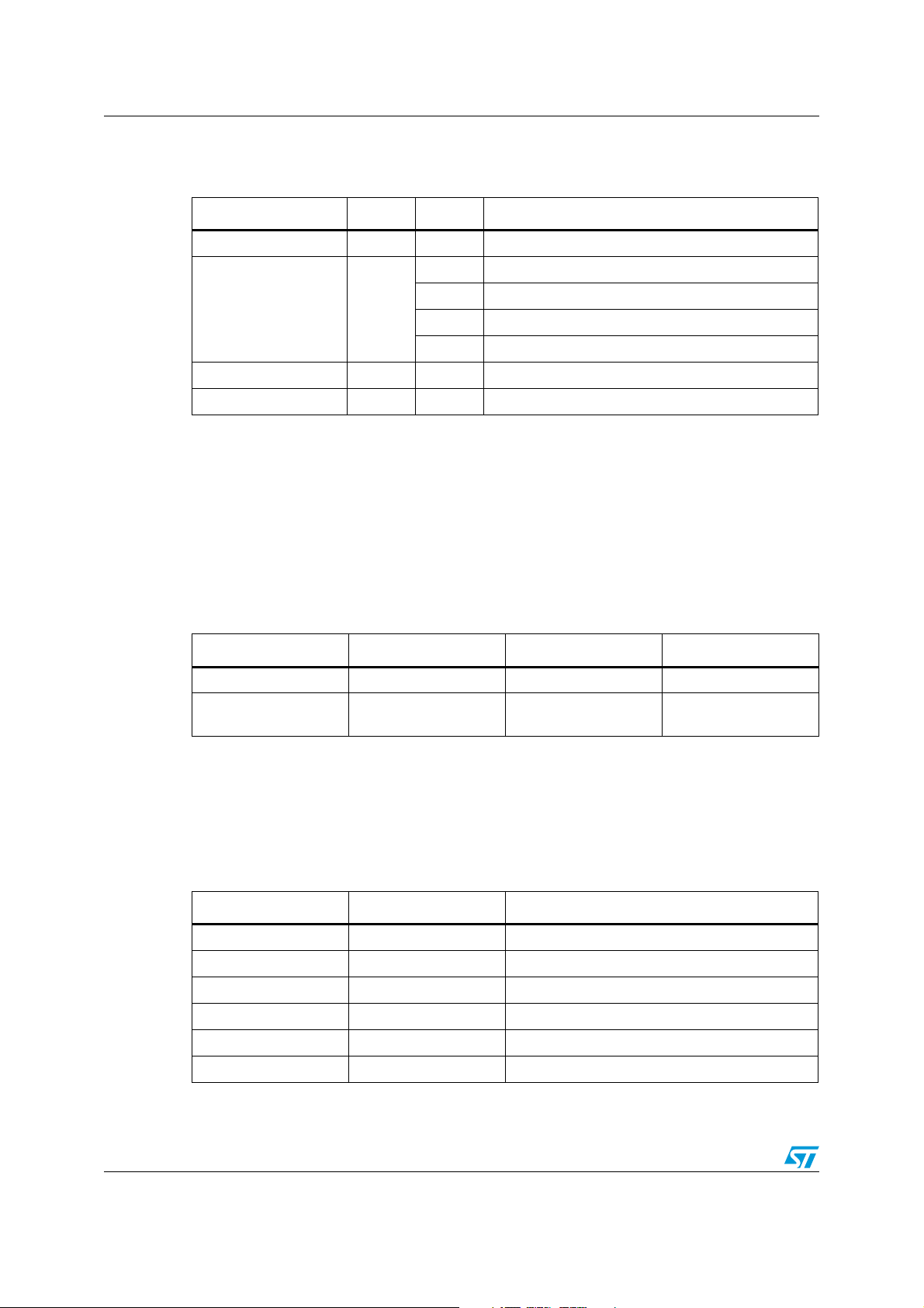
Access rights to the different memory fields are given in Ta bl e 2 .
Table 2. Access rights to memory fields
Operation
R e a d Ye s Ye s Ye s Ye s
Write Yes No Yes Yes
Lock Yes
User memory
area
For more details on the protection system, refer to the corresponding STMicroelectronics
datasheet.
1.1 User memory area
The user memory stores NDEF messages. This area can be write-protected by the user.
The user memory size depends on ISO/IEC 15693 contactless tag, as shown in Ta bl e 3 .
Table 3. ST ISO/IEC 15693 memory size
User memory
size
LRI1K LRI2K LRIS2K LRIS64K M24LR04E-R M24LR16E-R M24LR64E-R
kbit 2 kbits 2 kbits 64 kbits 2 kbits 16 kbits 64 kbits
1
128 bytes 256 bytes 256 bytes 8192 bytes 512 bytes 2048 bytes 8192 bytes
System area
UID DSFID and AFI
Locked by IC
manufacturer
Protection
system
Ye s N A
First RF block 0 0 0 0 0 0 0
Last RF block 31 63 63 2047 127 511 2047
NDEF memory
size
1. NDEF memory size includes User area and CC field memory area.
2. If NDEF message size exceeds 2040 bytes, bit 2 of CC3 shall be set (see Chapter 2.2: Capability container field).
128 bytes
(1)
256 bytes
(1)
256 bytes
(1)
8192 bytes
(1) (2)
512 bytes
(1)
2048 bytes
(1) (2)
8192 bytes
(1) (2)
Note: M24LR64E-R and M24LR16E-R have a specific format for read and write commands. Their
block number is coded on two bytes instead of one. For more details, refer to LRIS64K,
M24LR16E-R and M24LR64E-R datasheets.
6/37 Doc ID 018867 Rev 2
Page 7
AN3408 Memory organization for STMicroelectronics ISO/IEC 15693 products
1.2 DSFID and AFI system area
For more details on DSFID and AFI system area, please refer to the corresponding
STMicroelectronics datasheet.
1.3 Unique identifier
The unique identifier (UID) is an 8-byte field used to identify an IC. The UID is defined by the
IC manufacturer and is write-protected.
The UID bytes are given in Ta bl e 4 . The first byte value is fixed to 0xE0, and the second byte
value contains the IC manufacturer code.
Table 4. UID field description
UID 7 UID 6 UID 5 UID 4-0
0xE0 IC manufacturer code IC product code
Contactless tag unique
number
Note: The IC manufacturer code of STMicroelectronics is 0x02 on 8 bits (refer to [15693-3] – on
page 1).
Table 5. IC product code for ISO15639 STMicroelectronics products
UID 5
(1 byte)
1. M24LR64-R and LRIS64k have an extended addressing mode; refer to product datasheet.
LRI1K LRI2K LRIS2K
LRIS64
(1)
K
M24LR64-
(1)
R
M24LR04
E-R
M24LR64
E-R
M24LR16
E-R
0b010000xx 0b001000xx 0b001010xx 0x44 0x2C 0x2C 0x2C 0x4E
1.4 Protection system
The user memory area of ISO/IEC 15693 STMicroelectronics products can be writeprotected. The granularity of the protection can be either 4 bytes or 128 bytes as defined in
Ta bl e 6 below.
Table 6. ST ISO/IEC 15693 sector size
LRI1K LRI2K LRIS2K LRIS64K M24LR4E-R
M24LR16E-RM24LR64
E-R
Memory block
size
4 bytes 128 bytes
For more details on the protection system, please refer to the corresponding
STMicroelectronics datasheet.
● The LRIS64K and M24LRxx memory write-protected granularity is the sector.
● The LRI1K, LRI2K and LRIS2K memory write-protected granularity is the block.
Doc ID 018867 Rev 2 7/37
Page 8
NDEF data AN3408
2 NDEF data
NDEF, which stands for NFC data exchange, is a data format defined by the NFC forum.
This format defines a message encapsulation format to exchange information between a
reader and a contactless tag.
NDEF can be used to exchange different types of information such as text, URI and others.
This chapter details NDEF for the following types of information:
● text
● URI
● vCard, which is a virtual business card
● Bluetooth, that allows to carry out the pairing between two bluetooth devices.
2.1 Overview
NDEF data is composed of:
● Capability container
● TLV field, which includes the NDEF message.
The TLV field is located after the CC field. The size of a TLV field is computed according to
the CC2 byte value.
2.2 Capability container field
The Capability container field (CC field) is a 4-byte field that contains an identification value
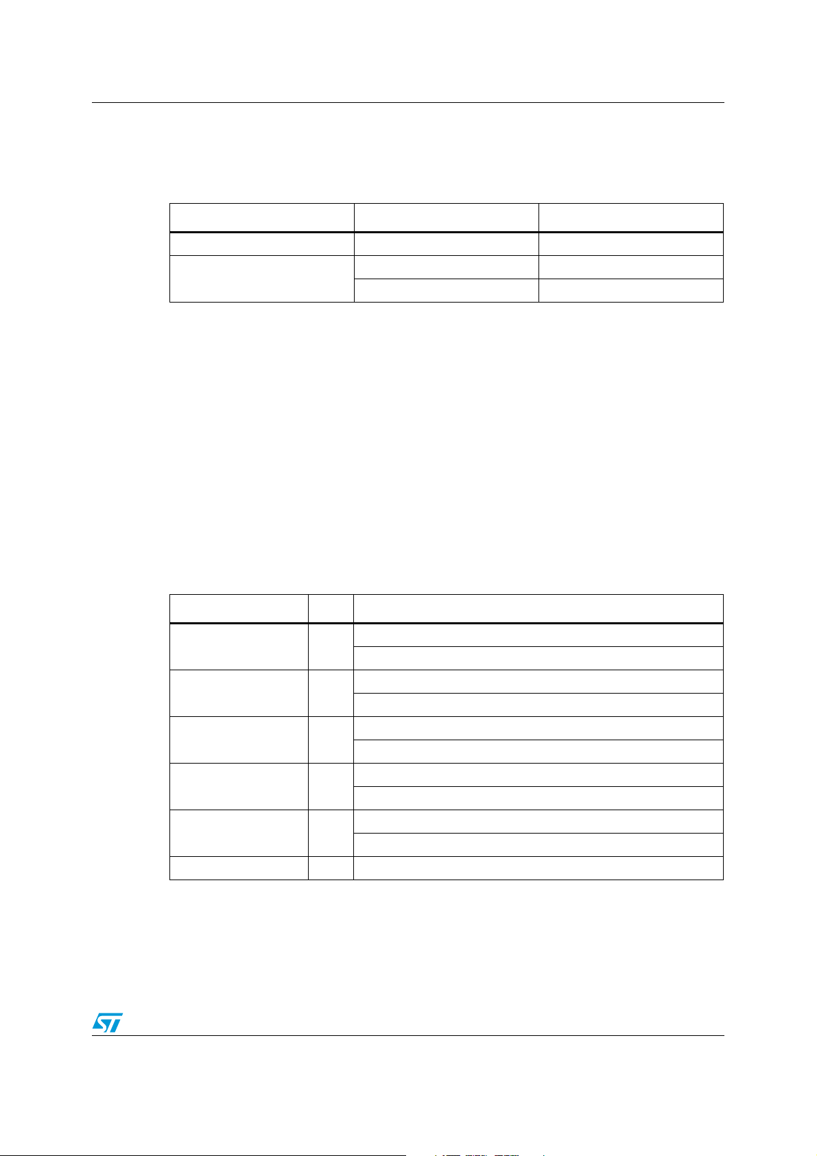
used to store an NDEF message. The signification of each byte is explained in Tab l e 7.
Table 7. Capability container field description
Byte name
CC0 0 0xE1 7:0 NDEF message is present into memory (called magic number)
CC1 1 0xXX
CC2 2 0xXX 7:0 Memory size of data field and CC field in bytes (= CC2 * 8)
CC3 3 0x0X
number
Byte
Value Bit Function
7:6 Major version number
5:4 Minor version number
3:2 Read access condition
1:0 Write access condition
7:3 RFU
2
1RFU
0
1: the IC memory size exceeds 2040 bytes (CC2 overflow)
0: the IC memory size is only defined by CC2 value
1: IC supports ReadMultipleBlocks Command
0: IC does not support ReadMultipleBlocks Command
(1)
8/37 Doc ID 018867 Rev 2
Page 9
AN3408 NDEF data
1. If bit number 2 of CC3 is set, the memory size exceeds 2040 bytes (CC2 overflow). The real memory size can be obtained
with the GetSystemInformation command. For more information about the GetSystemInformation command, refer to the
corresponding STMicroelectronics datasheet.
Read access condition values defined by bit 3 and bit 4 of CC1 byte are described in
Ta bl e 8 .
Table 8. Read access condition
Read access condition value Description
0b00 Free read access
0b01 RFU
0b10 RFU
0b11 RFU
Write access condition values defined by bit 0 and bit 1 of CC1 byte are described in
Ta bl e 9 . Write access condition values depend on the product. For more details, refer to the
corresponding STMicroelectronics datasheet.
Table 9. Write access condition
Write access
condition value
Description LRI1k, LRI2k
LRIS2k, LRIS64k,
0b00 Free write access Yes Yes
0b01 RFU No No
0b10
Write password access (data can be
written after sending a password)
No Yes
0b11 No write access Yes Yes
Note: Bit 2 and bit 3 of CC1 byte (read access values) shall be reset to 0b00 value.
The user shall set the write protection bit according to bit 0 and bit 1 of CC1 byte. For more
details, refer to the definition of the lock command in the corresponding STMicroelectronics
datasheet.
M24LR64-R
Doc ID 018867 Rev 2 9/37
Page 10
NDEF data AN3408
Example 1
Table 10. CC field example
Byte name Value Bit Function
CC0 0xE1 7:0 Magic number
7:6 Major version number: 0b01
5:4 Minor version number: 0b00
CC1 0x40
3:2 Read access condition: 0b00 (free read access)
1:0 Write access condition: 0b00 (free write access)
CC2 0x10 7:0 Data field and CC field size = 16*8 = 128 bytes
CC3 0x00 7:0 IC does not support Read multiple block
2.3 NDEF message using TLV format
A TLV format is a generic data structure used to embed information and to store NDEF
messages. The TLV format is composed of three fields:
● Type field (T)
● Length field (L)
● Value field (V): contained user message.
Table 11. TLV format description
Length (bytes) 1 1 or 3L field value
Data description
For more information on the TLV format, refer to [TAG-2] NFC forum – on page 1.
2.3.1 T field values
Ta bl e 1 2 below lists the T field values as defined by the NFC forum.
Table 12. T field values and description
TLV block name T field value Description
NULL TLV 0x00 Used to padding.
Lock control TLV 0x01 It defines details of the lock bits.
Memory control TLV 0x02 It identifies reserved memory areas.
NDEF message TLV 0x03 It contains NDEF message.
Proprietary TLV 0xFD Tag proprietary information.
Terminator TLV 0xFE Last TLV block in the data area.
T field L field V field
Type of TLV block,
see Ta bl e 12
Number of bytes of
V field
Data
10/37 Doc ID 018867 Rev 2
Page 11
AN3408 NDEF data
2.3.2 L field format
The L field can be either coded on 1 or 3 bytes, as shown in Ta bl e 1 3.
Table 13. L field byte format
Byte format Byte number Value
1 1 0x00 to 0xFE
3
1. The 0xFF FFFF value is the concatenation of the bytes 0xFF and 0xFFFF.
2.3.3 V field: NDEF message
The V field is composed of a record head byte, the NDEF message and TLV terminator. The
record head byte is described in a): Record head byte.
An application example is given to illustrate a TLV field: it is a URL, as specified in the “URI
Record Type Definition” document (NFC forum). see Chapter 4.2: URI record.
a) Record head byte
An NDEF message can contain 1 or more NDEF records. The record head byte gives some
information on the current NDEF record.
The different fields of record head byte are described in Ta bl e 1 4.
Table 14. Record head byte fields description
Name Bit Function
MB (message begin) 7
10xFF
3 0x00FF to 0xFFFE
(1)
1: This record is the first of NDEF message.
0: This record is not the first of NDEF message.
ME (message end) 6
1: This record is the last of NDEF message.
0: This record is not the last of NDEF message.
1: this record is the initial or middle record chunk.
CF (chunk flag) 5
0: this record is the terminating record chunk.
SR (short record) 4
1: the payload
0: the payload
(1)
length is on one byte.
(1)
length is more than one byte.
1: ID length field is present.
IL (ID_length flag) 3
0: ID length field is omitted.
TNF 2:0 TNF indicates the structure of the type field (see Ta bl e 1 5 ).
1. Payload is NDEF message body.
b) Type name format field values
The type name format (TNF) is a 3 bits value that indicates the structure of the value of the
type field.
Doc ID 018867 Rev 2 11/37
Page 12
NDEF data AN3408
Table 15. Type name format field values
Type name format Value
Empty
0b000
NFC forum well known type 0b001
Media type as defined in RFC 2046 0b010
Absolute URI as defined in RFC 3986 0b011
NFC forum external type 0b100
Unknown 0b101
Unchanged 0b110
Reserved 0b111
Example 1
This record head defines an NDEF message which is composed of one record
(MB = ME = 1).
Table 16. Example of a record head byte structure
Record
head byte
0xD1 11010001
Type record
head byte
MB ME CF SR IL TNF
This is the first record
This is the last record
This record is the termination chunk
The payload length size in on one byte
The ID length is omitted
NFC forum well known type
For more information about the record head byte, refer to the NDEF data exchange format
(NDEF) document.
12/37 Doc ID 018867 Rev 2
Page 13

AN3408 NDEF data
2.3.4 Specific TLV field
The two following specific TLV fields only contain a T field.
a) NULL TLV
The NULL TLV can be used for padding of the data area.
Table 17. NULL TLV field description
T field L field V field
Length (bytes) 1 0 0
Description 0x00 Not present Not present
b) Terminator TLV
The terminator TLV shall be the last TLV block of the user data field.
Table 18. Terminator TLV description
T field L field V field
Length (bytes) 1 0 0
Description 0xFE Not present Not present
Doc ID 018867 Rev 2 13/37
Page 14

Storing an NDEF message in STMicroelectronics ISO15693 products AN3408
3 Storing an NDEF message in STMicroelectronics
ISO15693 products
3.1 Memory organization of LRI1K, LRI2K and LRIS2K
The storage of a generic NDEF message in LRI1K, LRI2K and LRIS2K products is
described in Ta b le 1 9 . It also includes CC field value.
Table 19. Storing an NDEF message in LRI1K, LRI2K and LRIS2K
(1)
RF block
address
0 CC0 CC1 CC2 CC3
1 NDEF Data 0 NDEF Data 1 NDEF Data 2 NDEF Data 3
2 NDEF Data 4 ...
... ...
(2)
n
1. The UID field in system area is defined and written by STMicroelectronics and is write-protected.
2. n = 31 for LRI1K, n = 63 for LRI2K and LRIS2K.
Bits [31:24] Bits [23:16] Bits [15:8] Bits [7:0]
...
3.2 Memory organization of LRIS64K and M24LRxx devices
User memory mapping is divided in 64 sectors. A sector size is 128 bytes.
Table 20. Storing an NDEF message in LRIS64K and M24LRxx
Sector Area Sector security status
0 1 kbit EEPROM sector 5 bits
1 1 kbit EEPROM sector 5 bits
2 1 kbit EEPROM sector 5 bits
3 1 kbit EEPROM sector 5 bits
...
(1)
n
1. n = 3 for M24LR04-R, n = 15 for M24LR16-R and n = 64 for M24LR64X-R.
1 kbit EEPROM sector 5 bits
3.2.1 Description of the first sector
The NDEF message is located in the first sector, as shown in Ta bl e 2 1 .
14/37 Doc ID 018867 Rev 2
Page 15

AN3408 Storing an NDEF message in STMicroelectronics ISO15693 products
Table 21. First sector details on M24LR64-R
Sector
RF block
address
I2C block
address
Bits [31:24] Bits [23:16] Bits [15:8] Bits [7:0]
0 0 CC0 CC1 CC2 CC3
1 4 Data 0 Data 1 Data 2 Data 3
0
2 8 Data 4 ...
... ... ...
31 124 ...
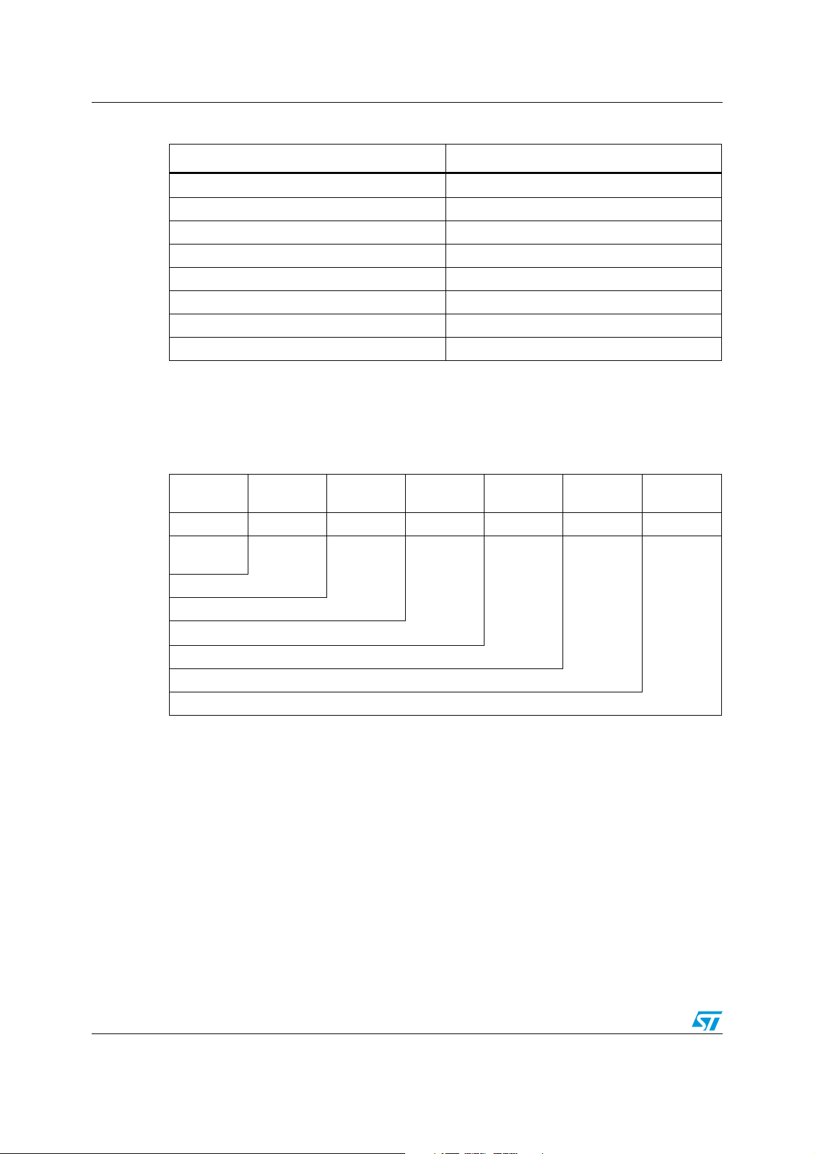
3.3 CC2 value
The CC2 byte defines the IC memory size available for a user application. It includes a CC
field and a User memory area. CC2 value = IC memory size in bytes / 8.
Table 22. CC2 value for ISO/IEC 15693 products
Product LRI1K LRI2K LRIS2K LRIS64K M24LR64X
Memory size
CC2 value
(1)
128 bytes
(1024 bits)
256 bytes
(2048 bits)
256 bytes
(2048 bits)
8192 bytes
16 = 0x10 32 = 0x20 32 = 0x20 0xFF
(64 kbits)
(2)
8192 bytes
(64 kbits)
0xFF
M24LR16E-RM24LR04E-
256 bytes
(2048 bits)
(2)
0xFF
(2)
R
64 bytes
(512 bits)
0x40
1. CC2 value is equal to memory size in bytes divided by 8. The value is expressed in hexadecimal.
2. If the contactless tag memory size exceeds the CC2 field (CC2 overflow), bit 2 of CC3 shall be set.
CC2 = 8192 / 8 = 1024d = 0x400. 0x400 value exceed 8 bits, thus CC2 of M24LR64-R is set to 0xFF (2040 bytes).
Doc ID 018867 Rev 2 15/37
Page 16

Example of NDEF record AN3408
4 Example of NDEF record
4.1 Text record
Example 1: With the text “ISO15693 as NFC tag”, the structure of the NDEF message is
described in Ta b le 2 3 .
The record header is
The value of payload is
Table 23. “ISO15693 as NFC tag” NDEF message structure
T L V as defined into NFC document
0x03 0x1A 0xD1 0x01 0x16 0x54 0x02 “en”
Ty p e
NDEF
message
TLV
Length (26 bytes)
Record head
Type length
Payload length (22 bytes)
Type (T value) for text record type
Status byte (UTF-8 and 2 bytes for language code)
Language code “en” is the ISO code for English (UTF-8 string)
UTF-8 string
Te r m in a t o r T LV
1. Refer to [TEXT] document – on page 1.
2. Payload length = status byte + Language code + UTF-8 string length = 1 + 2 + 19 = 22d.
0xD1.
0x02 + “en” + “ISO15693 as NFC tag”.
(1)
“ISO15693
as NFC tag”
(2)
Te r m in a t o r
0xFE
16/37 Doc ID 018867 Rev 2
Page 17

AN3408 Example of NDEF record
4.1.1 Memory mapping for text record type on LRI2K
Each message character is written in hexadecimal.
Table 24. LRI2K memory mapping for “ISO15693 as NFC tag” NDEF message
RF block Byte number 0 1 2 3
0 CC field 0xE1 0x10 0x20 0x00
1 User data field 0x03 0x1A 0xD1 0x01
2 0x16 0x54 0x02 0x65[e]
3 0x6E[n] 0x49[I] 0x53[S] 0x4F[O]
4 0x31|1] 0x35[5] 0x36[6] 0x39[9]
5 0x33[3] 0x20[ ] 0x61[a] 0x73[s]
6 0x20[ ] 0x4E[N] 0x46[F] 0x43[C]
7 0x20[ ] 0x74[t] 0x61[a] 0x67[g]
8 0xFE
4.2 URI record
Example 2: This example defines an NDEF message which is made of one single record.
The message is the URL “http://www.st.com”.
The record header is
In this case, the payload is
Table 25. URI record message structure
T L V as defined into URI Record Definition document
0x03 0x0B 0xD1 0x01 0x07 0x55 0x01 “st.com” 0xFE
Ty p e
NDEF
message
TLV
Length (11 bytes)
Record head
Type length
Payload length (07 bytes)
Type (U value) for URI record type
URI header identifier (http://www.)
0xD1.
0x01 and “st.com”.
(2)
NDEF data
(1)
Terminator
URI body Identifier in UTF-8 string
Te r m in a t o r T LV
1. Refer to [URI] document – on page 1.
2. Payload length = URI identifier + UTF-8 string length = 1 + 6 = 7d.
Doc ID 018867 Rev 2 17/37
Page 18

Example of NDEF record AN3408
4.2.1 Memory mapping for URI record message on LRI2K
Table 26. LRI2K memory mapping for URI record message “http://www.st.com”
RF block Byte number 0 1 2 3
0 CC field 0xE1 0x40 0x20 0x01
1 User data field 0x03 0x0B 0xD1 0x01
2 0x07 0x55 0x01 0x73[s]
3 0x74[t] 0x2E[.] 0x63[c] 0x6F[o]
40x6D[m]0xFE
4.3 Smart poster record
The smart poster record can be composed of one or more NDEF records, and one of these
records can be an "action":
● the Title record
● the URI record
● the Action record
● the Icon record
● the Size record
● the Type record
4.3.1 Title record
The title record is a text record. For more details, please refer to Section 4.1: Text record.
4.3.2 URI record
For more details on URI record, please refer to Section 4.2: URI record.
4.3.3 Action record
The action record defines a local action of the previous record. It can be, for example,
launching a web browser or sending an SMS.
The "smart poster record type definition" specification defines the available actions. Those
actions are listed in Ta bl e 2 7 below.
Table 27. List of available actions
Value Action
0x00 Do the action (send the SMS, launch the browser, make the telephone call)
0x01
0x02
0x3 to 0xFF RFU
Save for later (store the SMS in INBOX, put the URI in a bookmark, save
the telephone number in contacts)
Open for editing (open an SMS in the SMS editor, open the URI in a URI
editor, open the telephone number for editing)
18/37 Doc ID 018867 Rev 2
Page 19

AN3408 Example of NDEF record
Its type value is the three ASCII characters 'act'.
4.3.4 Icon record
The icon record contains an image (bmp or jpg) or a media type (such as an mpeg file).
4.3.5 Size record
The size record is coded on 4 bytes and defines the number of bytes. Its type value is the
ASCII character 's'.
4.3.6 Type record
The type record is UTF-8 string that describes a MIME type. Its type value is the ASCII
character 't'.
4.3.7 Example of a smart poster record composed of a Title and a URI
Table 28. Smart poster record with a Title and a URI
Ty p e
NDEF
message
TLV
Number of bytes of the NDEF message
Smart poster record
URL record
Text record
NDEF message
0x03 0x24 Smart poster record URL record Text record
Ta bl e 2 9 below details the smart poster record.
Table 29. NDEF message
0xD1 0x02 0x1F 0x5370
Record header
Record type length
Length of the smart poster
Record type 'Sp'
Doc ID 018867 Rev 2 19/37
Page 20

Example of NDEF record AN3408
Ta bl e 3 0 below details the record header of the smart poster record.
Table 30. Record header = 0xD1
This is the first
record
This is the last record
This record is the terminating record chunk
The payload length is on one byte
ID length field is omitted
Indicates the structure of the type field (see Ta b le 1 5)
MB ME CF SR IL TNF
1 10100b001
Ta bl e 3 1 below details the URI record.
Table 31. URI record
0x91 0x01 0x07 0x55 0x01 0x73 74 2e 63 6F 6D
Record header
Record type length
Payload length
Record type 'U'
Abbreviation: "http://www."
URI: st.com
Ta bl e 3 2 below details the text record.
Table 32. Text record
Record header
Record type length
Payload length
Record type 'T'
Language "en"
Carrier data reference length
Text "Welcome to ST"
0x51 0x01 0x10 0x54 0x02 0x656E
(1)
1. (1)57 65 6C 63 6F 6D 65 20 74 6F 20 53 54
20/37 Doc ID 018867 Rev 2
Page 21

AN3408 Example of NDEF record
4.3.8 Memory mapping of the smart poster record
Table 33. Memory mapping of the smart poster record
RF block 0 1 2 3
0x00 CC field 0xE1 0x40 0xFF 0x03
0x01 User data field 0x03 0x24 0xD1 0x02
0x02 0x1F 0x53 0x70 0x91
0x03 0x01 0x07 0x55 0x01
0x04 0x73 0x74 0x2E 0x63
0x05 0x6F 0x6D 0x51 0x01
0x06 0x10 0x54 0x02 0x65
0x07 0x6E 0x57 0x65 0x6C
0x08 0x63 0x6F 0x6D 0x65
0x09 0x20 0x74 0x6F 0x20
0x0A 0x53 0x54 0xFE
4.4 vCard record
The vCard is a file format standard for electronic business cards. vCard can contain name
and address information, phone numbers, e-mail addresses, URLs, logos, photographs, and
audio clips.
Table 34. vCard information
0x03 0xFF 01 BC 0xC2 0x0C 0x00 00 01 AA
(1)
Vcf file
Ty p e
NDEF
message
TLV
Number of bytes of the NDEF
message
Record header
Type length
Payload length
Type: text/x-vCard
Vcf file
1. 0x74 65 78 74 2F 78 2D 76 43 61 72 64
Doc ID 018867 Rev 2 21/37
Page 22

Example of NDEF record AN3408
The following is an example of a vCard file containing information for one person:
BEGIN:VCARD
VERSION:2.1
N:Gump;Forrest
FN: Mr. john doe
ORG: MMS
TITLE: application field engineer
TEL;WORK;VOICE:(111) 555 5453
TEL;WORK;FAX:(404) 555 6463
ADR;WORK;PREF;ENCODING=QUOTED-PRINTABLE:;;coq;Rousset;bouches du
rhones;131006;FRANCE LABEL;WORK;PREF;ENCODING=QUOTEDPRINTABLE:coq=0D=0A=131006 Rousset=0D=0A=FRANCE
URL;WORK:www.st.com EMAIL;PREF;INTERNET:john.doe@st.com
REV:20120417T121053Z
END:VCARD
Table 35. Record header = 0xC2
MB ME CF SR IL TNF
110000b010
This is the first
record
This is the last record
This record is the terminating record chunk
The payload length is on four bytes
ID length field is omitted
Indicates the structure of the type field (see Ta b le 1 5)
4.5 Bluetooth record
The Bluetooth record was defined to simplify the pairing between a host and a Bluetooth
device. The host shall know the Bluetooth address to initialize the communication with the
Bluetooth device. The NDEF message contains the information required on the Bluetooth
device (its address, name, class…) to identify it and to promptly initialize a communication
between the host and the Bluetooth device. For example, the host is an NFC mobile phone
and the Bluetooth device is a headset. The contactless tag that contains the NDEF
message, thus the Bluetooth record, is on the headset. The NFC mobile phone will first read
the NDEF message and then initialize the Bluetooth communication with the headset.
The Bluetooth record is defined in the NFC forum application document and provides the
required information to carry out the pairing between the host and the Bluetooth device.
The Bluetooth record is composed of three records, as shown in the following table.
22/37 Doc ID 018867 Rev 2
Page 23

AN3408 Example of NDEF record
Table 36. Bluetooth record
Handover select record Alternative carrier record
Defines the version
Defines the usable carrier frequency
Defines the Bluetooth configuration parameters
Those records are detailed inTa b le 3 7 . The three records are appended together in the
contactless tag memory.
Table 37. Handover select record
Record header
Record type length
Payload length
Record type 'Hs'
Version number 1.2
0x91 0x02 0x0A 0x48 73 0x12
Ta bl e 3 8 below details the record header 0x91. For more details about the record header
meaning, refer to a): Record head byte.
Table 38. Record header = 0x91
Bluetooth carrier
configuration record
MB ME CF SR IL TNF
100100b001
This is the first
record
This isn't the last record
This record is the terminating record chunk
The payload length is on one byte
ID length field is omitted
Indicates the structure of the type field (see Ta b le 1 5)
Doc ID 018867 Rev 2 23/37
Page 24

Example of NDEF record AN3408
Table 39. Alternative carrier record
0xD1 0x02 0x04 0x61 63 0x03 0x01 0x30 0x00
Record header
Record type length
Payload length
Record type 'ac'
Carrier flags CPS = 3 "unknown"
Carrier data reference length
Carrier data reference "0"
Auxiliary data reference count: 0
Ta bl e 4 0 below details the record header 0xD1. For more details about the record header
meaning, refer to a): Record head byte.
Table 40. Record header = 0xD1
This is the first record
This is the last record
MB ME CF SR IL TNF
1 10100b001
This record is the terminating record chunk
The payload length is on one byte
ID length field is omitted
Indicates the structure of the type field (see Ta b le 1 5)
24/37 Doc ID 018867 Rev 2
Page 25

AN3408 Example of NDEF record
Table 41. Bluetooth carrier configuration record
0x5A 0x20 0x1F 0x01
(1)
0x30 0x1F 00
(2)
Record
header
Record type
length
Payload length
Payload Id length
Record type
'application/vnd.bluetooth.ep.oob'
Payload ID: '0'
Bluetooth OOB Data length
Bluetooth device address: 01:bf:88:80:07:03
EIR data length
EIR data type
Class of device:
0x04: Service class = Rendering
0x06: Major Device class = Imaging
0x80: Minor Device class = Printer
0x04 0x0D
(3)
0x05 0x03
(4)
0x0B 0x09
(5)
EIR data length
EIR data type
16-bit Service Class UUID list
EIR data length
EIR data type
Bluetooth local name: DeviceName
1. 0x61 70 70 6C 69 63 61 74 69 6F 6E 2F 76 6E 64 2E 62 6C 75 65 74 6F 6F 74 68 2E 65 70
2. 0x 03 07 80 88 BF 01
3. 0x 80 06 04
4. 0x18 11 23 11
5. 0x 44 65 79 69 63 65 4E
Doc ID 018867 Rev 2 25/37
Page 26

Example of NDEF record AN3408
Ta bl e 4 2 below details the record header 0x5A. For more details about the record header
meaning, refer to a): Record head byte.
Table 42. Record header = 0x5A
This isn't the first
record
This is the last record
This record is the terminating record chunk
The payload length is on one byte
ID length field is omitted
Indicates the structure of the type field (see Ta b le 1 5)
MB ME CF SR IL TNF
010110b010
4.5.1 Memory mapping of an M24LR64E-R EEPROM
Table 43. Memory mapping of an M24LR64E-R EEPROM
RF block 0 1 2 3
0x00 CC field 0xE1 0x40 0xFF 0x03
0x01 User data field 0x91 0x02 0x0A 0x48
0x02 0x73 0x12 0xD1 0x02
0x03 0x04 0x61 0x63 0x03
0x04 0x01 0x30 0x00 0x5A
0x05 0x20 0x1F 0x01 0x61
0x06 0x70 0x70 0x6C 0x69
0x07 0x63 0x61 0x74 0x69
0x08 0x6F 0x6E 0x2F 0x76
0x09 0x6E 0x64 0x2E 0x62
0x0A 0x6C 0x75 0x65 0x74
0x0B 0x68 0x2E 0x65 0x70
0x0C 0x30 0x1F 0x00 0x03
0x0D 0x07 0x80 0x88 0xBF
0x0E 0x01 0x04 0x0D 0xB0
0x0F 0x06 0x04 0x05 0x03
0x10 0x18 0x11 0x23 0x11
0x11 0x0B 0x09 0x44 0x65
0x12 0x79 0x69 0x63 0x65
0x13 0x4E 0xFE
26/37 Doc ID 018867 Rev 2
Page 27

AN3408 Example of NDEF record
4.5.2 Simplified Bluetooth record for a single carrier wave
The simplified Bluetooth record will propose one alternative carrier. In this case, the NDEF
message will contain only one record: the Bluetooth OOB record.
Table 44. Simplified Bluetooth record for a single carrier wave
0xD2 0x20 0x21
Record
header
Record type
length
Payload length
Record type
'application/vnd.bluetooth.ep.oob'
OOB optional data length
Bluetooth device address: 01:bf:88:80:07:03
EIR data length
EIR data type
0x21
(1)
00
(2)
0x0D 0x09
(3)
0x04 0x0D
(4)
0x05 0x03
(5)
Bluetooth local name: DeviceName
EIR data length
EIR data type
Class of Device:
0x20: Service class = Audio
0x04: Major Device class = Audio/Video
0x04: Minor Device class = Wearable headset device
EIR data length
EIR data type
16-bit Service Class UUID list
1. 0x61 70 70 6C 69 63 61 74 69 6F 6E 2F 76 6E 64 2E 62 6C 75 65 74 6F 6F 74 68 2E 65 70
2. 0x 03 07 80 88 BF 01
3. 0x 48 65 61 64 53 65 74 20 4E 61 6D 65
4. 0x 04 04 20
5. 0x1E 11 0B 11
Doc ID 018867 Rev 2 27/37
Page 28

Example of NDEF record AN3408
Ta bl e 4 5 below details the record header 0xD2. For more details about the record header
meaning, refer to a): Record head byte.
Table 45. Record header = 0xD2
MB ME CF SR IL TNF
110110b010
This is the first
record
This is the last record
This record is the terminating record chunk
The payload length is on one byte
ID length field is omitted
Indicates the structure of the type field (see Ta b le 1 5)
4.5.3 Memory mapping of an M24LR64E-R EEPROM
Table 46. Memory mapping of an M24LR64E-R EEPROM
RF block 0 1 2 3
0x00 CC field 0xE1 0x40 0xFF 0x03
0x01 User data field 0xD2 0x20 0x21 0x61
0x02 0x70 0x70 0x6C 0x69
0x03 0x63 0x61 0x74 0x69
0x04 0x6F 0x6E 0x2F 0x76
0x05 0x6E 0x64 0x2E 0x62
0x06 0x6C 0x75 0x65 0x74
0x07 0x68 0x2E 0x65 0x70
0x08 0x21 0x00 0x03 0x80
0x09 0x88 0xBF 0x01 0x0d
0x0A 0x09 0x48 0x65 0x61
0x0B 0x64 0x53 0x65 0x74
0x0C 0x20 0x4E 0x61 0x6D
0x0D 0x65 0x04 0x0D 0x04
0x0E 0x04 0x20 0x05 0x03
0x0F 0x1E 0x11 0x0B 0x11
0x10 0xFE
28/37 Doc ID 018867 Rev 2
Page 29

AN3408 User application flow charts
5 User application flow charts
The following flow charts give an example of algorithms that allow to identify, read or write
an NDEF message contained inside ISO15693 contactless tag.
The ISO15693 commands are used. Refer to ISO/IEC 15693-3 description.
The card identification procedure checks the ISO/IEC 15693 specification compatibility with
the contactless tag present in the field.
5.1 ISO/IEC 15693 contactless tag identification flow chart
The following graph is a procedure to identify a contactless tag.
Figure 1. ISO/IEC 15693 contactless tag identification flow chart
Start
Send Inventory command
UID7 = 0xE0
Yes
UID6 = 0x02
Yes
Read Block 0
Block 0 = 0x00 00 00 00
Yes
Card identification
procedure for
black card
No : The contactless tag is not an ISO15693
No : the contactless tag
is not an STM product
No
NDEF
detection
procedure
End
AI18889
1. Inventory is a command defined in IEC/ISO 15693 specification or STM products datasheet.
Doc ID 018867 Rev 2 29/37
Page 30

User application flow charts AN3408
Start
Read CC (block 0)
CC byte0 = 0xE1 &
CC byte1 = right version
No
Yes : NDEF data detected
AI18890
Read Block i
Is an NDEF message
(byte 0 = 0x03) ?
No
Yes
End
Block i = Block i + 1
Block i = block 2
All blocks already read
according to NDEF length?
Yes
No
Read Block 1
5.2 Reading an NDEF message in an ISO/IEC 15693 contactless
tag
This sequence defines a user algorithm to detect an NDEF message writing into a
contactless tag memory.
Figure 2. NDEF message detection procedure
30/37 Doc ID 018867 Rev 2
Page 31

AN3408 User application flow charts
START
Write NDEF field to 0
Write NDEF message
Write NDEF field according to the length of the NDEF message
END
MS30702
5.3 WRITING an NDEF message in an ISO/IEC 15693 contactless
tag
This sequence defines a user algorithm to write an NDEF message into a contactless tag
memory.
Figure 3. Writing an NDEF message into a contactless tag memory
5.4 Identifying a blank card ISO/IEC 15693 contactless tag
This procedure identifies an ISO/IEC 15693 STMicroelectronics product and obtains
information on its memory layout. This information is extracted from the contactless tag
response to a GetSystemInformation command.
Doc ID 018867 Rev 2 31/37
Page 32

User application flow charts AN3408
Start
Send GetSystemInformation command (1)
ICreference = ISO15693 STM
product ?
No : The contactless tag is not a STM product
Yes
AI18891
End
Get memory size information
Figure 4. Identifying a blank card ISO/IEC 15693 contactless tag
1. GetSystemInformation is a command defined in IEC/ISO 15693 specification or STM products datasheet.
Information on the contactless tag response of GetSystemInformation command is given in
Ta bl e 4 7.
LRI1K LRI2K LRIS2K LRIS64K M24LR64-R
0b010000xx 0b001000xx 0b001010xx 010001xxb 0b001011xx
(1)
(2)
0x03 0x03 0x03 0x03 0x03
0x1F 0x3F 0x3F 0x07FF 0x07FF
Table 47. Contactless tag response of GetSystemInformation command
IC reference (1 byte)
Block size (bytes)
Memory size (bytes)
1. Block size = 0x03 means that the number of bytes of the block is 4 bytes.
2. The number of blocks of a contactless tag is Memory size value +1.
32/37 Doc ID 018867 Rev 2
Page 33

AN3408 User application flow charts
Start
Is an ISO15693
contactless tag ? (1)
No
Yes
AI18892
End
Write NDEF message
Is a Blank card ? (2)
Yes
Write CC field (Block 0)
Lock CC field (3)
No
5.5 Programming an NDEF message in an ISO/IEC 15693
contactless tag
This flow chart is a procedure to write an NDEF message on a contactless tag.
Figure 5. Programming an NDEF message in an ISO/IEC 15693 contactless tag
1. Use Contactless tag identification procedure defined previously.
2. Use Blank card identification procedure defined previously.
3. The CC field can be protected by using a lock command. For more details on the lock command, please
refer to the corresponding STMicroelectronics datasheet.
Doc ID 018867 Rev 2 33/37
Page 34

Acronym and notational conventions AN3408
Appendix A Acronym and notational conventions
Table 48. List of acronyms
Acronym Definition
AFI Application Family Identifier
CC Capability Container
CF Chunk Flag
IC Integrated Circuit
IL Id_Length flag
DSFID Data Storage Format IDentifier
NDEF NFC Data Exchange Format
NFC Near Field Communication
MB Message Begin
ME Message End
MCU Microcontroller Unit
OOB
Out of band
RF Radio Frequency
RFU Reserved for Future Use
SR Short Record
TLV Type Length Value
TNF Type Name Format
UID Unique IDentifier
URI Uniform Resource Identifier
URL Uniform Resource Locator (this is a special type of an URI)
A.1 Representation of numbers
The following conventions and notations apply in this document unless otherwise stated.
Binary number representation
Binary numbers are represented by strings of digits 0 and 1 shown with the most significant
bit (MSB) on the left, the least significant bit (LSB) on the right, and a “0b” added at the
beginning.
Example: 0b11110101
34/37 Doc ID 018867 Rev 2
Page 35

AN3408 Acronym and notational conventions
Hexadecimal number representation
Hexadecimal numbers are represented by using the numbers 0 to 9 and the characters A –
F, and adding an “0x” at the beginning. The Most Significant Byte (MSB) is shown on the left
and the Least Significant Byte (LSB) on the right.
Example: 0xF5
Decimal number representation
Decimal numbers are represented as is without any trailing character.
Example: 245
Doc ID 018867 Rev 2 35/37
Page 36

Revision history AN3408
Revision history
Table 49. Document revision history
Date Revision Changes
14-June-2011 1 Initial release.
Updated Acronym section and moved it to Appendix A: Acronym and
notational conventions.
Updated Table 5.: IC product code for ISO15639 STMicroelectronics
products.
Updated Binary notations, e.g. in Ta bl e 8 , Ta bl e 9 and Ta b l e 1 0.
Updated Section 3.2: Memory organization of LRIS64K and
24-Jul-2012 2
M24LRxx devices.
Updated Table 22: CC2 value for ISO/IEC 15693 products.
Added Section 4: Example of NDEF record.
Added Section 4.3: Smart poster record to Section 4.5.3: Memory
mapping of an M24LR64E-R EEPROM.
Added Section 5.3: WRITING an NDEF message in an ISO/IEC
15693 contactless tag.
36/37 Doc ID 018867 Rev 2
Page 37

AN3408
Please Read Carefully:
Information in this document is provided solely in connection with ST products. STMicroelectronics NV and its subsidiaries (“ST”) reserve the
right to make changes, corrections, modifications or improvements, to this document, and the products and services described herein at any
time, without notice.
All ST products are sold pursuant to ST’s terms and conditions of sale.
Purchasers are solely responsible for the choice, selection and use of the ST products and services described herein, and ST assumes no
liability whatsoever relating to the choice, selection or use of the ST products and services described herein.
No license, express or implied, by estoppel or otherwise, to any intellectual property rights is granted under this document. If any part of this
document refers to any third party products or services it shall not be deemed a license grant by ST for the use of such third party products
or services, or any intellectual property contained therein or considered as a warranty covering the use in any manner whatsoever of such
third party products or services or any intellectual property contained therein.
UNLESS OTHERWISE SET FORTH IN ST’S TERMS AND CONDITIONS OF SALE ST DISCLAIMS ANY EXPRESS OR IMPLIED
WARRANTY WITH RESPECT TO THE USE AND/OR SALE OF ST PRODUCTS INCLUDING WITHOUT LIMITATION IMPLIED
WARRANTIES OF MERCHANTABILITY, FITNESS FOR A PARTICULAR PURPOSE (AND THEIR EQUIVALENTS UNDER THE LAWS
OF ANY JURISDICTION), OR INFRINGEMENT OF ANY PATENT, COPYRIGHT OR OTHER INTELLECTUAL PROPERTY RIGHT.
UNLESS EXPRESSLY APPROVED IN WRITING BY TWO AUTHORIZED ST REPRESENTATIVES, ST PRODUCTS ARE NOT
RECOMMENDED, AUTHORIZED OR WARRANTED FOR USE IN MILITARY, AIR CRAFT, SPACE, LIFE SAVING, OR LIFE SUSTAINING
APPLICATIONS, NOR IN PRODUCTS OR SYSTEMS WHERE FAILURE OR MALFUNCTION MAY RESULT IN PERSONAL INJURY,
DEATH, OR SEVERE PROPERTY OR ENVIRONMENTAL DAMAGE. ST PRODUCTS WHICH ARE NOT SPECIFIED AS "AUTOMOTIVE
GRADE" MAY ONLY BE USED IN AUTOMOTIVE APPLICATIONS AT USER’S OWN RISK.
Resale of ST products with provisions different from the statements and/or technical features set forth in this document shall immediately void
any warranty granted by ST for the ST product or service described herein and shall not create or extend in any manner whatsoever, any
liability of ST.
ST and the ST logo are trademarks or registered trademarks of ST in various countries.
Information in this document supersedes and replaces all information previously supplied.
The ST logo is a registered trademark of STMicroelectronics. All other names are the property of their respective owners.
© 2012 STMicroelectronics - All rights reserved
STMicroelectronics group of companies
Australia - Belgium - Brazil - Canada - China - Czech Republic - Finland - France - Germany - Hong Kong - India - Israel - Italy - Japan -
Malaysia - Malta - Morocco - Philippines - Singapore - Spain - Sweden - Switzerland - United Kingdom - United States of America
www.st.com
Doc ID 018867 Rev 2 37/37
 Loading...