

Page 1

AN3371
Application note
Using the hardware real-time clock (RTC)
in STM32 F0, F2, F4 and L1 series of MCUs
Introduction
A real-time clock (RTC) is a computer clock that keeps track of the current time. Although
RTCs are often used in personal computers, servers and embedded systems, they are also
present in almost any electronic device that requires accurate time keeping. Microcontrollers
supporting RTC can be used for chronometers, alarm clocks, watches, small electronic
agendas, and many other devices.
This application note describes the features of the real-time clock (RTC) controller
embedded in Ultra Low Power Medium-density, Ultra Low Power High-density, F0, F2 and
F4 series devices microcontrollers, and the steps required to configure the RTC for use with
the calendar, alarm, periodic wakeup unit, tamper detection, timestamp and calibration
applications.
Examples are provided with configuration information to enable you to quickly and correctly
configure the RTC for calendar, alarm, periodic wakeup unit, tamper detection, time stamp
and calibration applications.
Note: 1 All examples and explanations are based on the STM32L1xx, STM32F0xx, STM32F2xx and
STM32F4xx firmware libraries and reference manuals of STM32L1xx (RM0038),
STM32F0xx (RM0091), STM32F2xx (RM0033) and STM32F4xx (RM0090).
2 STM32 refers to Ultra Low Power Medium-density, Ultra Low Power High-density, F0, F2
and F4 series devices in this document.
3 Ultra Low Power Medium (ULPM) density devices are STM32L151xx and STM32L152xx
microcontrollers where the Flash memory density ranges between 64 and 128 Kbytes.
4 Ultra Low Power High (ULPH) density devices are STM32L151xx, STM32L152xx and
STM32L162xx microcontrollers where the Flash memory density is 384 Kbytes.
5 F2 series devices are STM32F205xx, STM32F207xx, STM32F215xx and STM32F217xx microcontrollers.
6 F4 series are STM32F405xx, STM32F407xx, STM32F415xx and STM32F417xx microcontrollers.
7 F0 series devices are microcontrollers.
Ta bl e 1 lists the microcontrollers and development tools concerned by this application note.
Table 1. Applicable products and tools
Type Applicable products
STM32 F0 series Entry-level Cortex™-M0 MCUs
Microcontrollers
Development tools
STM32 F2 series of high-performance MCUs
STM32 F4 series of high-performance MCUs with DSP and FPU instructions
STM32 L1 ultra-low-power 32-bit MCU series
STM3240G-EVAL, STM3220G-EVAL, STM32L152D-EVAL and STM32L152EVAL evaluation boards
May 2012 Doc ID 018624 Rev 4 1/44
www.st.com
Page 2

Contents AN3371
Contents
1 Overview of the STM32 advanced RTC . . . . . . . . . . . . . . . . . . . . . . . . . . 6
1.1 RTC calendar . . . . . . . . . . . . . . . . . . . . . . . . . . . . . . . . . . . . . . . . . . . . . . . 6
1.1.1 Initializing the calendar . . . . . . . . . . . . . . . . . . . . . . . . . . . . . . . . . . . . . . 7
1.1.2 RTC clock configuration . . . . . . . . . . . . . . . . . . . . . . . . . . . . . . . . . . . . . . 8
1.2 RTC alarms . . . . . . . . . . . . . . . . . . . . . . . . . . . . . . . . . . . . . . . . . . . . . . . 10
1.2.1 RTC alarm configuration . . . . . . . . . . . . . . . . . . . . . . . . . . . . . . . . . . . . 10
1.2.2 Alarm sub-second configuration . . . . . . . . . . . . . . . . . . . . . . . . . . . . . . 12
1.3 RTC periodic wakeup unit . . . . . . . . . . . . . . . . . . . . . . . . . . . . . . . . . . . . 14
1.3.1 Programming the Auto-wakeup unit . . . . . . . . . . . . . . . . . . . . . . . . . . . . 14
1.3.2 Maximum and minimum RTC wakeup period . . . . . . . . . . . . . . . . . . . . 15
1.4 RTC digital calibration . . . . . . . . . . . . . . . . . . . . . . . . . . . . . . . . . . . . . . . 17
1.4.1 RTC coarse calibration . . . . . . . . . . . . . . . . . . . . . . . . . . . . . . . . . . . . . 17
1.4.2 RTC smooth calibration . . . . . . . . . . . . . . . . . . . . . . . . . . . . . . . . . . . . . 18
1.5 Synchronizing the RTC . . . . . . . . . . . . . . . . . . . . . . . . . . . . . . . . . . . . . . 19
1.6 RTC reference clock detection . . . . . . . . . . . . . . . . . . . . . . . . . . . . . . . . . 20
1.7 Time-stamp function . . . . . . . . . . . . . . . . . . . . . . . . . . . . . . . . . . . . . . . . . 21
1.8 RTC tamper detection function . . . . . . . . . . . . . . . . . . . . . . . . . . . . . . . . . 22
1.8.1 Edge detection on tamper input . . . . . . . . . . . . . . . . . . . . . . . . . . . . . . . 22
1.8.2 Level detection on tamper input . . . . . . . . . . . . . . . . . . . . . . . . . . . . . . . 23
1.8.3 Active time-stamp on tamper detection event . . . . . . . . . . . . . . . . . . . . 25
1.9 Backup registers . . . . . . . . . . . . . . . . . . . . . . . . . . . . . . . . . . . . . . . . . . . . 25
1.10 RTC and low-power modes . . . . . . . . . . . . . . . . . . . . . . . . . . . . . . . . . . . 25
1.11 Alternate function RTC outputs . . . . . . . . . . . . . . . . . . . . . . . . . . . . . . . . 26
1.11.1 RTC_CALIB output . . . . . . . . . . . . . . . . . . . . . . . . . . . . . . . . . . . . . . . . 26
1.11.2 RTC_ALARM output . . . . . . . . . . . . . . . . . . . . . . . . . . . . . . . . . . . . . . . 28
1.12 RTC security aspects . . . . . . . . . . . . . . . . . . . . . . . . . . . . . . . . . . . . . . . . 29
1.12.1 RTC register write protection . . . . . . . . . . . . . . . . . . . . . . . . . . . . . . . . . 29
1.12.2 Enter/exit initialization mode . . . . . . . . . . . . . . . . . . . . . . . . . . . . . . . . . 29
1.12.3 RTC clock synchronization . . . . . . . . . . . . . . . . . . . . . . . . . . . . . . . . . . 30
2 Advanced RTC features . . . . . . . . . . . . . . . . . . . . . . . . . . . . . . . . . . . . . 31
3 RTC firmware driver API . . . . . . . . . . . . . . . . . . . . . . . . . . . . . . . . . . . . . 33
2/44 Doc ID 018624 Rev 4
Page 3

AN3371 Contents
3.1 Start with the RTC driver . . . . . . . . . . . . . . . . . . . . . . . . . . . . . . . . . . . . . 33
3.1.1 Time and date configuration . . . . . . . . . . . . . . . . . . . . . . . . . . . . . . . . . 34
3.1.2 Alarm configuration . . . . . . . . . . . . . . . . . . . . . . . . . . . . . . . . . . . . . . . . 34
3.1.3 RTC wakeup configuration . . . . . . . . . . . . . . . . . . . . . . . . . . . . . . . . . . . 34
3.1.4 Outputs configuration . . . . . . . . . . . . . . . . . . . . . . . . . . . . . . . . . . . . . . . 35
3.1.5 Digital calibration configuration . . . . . . . . . . . . . . . . . . . . . . . . . . . . . . . 35
3.1.6 TimeStamp configuration . . . . . . . . . . . . . . . . . . . . . . . . . . . . . . . . . . . . 35
3.1.7 Tamper configuration . . . . . . . . . . . . . . . . . . . . . . . . . . . . . . . . . . . . . . . 35
3.1.8 Backup data registers configuration . . . . . . . . . . . . . . . . . . . . . . . . . . . . 36
3.2 Function groups and description . . . . . . . . . . . . . . . . . . . . . . . . . . . . . . . 36
4 Application examples . . . . . . . . . . . . . . . . . . . . . . . . . . . . . . . . . . . . . . . 41
5 Revision history . . . . . . . . . . . . . . . . . . . . . . . . . . . . . . . . . . . . . . . . . . . 43
Doc ID 018624 Rev 4 3/44
Page 4

List of tables AN3371
List of tables
Table 1. Applicable products and tools . . . . . . . . . . . . . . . . . . . . . . . . . . . . . . . . . . . . . . . . . . . . . . . . 1
Table 2. Steps to initialize the calendar . . . . . . . . . . . . . . . . . . . . . . . . . . . . . . . . . . . . . . . . . . . . . . . 7
Table 3. Calendar clock equal to 1 Hz with different clock sources . . . . . . . . . . . . . . . . . . . . . . . . . . 9
Table 4. Steps to configure the alarm. . . . . . . . . . . . . . . . . . . . . . . . . . . . . . . . . . . . . . . . . . . . . . . . 11
Table 5. Alarm combinations . . . . . . . . . . . . . . . . . . . . . . . . . . . . . . . . . . . . . . . . . . . . . . . . . . . . . . 11
Table 6. Alarm sub-second mask combinations . . . . . . . . . . . . . . . . . . . . . . . . . . . . . . . . . . . . . . . . 13
Table 7. Steps to configure the Auto-wakeup unit . . . . . . . . . . . . . . . . . . . . . . . . . . . . . . . . . . . . . . 14
Table 8. Timebase/wakeup unit period resolution with clock configuration 1 . . . . . . . . . . . . . . . . . . 15
Table 9. Timebase/wakeup unit period resolution with clock configuration 2 . . . . . . . . . . . . . . . . . . 16
Table 10. Min. and max. timebase/wakeup period when RTCCLK= 32768 . . . . . . . . . . . . . . . . . . . . 17
Table 11. Time-stamp features. . . . . . . . . . . . . . . . . . . . . . . . . . . . . . . . . . . . . . . . . . . . . . . . . . . . . . 21
Table 12. Tamper features (edge detection) . . . . . . . . . . . . . . . . . . . . . . . . . . . . . . . . . . . . . . . . . . . 23
Table 13. Tamper features (level detection) . . . . . . . . . . . . . . . . . . . . . . . . . . . . . . . . . . . . . . . . . . . . 25
Table 14. RTC_CALIB output frequency versus clock source . . . . . . . . . . . . . . . . . . . . . . . . . . . . . . 27
Table 15. Advanced RTC features . . . . . . . . . . . . . . . . . . . . . . . . . . . . . . . . . . . . . . . . . . . . . . . . . . . 31
Table 16. RTC function groups. . . . . . . . . . . . . . . . . . . . . . . . . . . . . . . . . . . . . . . . . . . . . . . . . . . . . . 36
Table 17. Example descriptions . . . . . . . . . . . . . . . . . . . . . . . . . . . . . . . . . . . . . . . . . . . . . . . . . . . . . 41
Table 18. Document revision history . . . . . . . . . . . . . . . . . . . . . . . . . . . . . . . . . . . . . . . . . . . . . . . . . 43
4/44 Doc ID 018624 Rev 4
Page 5

AN3371 List of figures
List of figures
Figure 1. RTC calendar fields . . . . . . . . . . . . . . . . . . . . . . . . . . . . . . . . . . . . . . . . . . . . . . . . . . . . . . . 6
Figure 2. Example of calendar display on an LCD . . . . . . . . . . . . . . . . . . . . . . . . . . . . . . . . . . . . . . . 7
Figure 3. STM32L1xx RTC clock sources . . . . . . . . . . . . . . . . . . . . . . . . . . . . . . . . . . . . . . . . . . . . . . 8
Figure 4. STM32F2xx or STM32F4xx RTC clock sources. . . . . . . . . . . . . . . . . . . . . . . . . . . . . . . . . . 8
Figure 5. Prescalers from RTC clock source to calendar unit . . . . . . . . . . . . . . . . . . . . . . . . . . . . . . . 9
Figure 6. Alarm A fields . . . . . . . . . . . . . . . . . . . . . . . . . . . . . . . . . . . . . . . . . . . . . . . . . . . . . . . . . . . 10
Figure 7. Alarm sub-second field . . . . . . . . . . . . . . . . . . . . . . . . . . . . . . . . . . . . . . . . . . . . . . . . . . . . 12
Figure 8. Prescalers connected to the timebase/wakeup unit for configuration 1 . . . . . . . . . . . . . . . 15
Figure 9. Prescalers connected to the wakeup unit for configurations 2 and 3 . . . . . . . . . . . . . . . . . 16
Figure 10. Coarse calibration block . . . . . . . . . . . . . . . . . . . . . . . . . . . . . . . . . . . . . . . . . . . . . . . . . . . 17
Figure 11. Smooth calibration block. . . . . . . . . . . . . . . . . . . . . . . . . . . . . . . . . . . . . . . . . . . . . . . . . . . 18
Figure 12. RTC shift register . . . . . . . . . . . . . . . . . . . . . . . . . . . . . . . . . . . . . . . . . . . . . . . . . . . . . . . . 19
Figure 13. RTC reference clock detection . . . . . . . . . . . . . . . . . . . . . . . . . . . . . . . . . . . . . . . . . . . . . . 20
Figure 14. Time-stamp event procedure . . . . . . . . . . . . . . . . . . . . . . . . . . . . . . . . . . . . . . . . . . . . . . . 21
Figure 15. Tamper with edge detection . . . . . . . . . . . . . . . . . . . . . . . . . . . . . . . . . . . . . . . . . . . . . . . . 23
Figure 16. Tamper with level detection . . . . . . . . . . . . . . . . . . . . . . . . . . . . . . . . . . . . . . . . . . . . . . . . 24
Figure 17. Tamper sampling with precharge pulse . . . . . . . . . . . . . . . . . . . . . . . . . . . . . . . . . . . . . . . 24
Figure 18. RTC_CALIB clock sources . . . . . . . . . . . . . . . . . . . . . . . . . . . . . . . . . . . . . . . . . . . . . . . . . 27
Figure 19. Alarm flag routed to RTC_ALARM output. . . . . . . . . . . . . . . . . . . . . . . . . . . . . . . . . . . . . . 28
Figure 20. Periodic wakeup routed to RTC_ALARM pinout. . . . . . . . . . . . . . . . . . . . . . . . . . . . . . . . . 29
Doc ID 018624 Rev 4 5/44
Page 6
Overview of the STM32 advanced RTC AN3371
MS19524V1
AM
PM
hh mm s
ss
Week
date
Month Year
Date
RTC-DR
12h or 24h format
RTC_TR
RTC_SSR
DATE
TIME
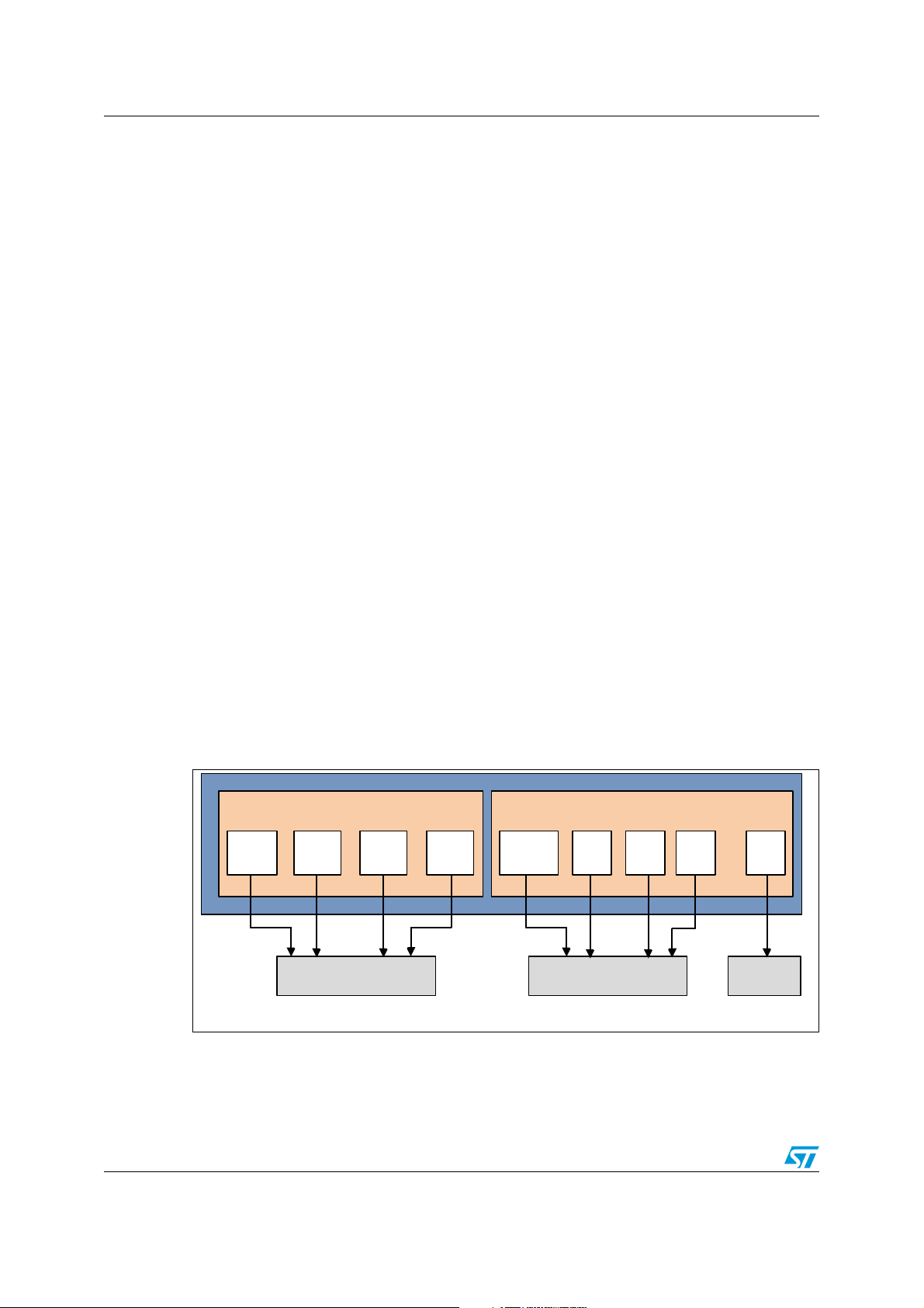
1 Overview of the STM32 advanced RTC
The real-time clock (RTC) embedded in STM32 microcontrollers acts as an independent
BCD timer/ counter. The RTC can be used to provide a full-featured calendar, alarm,
periodic wakeup unit, digital calibration, synchronization, time stamp, and advanced tamper
detection.
Refer to Table 15: Advanced RTC features for the complete list of features available on each
device.
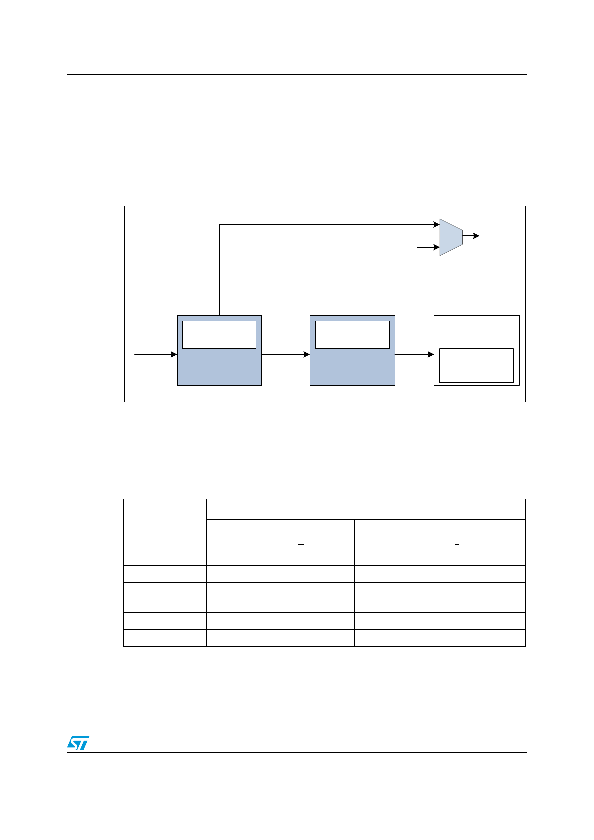
1.1 RTC calendar
A calendar keeps track of the time (hours, minutes and seconds) and date (day, week,
month, year). The STM32 RTC calendar offers several features to easily configure and
display the calendar data fields:
● Calendar with:
– sub-seconds (not programmable)
– seconds
– minutes
– hours in 12-hour or 24-hour format
– day of the week (day)
– day of the month (date)
–month
– year
● Calendar in binary-coded decimal (BCD) format
● Automatic management of 28-, 29- (leap year), 30-, and 31-day months
● Daylight saving time adjustment programmable by software
Figure 1. RTC calendar fields
1. RCT_DR, RTC_TR are RTC Date and Time registers.
2. The sub-second field is the value of the synchronous prescaler’s counter. This field is not writable.
6/44 Doc ID 018624 Rev 4
A software calendar can be a software counter (usually 32 bits long) that represents the
number of seconds. Software routines convert the counter value to hours, minutes, day of
Page 7

AN3371 Overview of the STM32 advanced RTC
11:15:28:09 PM
WED OCT 26 2011
the month, day of the week, month and year. This data can be converted to BCD format and
displayed on a standard LCD, which is useful in countries that use the 12-hour format with
an AM/PM indicator (see Figure 2). Conversion routines use significant program memory
space and are CPU-time consuming, which may be critical in certain real-time applications.
When using the STM32 RTC calendar, software conversion routines are no longer needed
because their functions are performed by hardware.
The STM32 RTC calendar is provided in BCD format. This avoids binary to BCD software
conversion routines, which use significant program memory space and a CPU-load that may
be critical in certain real-time applications.
Figure 2. Example of calendar display on an LCD
1.1.1 Initializing the calendar
Ta bl e 2 describes the steps required to correctly configure the calendar time and date.
Table 2. Steps to initialize the calendar
Step What to do How to do it Comments
Disable the RTC registers Write
1
protection
2 Enter Initialization mode
Wait for the confirmation of
3
Initialization mode (clock
synchronization)
Program the prescalers register
4
if needed
Load time and date values in
5
the shadow registers
Configure the time format (12h
6
or 24h)
7 Exit Initialization mode
Write "0xCA" and then
"0x53" into the
RTC_WPR register
Set INIT bit to ‘1’ in
RTC_ISR register
Poll INITF bit of in
RTC_ISR until it is set
RTC_PRER register:
Write first the
synchronous value and
then write the
asynchronous
Set RTC_TR and
RTC_DR registers
Set FMT bit in RTC_CR
register
Clear the INIT bit in
RTC_ISR register
RTC registers can be modified
The calendar counter is
stopped to allow update
It takes approximately 2
RTCCLK clock cycles for
medium density devices
By default, the RTC_PRER
prescalers register is initialized
to provide 1Hz to the Calendar
unit when RTCCLK = 32768Hz
FMT = 0: 24 hour/day format
FMT = 1: AM/PM hour format
The current calendar counter is
automatically loaded and the
counting restarts after 4
RTCCLK clock cycles
Enable the RTC Registers
8
Write Protection
Doc ID 018624 Rev 4 7/44
Write "0xFF" into the
RTC_WPR register
RTC Registers can no longer
be modified
Page 8
Overview of the STM32 advanced RTC AN3371
MS19525V1
HSE OSC
1-24 MHz
LSE OSC
32.768 kHz
LSI RC
37 kHz
HSE_RTC
HSE
LSE
LSI
/2, 4,
8,16
To RTC
RTCCLK
RTCSEL[1:0]
MS19526V1
LSI RC
32 kHz
LSE OSC
32.768 kHz
HSE OSC
4-26 MHz
HSE_RTC
LSI
LSE
HSE
To RTC
RTCCLK
RTCSEL[1:0]
LSI RC
32 kHz
/2 to 31
1.1.2 RTC clock configuration
RTC clock source
The RTC calendar can be driven by three clock sources LSE, LSI or HSE (see Figure 3 and
Figure 4).
Figure 3. STM32L1xx RTC clock sources
Note: RTCSEL[1:0] bits are the RCC Control/status register (RCC_CSR) [17:16] bits
Figure 4. STM32F2xx or STM32F4xx RTC clock sources
8/44 Doc ID 018624 Rev 4
How to adjust the RTC calendar clock
The RTC features several prescalers that allow delivering a 1 Hz clock to calendar unit,
regardless of the clock source.
Page 9
AN3371 Overview of the STM32 advanced RTC
Synchronous 13-bit
prescaler (default=256)
RTC
Clock
PREDIV_A
PREDIV_S
Ck_Spre
Asynchronous
prescaler
Synchronous
prescaler
Calendar unit
MS19527V1
Asynchronous 7-bit
prescaler (default = 128)
Shadow registers
(RTC_TR and
RTC_DR)
ck_spre
RTCCLK
PREDIV_A 1+()PREDIV_S 1+()×
-----------------------------------------------------------------------------------------------=
Figure 5. Prescalers from RTC clock source to calendar unit
Note: The length of the synchronous prescaler depends on the product. For this section, it is
represented on 13 bits.
The formula to calculate ck_spre is:
where:
● RTCCLK can be any clock source: HSE_RTC, LSE or LSI
● PREDIV_A can be 1,2,3,..., or 127
● PREDIV_S can be 0,1,2,..., or 8191
Ta bl e 3 shows several ways to obtain the calendar clock (ck_spre) = 1 Hz.
Table 3. Calendar clock equal to 1 Hz with different clock sources
RTCCLK
Clock source
HSE_RTC = 1MHz
LSE = 32.768 kHz
LSI = 32 kHz
LSI = 37 kHz
1. For STM32L1xx, LSI = 37 KHz, but LSI accuracy is not suitable for calendar application.
2. For STM32F2xx and STM32F4xx, LSI = 32 KHz, but LSI accuracy is not suitable for calendar application.
(1)
(2)
PREDIV_A[6:0] PREDIV_S[12:0]
124
(div125)
127
(div128)
127
(div128)
124
(div125)
Prescalers
7999
(div8000)
255
(div256)
249
(div250)
295
(div296)
ck_spre
1 Hz
1 Hz
1 Hz
1 Hz
Doc ID 018624 Rev 4 9/44
Page 10
Overview of the STM32 advanced RTC AN3371
MS19528V1
Day of week
Alarm date
AM
PM
hh mm s
12h or 24h
format
RTC_ALRMAR
Alarm time
Date
Mask2Mask3 Mask1ssMask0 Mask ss
RTC_ALRMASSR
1.2 RTC alarms
1.2.1 RTC alarm configuration
STM32 RTC embeds two alarms, alarm A and alarm B, which are similar. An alarm can be
generated at a given time or/and date programmed by the user.
The STM32 RTC provides a rich combination of alarms settings, and offers many features to
make it easy to configure and display these alarms settings.
Each alarm unit provides the following features:
● Fully programmable alarm: sub-second (this is discussed later), seconds, minutes,
hours and date fields can be independently selected or masked to provide a rich
combination of alarms.
● Ability to exit the device from low power modes when the alarm occurs.
● The alarm event can be routed to a specific output pin with configurable polarity.
● Dedicated alarm flags and interrupt.
Figure 6. Alarm A fields
10/44 Doc ID 018624 Rev 4
1. RTC_ALRMAR is an RTC register. The same fields are also available for the RTC_ALRMBR register.
2. RT_ARMASSR is an RTC register. The same field is also available for the RTC_ALRMBR register.
3. Maskx are bits in the RTC_ALRMAR register that enable/disable the RTC_ALARM fields used for alarm A
and calendar comparison. For more details, refer to Table 5.
4. Mask ss are bits in the RTC_ALRMASSR register.
An alarm consists of a register with the same length as the RTC time counter. When the
RTC time counter reaches the value programmed in the alarm register, a flag is set to
indicate that an alarm event occurred.
The STM32 RTC alarm can be configured by hardware to generate different types of
alarms. For more details, refer to Ta bl e 5.
Programming the alarm
Ta bl e 4 describes the steps required to configure alarm A.
Page 11
AN3371 Overview of the STM32 advanced RTC
Table 4. Steps to configure the alarm
Step What to do How to do it Comments
Disable the RTC registers Write
1
protection
2 Disable alarm A
Check that the RTC_ALRMAR
3
register can be accessed
4 Configure the alarm
5 Re-enable alarm A
Enable the RTC registers Write
6
protection
1. Respectively ALRBE bit for alarm B.
2. Respectively ALRBWF bit for alarm B.
3. Respectively RTC_ALRMBR register for alarm B.
4. As an example, if the alarm is configured to occur at 3:00:00 PM, the alarm will not occur even if the
calendar time is 15:00:00, because the RTC calendar is 24-hour format and the alarm is 12-hour format.
5. Respectively ALRBE bit for alarm B.
6. RTC alarm registers can only be written when the corresponding RTC alarm is disabled or during RTC
Initialization mode.
Write "0xCA" and then
"0x53" into the
RTC_WPR register
(1)
Clear ALRAE
bit in
RTC_CR register.
(2)
Poll ALRAWF
bit until
it is set in RTC_ISR.
Configure
RTC_ALRMAR
(3)
register.
(5)
Set ALRAE
bit in
RTC_CR register.
Write "0xFF" into the
RTC_WPR register
RTC registers can be modified
It takes approximately two
RTCCLK clock cycles (clock
synchronization).
The alarm hour format must be
the same
(4)
as the RTC
Calendar in RTC_ALRMAR.
RTC registers can no longer be
modified
Configuring the alarm behavior using the MSKx bits
The alarm behavior can be configured using the MSKx bits (x = 1, 2, 3, 4) of the
RTC_ALRMAR register for alarm A (RTC_ALRMBR register for alarm B).
Ta bl e 5 shows all the possible alarm settings. As an example, to configure the alarm time to
23:15:07 on Monday (assuming that the WDSEL = 1), MSKx bits must be set to 0000b.
When the WDSEL = 0, all cases are similar, except that the Alarm Mask field compares with
the day number and not the day of the week, and MSKx bits must be set to 0000b.
Table 5. Alarm combinations
MSK3 MSK2 MSK1 MSK0
0000
0001
All fields are used in alarm comparison:
Alarm occurs at 23:15:07, each Monday.
Seconds do not matter in alarm comparison
The alarm occurs every second of 23:15, each Monday.
Minutes do not matter in alarm comparison
0010
The alarm occurs at the 7th second of every minute of 23:XX, each
Monday.
0011Minutes and seconds do not matter in alarm comparison
0100Hours do not matter in alarm comparison
0101Hours and seconds do not matter in alarm comparison
Alarm behavior
Doc ID 018624 Rev 4 11/44
Page 12
Overview of the STM32 advanced RTC AN3371
MS30110V1
Alarm sub-second
AM
PM
hh mm s
12h or 24h
format
Alarm flag
Time
ss
ss
Mask ss
=
Table 5. Alarm combinations (continued)
MSK3 MSK2 MSK1 MSK0
0110Hours and minutes do not matter in alarm comparison
0111
1000
Hours, minutes and seconds do not matter in alarm comparison
The alarm is set every second, each Monday, during the whole day.
Week day (or date, if selected) do not matter in alarm comparison
Alarm occurs all days at
1001Week day and seconds do not matter in alarm comparison
1010Week day and minutes do not matter in alarm comparison
1011Week day, minutes and seconds do not matter in alarm comparison
1100Week day and hours do not matter in alarm comparison
1101Week day, hours and seconds do not matter in alarm comparison
1110Week day, hours and minutes do not matter in alarm comparison
1111Alarm occurs every second
Alarm behavior
23:15:07.
Caution: If the seconds field is selected (MSK0 bit reset in RTC_ALRMAR or RTC_ALRMBR), the
synchronous prescaler division factor PREDIV_S set in the RTC_PRER register must be at
least 3 to ensure a correct behavior.
1.2.2 Alarm sub-second configuration
The STM32 RTC unit provides programmable alarms, sub-second A and B, which are
similar. They generate alarms with a high resolution (for the second division).
The value programmed in the Alarm sub-second register is compared to the content of the
sub-second field in the calendar unit.
The sub-second field counter counts down from the value configured in the synchronous
prescaler to zero, and then reloads a value in the RTC_SPRE register.
Figure 7. Alarm sub-second field
Note: Mask ss is the most significant bit in the sub-second alarm. These are compared to the
synchronous prescaler register.
12/44 Doc ID 018624 Rev 4
Page 13

AN3371 Overview of the STM32 advanced RTC
The Alarm sub-second can be configured using the mask ss bits in the alarm sub-second
register. Table 6: Alarm sub-second mask combinations shows the configuration possibilities
for the mask register and provides an example with the following settings:
● Select LSE as the RTC clock source (for example LSE = 32768 Hz).
● Set the Asynchronous prescaler to 127.
● Set the Synchronous prescaler to 255 (the Calendar clock is equal to 1Hz).
● Set the alarm A sub-second to 255 (put 255 in the SS[14:0] field).
Table 6. Alarm sub-second mask combinations
MASKSS Alarm A sub-second behavior Example result
0
1
2
3
4
5
6
7
8
9
10
11
There is no comparison on sub-second for alarm. The alarm is
activated when the second unit is incremented.
Only the AlarmA_SS[0] bit is compared to the RTC sub-second
register RTC_SSR
Only the AlarmA_SS[1:0] bit is compared to the RTC sub-second
register RTC_SSR
Only the AlarmA_SS[2:0] bit is compared to the RTC sub-second
register RTC_SSR
Only the AlarmA_SS[3:0] bit is compared to the RTC sub-second
register RTC_SSR
Only the AlarmA_SS[4:0] bit is compared to the RTC sub-second
register RTC_SSR
Only the AlarmA_SS[5:0] bit is compared to the RTC sub-second
register RTC_SSR
Only the AlarmA_SS[6:0] bit is compared to the RTC sub-second
register RTC_SSR
Only the AlarmA_SS[7:0] bit is compared to the RTC sub-second
register RTC_SSR
Only the AlarmA_SS[8:0] bit is compared to the RTC sub-second
register RTC_SSR
Only the AlarmA_SS[9:0] bit is compared to the RTC sub-second
register RTC_SSR
Only the AlarmA_SS[10:0] bit is compared to the RTC sub-second
register RTC_SSR
The alarm is activated every
1 second
The alarm is activated every
(1/128) s
The alarm is activated every
(1/64) s
The alarm is activated every
(1/32) s
The alarm is activated every
(1/16) s
The alarm is activated every
125 ms
The alarm is activated every
250 ms
The alarm is activated every
500 ms
The alarm is activated every 1 s
The alarm is activated every 1 s
The alarm is activated every 1 s
The alarm is activated every 1 s
12
13
14
15
Only the AlarmA_SS[11:0] bit is compared to the RTC sub-second
register RTC_SSR
Only the AlarmA_SS[12:0] bit is compared to the RTC sub-second
register RTC_SSR
Only the AlarmA_SS[13:0] bit is compared to the RTC sub-second
register RTC_SSR
Only the AlarmA_SS[14:0] bit is compared to the RTC sub-second
register RTC_SSR
The alarm is activated every 1 s
The alarm is activated every 1 s
The alarm is activated every 1 s
The alarm is activated every 1 s
Note: The overflow bits in the sub-second register bit (15,16 and 17) are never compared.
Doc ID 018624 Rev 4 13/44
Page 14

Overview of the STM32 advanced RTC AN3371
1.3 RTC periodic wakeup unit
Like many STMicroelectronics microcontrollers, the STM32 provides several low power
modes to reduce the power consumption.
The STM32 features a periodic timebase and wakeup unit that can wake up the system
when the STM32 operates in low power modes. This unit is a programmable downcounting
auto-reload timer. When this counter reaches zero, a flag and an interrupt (if enabled) are
generated.
The wakeup unit has the following features:
● Programmable downcounting auto-reload timer.
● Specific flag and interrupt capable of waking up the device from low power modes.
● Wakeup alternate function output which can be routed to RTC_ALARM output (unique
pad for alarm A, alarm B or Wakeup events) with configurable polarity.
● A full set of prescalers to select the desired waiting period.
1.3.1 Programming the Auto-wakeup unit
Ta bl e 7 describes the steps required to configure the Auto-wakeup unit.
Table 7. Steps to configure the Auto-wakeup unit
Step What to do How to do it Comments
1 Disable the RTC registers Write protection
2 Disable the wakeup timer.
3
4 Program the value into the wakeup timer.
5 Select the desired clock source.
6 Re-enable the wakeup timer.
7 Enable the RTC registers Write protection
Ensure access to Wakeup auto-reload
counter and bits WUCKSEL[2:0] is allowed.
Write "0xCA" and
then "0x53" into the
RTC_WPR register
Clear WUTE bit in
RTC_CR register
Poll WUTWF until it
is set in RTC_ISR
Set WUT[15:0] in
RTC_WUTR register
Program
WUCKSEL[2:0] bits
in RTC_CR register
Set WUTE bit in
RTC_CR register
Write "0xFF" into the
RTC_WPR register
RTC registers can be
modified
It takes approximately
2 RTCCLK clock cycles
See Section 1.3.2:
Maximum and minimum
RTC wakeup period
The wakeup timer
restarts downcounting
RTC registers can no
more be modified
14/44 Doc ID 018624 Rev 4
Page 15

AN3371 Overview of the STM32 advanced RTC
MS19529V1
WUCKSEL[1:0]
RTCCLK
16-bit wakeup
auto-relaod timer
Prescaler /
2,4,8,16
RTC_WUTR
WUCKSEL[2]
Periodic
wakeup flag
1.3.2 Maximum and minimum RTC wakeup period
The wakeup unit clock is configured through the WUCKSEL[2:0] bits of RTC_CR1 register.
Three different configurations are possible:
● Configuration 1: WUCKSEL[2:0] = 0xxb for short wakeup periods
(see Periodic timebase/wakeup configuration for clock configuration 1)
● Configuration 2: WUCKSEL[2:0] = 10xb for medium wakeup periods
(see Periodic timebase/wakeup configuration for clock configuration 2)
● Configuration 3: WUCKSEL[2:0] = 11xb for long wakeup periods
(see Periodic timebase/wakeup configuration for clock configuration 3)
Periodic timebase/wakeup configuration for clock configuration 1
Figure 8 shows the prescaler connection to the timebase/wakeup unit and Ta bl e 8 gives the
timebase/wakeup clock resolutions corresponding to configuration 1.
The prescaler depends on the Wakeup clock selection:
● WUCKSEL[2:0] =000: RTCCLK/16 clock is selected
● WUCKSEL[2:0] =001: RTCCLK/8 clock is selected
● WUCKSEL[2:0] =010: RTCCLK/4 clock is selected
● WUCKSEL[2:0] =011: RTCCLK/2 clock is selected
Figure 8. Prescalers connected to the timebase/wakeup unit for configuration 1
Table 8. Timebase/wakeup unit period resolution with clock configuration 1
Wakeup period resolution
Clock source
WUCKSEL[2:0] = 000b (div16) WUCKSEL[2:0] = 011b (div2)
LSE = 32 768 Hz 488.28 µs 61.035 µs
When RTCCLK= 32768 Hz, the minimum timebase/wakeup resolution is 61.035 µs, and the
maximum resolution is 488.28 µs. As a result:
● The minimum timebase/wakeup period is (0x0001 + 1) x 61.035 µs = 122.07 µs.
The timebase/wakeup timer counter WUT[15:0] cannot be set to 0x0000 with
WUCKSEL[2:0]=011b (f
RTCCLK
/2) because this configuration is prohibited. Refer to the
STM32 reference manuals for more details.
● The maximum timebase/wakeup period is (0xFFFF+ 1) x 488.28 µs = 2 s.
Doc ID 018624 Rev 4 15/44
Page 16

Overview of the STM32 advanced RTC AN3371
MS19530V1
RTC Clock
16-bit wakeup auto-
reload timer
Asynch. 7-bit prescaler
(default=128)
Wakeup
autoreload
timer
(RTC_WUTR)
WUCKSEL[2]
Periodic
wakeup flag
Asynchronous
prescaler
(PREDIV_A)
Synchronous
prescaler
(PREDIV_S)
Synchronous 13-bit
prescaler (default=256)
Periodic timebase/wakeup configuration for clock configuration 2
Figure 9 shows the prescaler connection to the timebase/wakeup unit and Ta bl e 9 gives the
timebase/wakeup clock resolutions corresponding to configuration 2.
Figure 9. Prescalers connected to the wakeup unit for configurations 2 and 3
Table 9. Timebase/wakeup unit period resolution with clock configuration 2
Wakeup period resolution
Clock source
PREDIV_A[6:0] = div128
PREDIV_S [12:0] = div8192
PREDIV_A[6:0] = div2
PREDIV_S [12:0] = div1
(1)
LSE = 32 768 Hz 32 s 61.035 µs
1. PREDIV_A minimum value is ‘1’ on medium density devices.
When RTCCLK= 32768 Hz, the minimum resolution for configuration 2 is 61.035 µs, and the
maximum resolution is 32s.
As a result:
● The minimum timebase/wakeup period is (0x0000 + 1) x 61.035 µs = 122.07 µs.
● The maximum timebase/wakeup period is (0xFFFF+ 1) x 32 s = 131072 s (more than
36 hours).
Periodic timebase/wakeup configuration for clock configuration 3
For this configuration, the resolution is the same as for configuration 2. However, the
timebase/wakeup counter downcounts starting from 0x1FFFF to 0x00000, instead of
0xFFFF to 0x0000 for configuration 2.
When RTCCLK= 32768,
● The minimum timebase/wakeup period is:
(0x10000 + 1) x 61.035 µs = 250.06 ms
● The maximum timebase/wakeup period is:
(0x1FFFF+ 1) x 32 s = 4194304 s (more than 48 days).
16/44 Doc ID 018624 Rev 4
Page 17

AN3371 Overview of the STM32 advanced RTC
MS19531V1
RTC Clock
Asynch. 7-bit prescaler
(default=128)
Asynchronous
prescaler
Synchronous
prescaler
Synchronous 13-bit
prescaler (default=256)
Coarse
calibration
Shadow registers
(RTC_TR, RTC_DR)
Calendar
512 Hz
AFO_CALIB
Ck_Spre
Summary of timebase/wakeup period extrema
When RTCCLK= 32768 Hz, the minimum and maximum period values, depending on the
configuration, are listed in Ta bl e 1 0.
Table 10. Min. and max. timebase/wakeup period when RTCCLK= 32768
Configuration Minimum period Maximum period
1
2
3
1. These values are calculated when RTCCLK = 32768 Hz
1.4 RTC digital calibration
1.4.1 RTC coarse calibration
The digital coarse calibration can be used to compensate crystal inaccuracy by adding
(positive calibration) or masking (negative calibration) clock cycles at the output of the
asynchronous prescaler (ck_apre).
A negative calibration can be performed with a resolution of about 2 ppm, and a positive
calibration can be performed with a resolution of about 4 ppm. The maximum calibration
ranges from -63 ppm to 126 ppm.
Figure 10. Coarse calibration block
122.07 µs
2s
122.07 µs more than 36 hours
250.06 ms more than 48 days
You can calculate the clock deviation using AFO_CALIB, then update the calibration block. It
is not possible to check the calibration result, as the 512 Hz output is before the calibration
block. You can check the calibration result with certain products, as the 1 Hz CK_Spre
output is after the coarse calibration block. Refer to Table 15: Advanced RTC features.
Note: 1 The calibration settings can only be changed during initialization.
The full calibration cycle lasts 64 minutes.
The calibration is done during the first minutes (from 0 to 62 min depending on the
configuration) of the calibration cycle.
2 We recommend the use of coarse calibration for static correction only. Due to the points
listed in note 1, changing the calibration settings brings errors:
- Entering initialization mode stops the calendar and reinitializes the prescalers
- The calibration change rate must be very much smaller than the calibration window size in
order to minimize the impact of the error brought by the change on the final accuracy.
Doc ID 018624 Rev 4 17/44
Page 18

Overview of the STM32 advanced RTC AN3371
MS30112V1
RTC
Clock
Asynch. 7-bit prescaler
(default=128)
Asynchronous
prescaler
Synchronous
prescaler
Synchronous 15-bit
prescaler (default=256)
Shadow registers
(RTC_TR, RTC_DR)
Calendar
512 Hz
AFO_CALIB
Ck_Spre
Smooth
calibration
Consequently, the coarse calibration is not adequate for a dynamic calibration (such as the
compensation of the quartz variations due to external temperature changes).
3 The reference clock calibration and the coarse calibration cannot be used together.
Caution: Digital coarse calibration may not work correctly if PREDIV_A < 6.
1.4.2 RTC smooth calibration
The RTC clock frequency can be corrected using a series of small adjustments by adding or
subtracting individual RTCCLK pulses.The RTC clock can be calibrated with a resolution of
about 0.954 ppm with a range from -487.1 ppm to +488.5 ppm.
This digital smooth calibration is designed to compensate for the inaccuracy of crystal
oscillators due to temperature, crystal aging.
Figure 11. Smooth calibration block
You can compute the clock deviation using AFO_CALIB, then update the calibration block. It
is possible to check the calibration result using calibration output 512 Hz or 1 Hz for the
AFO_CALIB signal, depending on the products. Refer to Table 15: Advanced RTC features.
Smooth calibration consists of masking and adding N (configurable) 32 kHz pulses that are
well distributed in a configurable window (8 s, 16 s or 32 s).
The number of masked or added pulses is defined using CALP and CALM in the
RTC_CALR register.
By default, the calibration window is 32 seconds. It can be reduced to 8 or 16 seconds by
setting the CALW8 bit or the CALW16 bit in the RTC_CALR register:
Example 1: Setting CALM[0] to 1, CALP=0 and using 32 seconds as a calibration window
results in exactly one pulse being masked for 32 seconds.
Example 2: Setting CALM[2] to 1, CALP=0 and using 32 seconds as a calibration window
results in exactly 4 pulses being masked for 32 seconds.
Note: 1 Both CALM and CALP can be used and, in this case, an offset ranging from -511 to +512
pulses can be added for 32 seconds (calibration window).
2 When the asynchronous prescaler is less than 3, CALP cannot be set to 1.
The formula to calculate the effective calibrated frequency (FCAL), given the input frequency
(FRTCCLK), is:
F
= F
CAL
RTCCLK
x [ 1 + (CALP x 512 - CALM) / (220 + CALM - CALP x 512) ].
18/44 Doc ID 018624 Rev 4
Page 19
AN3371 Overview of the STM32 advanced RTC
MS30111V1
RTC Clock
Asynch. 7-bit prescaler
(default=128)
Asynchronous
prescaler
Synchronous
prescaler
Synchronous 15-bit
prescaler (default=256)
Shadow registers
(RTC_TR, RTC_DR)
Calendar
512 Hz
AFO_CALIB
Ck_Spre
Shift
(RTC_SHIFTER)
delay
advance
A smooth calibration can be performed on the fly so that it can be changed when the
temperature changes or if other factors are detected.
Checking the smooth calibration
The smooth calibration effect on the calendar clock (RTC Clock) can be checked by:
● Calibration using the AFO_CALIB (512 Hz or 1 Hz).
● Calibration using the sub-second alarms.
● Calibration using the Wakeup timer.
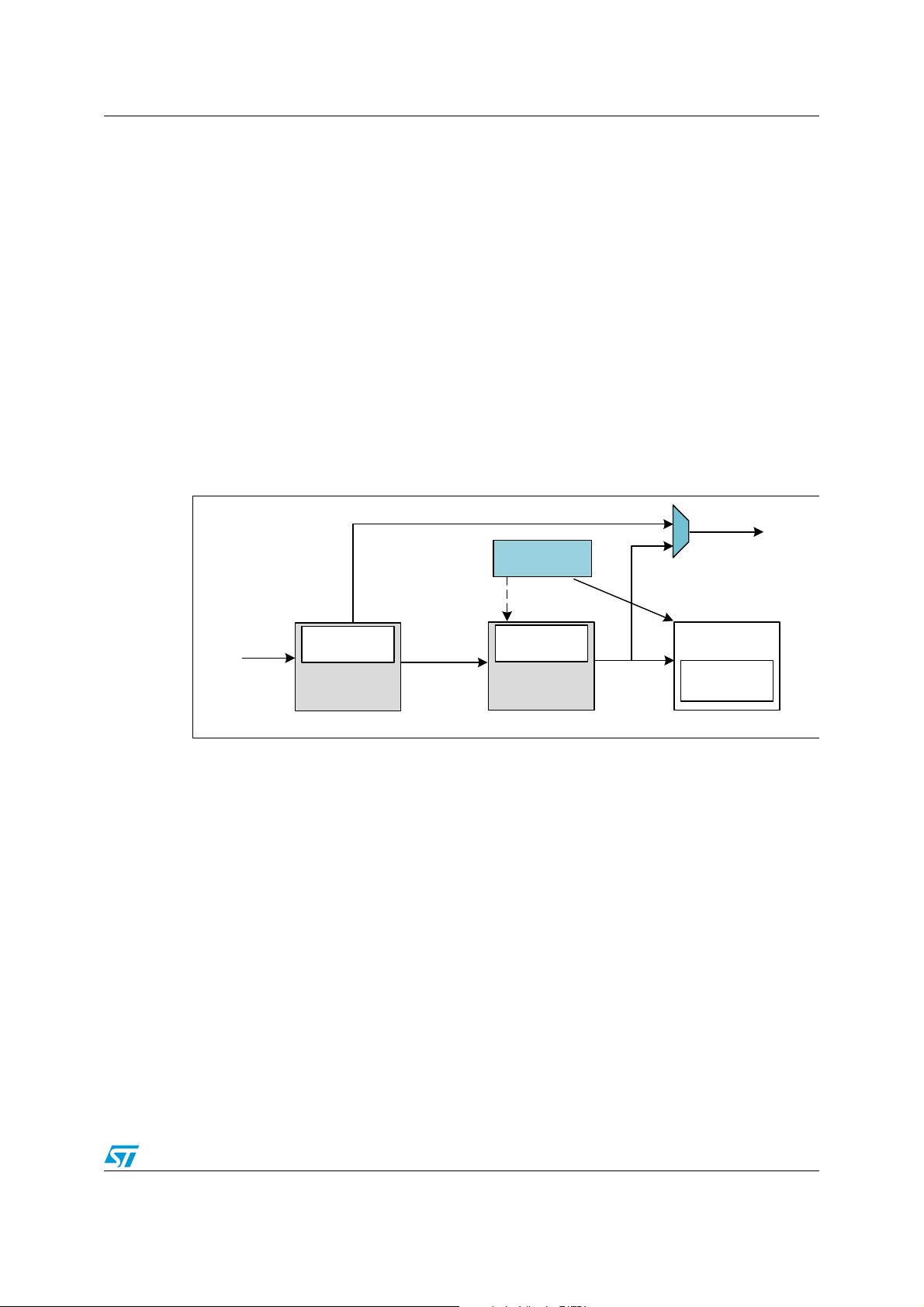
1.5 Synchronizing the RTC
The RTC calendar can be synchronized to a more precise clock, “remote clock”, using the
RTC shift feature. After reading the RTC sub-second field, a calculation of the precise offset
between the time being maintained by the remote clock and the RTC can be made. The
RTC can be adjusted by removing this offset with a fine adjustment using the shift register
control.
Figure 12. RTC shift register
It is not possible to check the “Synchronization” Shift function using the AFO_CALIB output
since the shift operation has no impact on the RTC clock, other than adding or subtracting a
few fractions from the calendar counter.
Correcting the RTC calendar time
If the RTC clock is advanced compared to the remote clock by n fractions of seconds, the
offset value must be written in SUBFS, which will be added to the synchronous prescaler’s
counter. As this counter counts down, this operation effectively subtracts from (delays) the
clock by:
Delay (seconds) = SUBFS / (PREDIV_S + 1)
If the RTC is delayed compared to the remote clock by n fractions of seconds, the offset
value can effectively be added to the clock (advancing the clock) when the ADD1S function
is used in conjunction with SUBFS, effectively advancing the clock by:
Advance (seconds) = (1 - (SUBFS / (PREDIV_S + 1))).
Doc ID 018624 Rev 4 19/44
Page 20

Overview of the STM32 advanced RTC AN3371
MS19545V1
CK_Spre
Calendar
Shadow registers
(RTC_TR
RTC_DR)
Autodetection
of 50 or 60 Hz
Voltage
adaptor 220V
to 5V or 3.3V
1.6 RTC reference clock detection
The reference clock (at 50 Hz or 60 Hz) should have a higher precision than the 32.768 kHz
LSE clock. This is why the RTC provides a reference clock input (RTC_50Hz pin) that can
be used to compensate the imprecision of the calendar frequency (1 Hz).
The RTC_50Hz pin should be configured in input floating mode.
This mechanism enables the calendar to be as precise as the reference clock.
The reference clock detection is enabled by setting REFCKON bit of the RTC_CR register.
When the reference clock detection is enabled, PREDIV_A and PREDIV_S must be set to
their default values: PREDIV_A = 0x007F and PREVID_S = 0x00FF.
When the reference clock detection is enabled, each 1 Hz clock edge is compared to the
nearest reference clock edge (if one is found within a given time window). In most cases, the
two clock edges are properly aligned. When the 1 Hz clock becomes misaligned due to the
imprecision of the LSE clock, the RTC shifts the 1 Hz clock a bit so that future 1 Hz clock
edges are aligned. The update window is 3 ck_calib periods (ck_calib is the output of the
coarse calibration block).
If the reference clock halts, the calendar is updated continuously based solely on the LSE
clock. The RTC then waits for the reference clock using a detection window centered on the
Synchronous Prescaler output clock (ck_spre) edge. The detection window is 7 ck_calib
periods.
The reference clock can have a large local deviation (for instance in the range of 500 ppm),
but in the long term it must be much more precise than 32 kHz quartz.
The detection system is used only when the reference clock needs to be detected back after
a loss. As the detection window is a bit larger than the reference clock period, this detection
system brings an uncertainty of 1 ck_ref period (20 ms for a 50 Hz reference clock) because
we can have 2 ck_ref edges in the detection window. Then the update window is used,
which brings no error as it is smaller than the reference clock period.
We assume that ck_ref is not lost more than once a day. So the total uncertainty per month
would be 20 ms *1* 30 = 0.6 s, which is much less than the uncertainty of a typical quartz
(1.53 minute per month for 35 ppm quartz).
Figure 13. RTC reference clock detection
Note: The reference clock calibration and the coarse calibration cannot be used together.
The reference clock calibration is the best (ensures a high calibrated time) if the 50 Hz is
always available. If the 50 Hz input is lost, the LSE can be used.
The reference clock detection cannot be used in Vbat mode.
The reference clock calibration can only be used if you provide a precise 50 or 60 Hz input.
20/44 Doc ID 018624 Rev 4
Page 21

AN3371 Overview of the STM32 advanced RTC
AM
PM
hh mm s
TIME
(RTC_TR)
MS19532V1
Date
Week
date
Month Year
DATE
(RTC_DR)
ss
Sub-second
(RTC_SSR)
12h or 24h
format
Calendar Unit
AM
PM
hh mm s
TIME
(RTC_TSTR)
Date
Week
date
Month Year
DATE
(RTC_TSDR)
ss
Sub-second
(RTC_TSSSR)
Copy:
RTC_TSTR = RTC_TR
RTC_TSDR = RTC_DR
RTC_TSSSR = RTC_SSR
On Time- Stamp
event
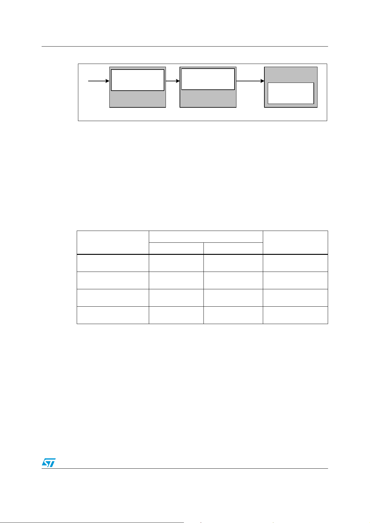
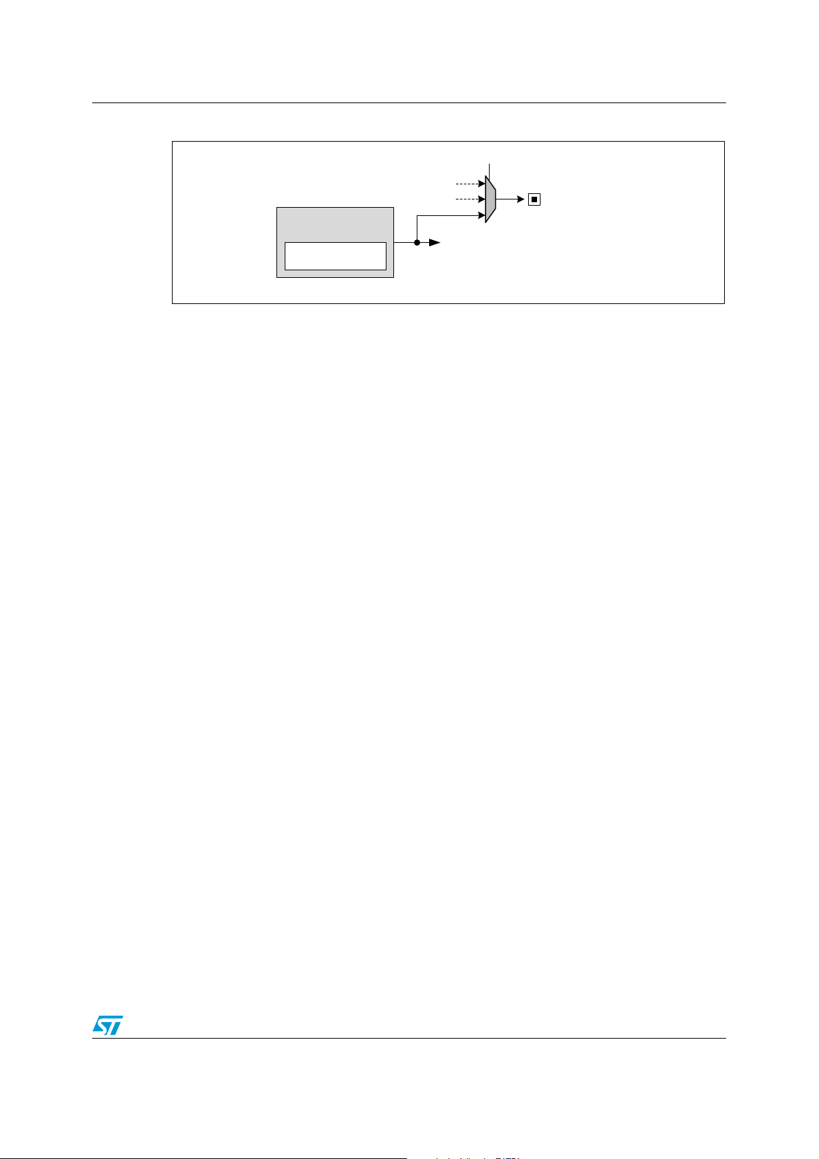
1.7 Time-stamp function
The Time-stamp feature provides the means to automatically save the current calendar.
Figure 14. Time-stamp event procedure
Provided that the time-stamp function is enabled, the calendar is saved in the time-stamp
registers (RTC_TSTR, RTC_TSDR, RTC_TSSSR) when a time-stamp event is detected on
the pin that the TIMESTAMP alternate function is mapped to. When a time-stamp event
occurs, the time-stamp flag bit (TSF) in RTC_ISR register is set.
Note: The time-stamp sub-second register is not available for all products. Please refer to
Table 15: Advanced RTC features.
Table 11. Time-stamp features
What to do How to do it Comments
Setting the TSE bit of
RTC_CR register to 1
Selecting with TSINSEL bit
in RTC_TCR register
Setting the TSIE bit in the
RTC_CR register
By polling on the timestamp flag (TSF
RTC_ISR register
(1)
) in the
Only for F2 series devices.
The TIMESTAMP pin can be either PI8
or PC13.
An interrupt is generated when a timestamp event occurs.
To clear the flag, write zero on the TSF
(2)
bit.
Enable Time-stamp
Map TIMESTAMP pin
alternate function
Detect a time-stamp event by
interrupt
Detect a time-stamp event by
polling
Doc ID 018624 Rev 4 21/44
Page 22

Overview of the STM32 advanced RTC AN3371
Table 11. Time-stamp features (continued)
What to do How to do it Comments
– To clear the flag, write zero on the
TSOVF bit.
– Time-stamp registers (RTC_TSTR
By polling on the timeDetect a Time-stamp
overflow event
1. TSF is set 2 ck_apre cycles after the time-stamp event occurs due to the synchronization
process.
2. To avoid masking a time-stamp event occurring at the same moment, the application must not
write ‘0’ into TSF bit unless it has already read it to‘1’.
3. A time-stamp overflow event is not connected to an interrupt.
4. There is no delay in the setting of TSOVF. This means that if two time-stamp events are close
together, TSOVF can be seen as '1' while TSF is still '0'. As a consequence, it is recommended
to poll TSOVF only after TSF has been set.
(3)
stamp over flow flag
(TSOVF
register.
(4)
) in the RTC_ISR
and RTC_TSDR,
maintain the results of the previous
event.
– If a time-stamp event occurs
immediately after the TSF bit is
supposed to be cleared, then both
TSF and TSOVF bits are set.
RTC_TSSSR
(1)
)
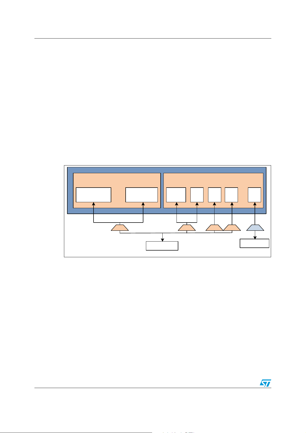
1.8 RTC tamper detection function
The RTC includes n tamper detection inputs. The tamper input active level/edge can be
configured and each one has an individual flag (TAMPxF bit in RTC_ISR register).
A tamper detection event generates an interruption when the TAMPIE bit in RTC_TAFCR
register is set.
The configuration of the tamper filter, “TAMPFLT bits”, defines whether the tamper detection
is activated on edge (set TAMPFLT to “00“), or on level (TAMPFLT must be different from
“00“).
Note: The number of tamper “n” depends on products. Each input has a “TAMPxF” individual flag
in the RTC_TAMP register.
1.8.1 Edge detection on tamper input
When the TAMPFLT bits are set to zero, the tamper input detection triggers when either a
rising edge or a falling edge is observed on the corresponding TAMPLEVEL bit.
22/44 Doc ID 018624 Rev 4
Page 23
AN3371 Overview of the STM32 advanced RTC
MS30113V1
RTC_TAMP1
RTC_TAMPx
STM32
Edge detection
Tamper 1
switch
Tamper x
switch
Figure 15. Tamper with edge detection
Note: With tamper events, sampling and precharge features are deactivated.
Table 12. Tamper features (edge detection)
What to do How to do it Comments
Enable Tamper
Select Tamper1 active edge
detection
Map Tamper1 pin alternate
function
Detect a Tamper1event by
interrupt
Detect a Tamper1 event by
polling
Set the TAMP1E bit of
RTC_TAFCR register to 1
Select with TAMP1TRG bit
in RTC_TAFCR register
Select with TAMP1INSEL
bit in RTC_TAFCR register
Set the TAMPIE bit in the
RTC_TAFCR register
Poll on the time-stamp flag
(TAMP1F) in the RTC_ISR
register
1.8.2 Level detection on tamper input
Setting the tamper filter “TAMPFLT” to a value other than zero means that the tamper input
triggers when a selected level (high or low) is observed on the corresponding TAMPLEVEL
bit.
A tamper detection event is generated when either 2, 4 or 8 (depending on TAMPFLT value)
consecutive samples are observed at the selected level.
The default edge is rising edge.
For F2/4 series devices, the Tamper1
pin can be either PI8 or PC13.
An interrupt is generated when a
tamper detection event occurs.
To clear the flag, write zero on the
TAMP1F bit.
Doc ID 018624 Rev 4 23/44
Page 24

Overview of the STM32 advanced RTC AN3371
MS30114V1
RTC_TAMP1
RTC_TAMPx
STM32
Level detection
Tamper 1
switch
Tamper x
switch
X
X
C1
Cx
MS30115V1
Start sampling
Precharge = 1RTCCLK
Precharge = 2RTCCLK
Precharge =4RTCCLK
RTC clock
Floating input
Switch opened
Figure 16. Tamper with level detection
Using the level detection (tamper filter set to a non-zero value), the tamper input pin can be
precharged by resetting TAMPUDIS through an internal resistance before sampling its state.
In order to support the different capacitance values, the length of the pulse during which the
internal pullup is applied can be 1, 2, 4 or 8 RTCCLK cycles.
Figure 17. Tamper sampling with precharge pulse
Note: When the internal pullup is not applied, the I/Os Schmitt triggers are disabled in order to
avoid extra consumption if the tamper switch is open.
The trade-off between the tamper detection latency (using the precharge feature) and the
power consumption through the weak pullup/pulldown can be reduced by using a tamper
sampling frequency feature.
The tamper sampling frequency is determined by configuring the TAMPFREQ bits in the
RTC_TAMP register.
Note: When using the LSE (32768 Hz) as the RTC clock source, the sampling frequency can be 1,
2, 4, 8, 16, 32, 64, or 128 Hz.
24/44 Doc ID 018624 Rev 4
Page 25

AN3371 Overview of the STM32 advanced RTC
Table 13. Tamper features (level detection)
What to do How to do it Comments
Enable Tamper
Configure Tamper1 filter
count
Configure Tamper1 sampling
frequency
Configure tamper
precharge/discharge
duration
select Tamper1 active
edge/Level detection
Map Tamper1 pin alternate
function
Detect a Tamper1event by
interrupt
Detect a Tamper1 event by
polling
Set the TAMP1E bit of
RTC_TAFCR register to 1
Configure TAMPFLt bits in
RTC_TAFCR register
Configure TAMPFREQ bits
in RTC_TAFCR register
Set/Reset TAMPPUDIS bit
in RTC_TAMPCR register
Select with TAMP1TRG bit
in RTC_TAFCR register
Select with TAMP1INSEL
bit in RTC_TAFCR register
Set the TAMPIE bit in the
RTC_TAFCR register
Poll on the time-stamp
flag (TAMP1F) in the
RTC_ISR register
1.8.3 Active time-stamp on tamper detection event
By setting the TAMPTS bit to 1, any tamper event (with edge or level detection) causes a
time-stamp to occur. Consequently, the time-stamp flag and time-stamp overflow flag are set
at the moment when the tamper flag is set and work in the same manner as when a normal
time-stamp event occurs.
Default value is 0.
Default value is 1Hz
Edge or Level is depending on tamper
filter configuration.
For F2 series devices, the Tamper1 pin
can be either PI8 or PC13.
An interrupt is generated when
tamper detection event occurs.
To clear the flag, write zero on the
TAMP1F bit.
Note: It is not necessary to enable or disable the time-stamp function when using this feature.
1.9 Backup registers
RTC_BKPxR, where x=0 to n backup registers (80 bytes), are reset when a tamper
detection event occurs. These registers are powered-on by VBAT when VDD is switched off,
so that they are not reset by a system reset, and their contents remain valid when the device
operates in low-power mode.
Note: The number “n” of backup registers depends on the product. Please refer to Ta bl e 1 5:
Advanced RTC features.
1.10 RTC and low-power modes
The RTC is designed to minimize the power consumption. The prescalers used for the
calendar are divided into synchronous and asynchronous.
Increasing the value of the asynchronous prescaler reduces the power consumption.
Doc ID 018624 Rev 4 25/44
Page 26

Overview of the STM32 advanced RTC AN3371
The RTC keeps working in reset mode and its registers are only reset by a VDD or VBAT
power-on, if both supplies have previously been powered off or the Backup Domain is reset
on STM32F2xx devices.
Registers are only reset by a power-on reset. RTC register values are not lost after a reset
and the calendar keeps the correct time and date.
After a system reset or a power-on reset, the STM32 operates in Run mode. In addition, the
device supports five low power modes to achieve the best compromise between low power
consumption, short startup time and available wakeup sources.
The RTC peripheral can be active in the following low power modes:
● Sleep mode
● Low power Run mode (only for ULPM and ULPH density devices)
● Low power Sleep mode (only for ULPM and ULPH density devices)
● Standby mode
● Stop mode
Refer to the low power modes section of the STM32 reference manuals for more details
about low power modes.
1.11 Alternate function RTC outputs
The RTC peripheral has two outputs:
● RTC_CALIB, used to generate an external clock.
● RTC_ALARM, a unique output resulting from the multiplexing of the RTC alarm and
wakeup events.
1.11.1 RTC_CALIB output
The RTC_CALIB output is used to generate a variable-frequency signal. Depending on the
user application, this signal can play the role of a reference clock to calibrate an external
device, or be connected to a buzzer to generate a sound.
The signal frequency is configured using the 7 LSB bits (PREDIV_A [6:0]) of the
asynchronous prescaler PREDIV_A[7:0].
RTC_CALIB is the output of bit 4 of the 7-bit asynchronous prescaler PREDIV_A. If
PREDIV_A[5]=0, no signal is output on RTC_CALIB.
Setting 512 Hz as the output signal
1. Select LSE “32768 Hz” as RTC clock source.
2. Set the asynchronous prescaler to the default value “128“.
3. Enable the output calibration by setting “COE” to ‘1’.
4. Select 512 Hz as the calibration output by setting CALSEL to ‘0’.
26/44 Doc ID 018624 Rev 4
Page 27
AN3371 Overview of the STM32 advanced RTC
MS30116V1
512 Hz
AFO_CALIB
1 Hz
CALSEL
Calendar
Synchronous
prescaler
Asynchronous
prescaler
Shadow registers
(RTC_TR and
RTC_DR)
Synchronous 15-bit
prescaler (default=256)
Asynchronous 7-bit
prescaler (default=128)
Ck_Spre
RTC Clock
Setting 1 Hz as the output signal
1. Select LSE “32768 Hz” as the RTC clock source.
2. Set the asynchronous prescaler to the default value “128“.
3. Set the synchronous prescaler to the default value “256“.
4. Enable the output calibration by setting “COE” to ‘1’.
5. Select 1 Hz as the calibration output by setting CALSEL to ‘1’.
Figure 18. RTC_CALIB clock sources
Maximum and minimum RTC_CALIB 512 Hz output frequency
The RTC can output the RTCCLK clock divided by a 7-bit asynchronous prescaler. The
divider factor is configured using bits PREDIV_A[6:0] of the RTC_PRER register.
RTC_CALIB maximum and minimum frequencies are 31.250 kHz and 500 Hz, respectively.
Table 14. RTC_CALIB output frequency versus clock source
RTC_CALIB output frequency
RTC clock source
(PREDIV_A[6:0] = 111 111b)
Minimum
(PREDIV_A[6:0] = 100 000b
(div64)
HSE_RTC = 1MHz 15,625 kHz 31.250 KHz
LSE = 32768 Hz
(2)
LSI
= 32 kHz
(3)
= 37 kHz
LSI
1. PREDIV_A[5] must be set to ‘1’ to enable the RTC_CALIB output signal generation. If PREDIV_A[5] bit is zero, no signal
is output on RTC_CALIB.
2. For STM32L1xx, LSI = 37 KHz.
3. For STM32F2xx and STM32F4xx, LSI = 32 KHz.
(default output frequency)
512 Hz
500 Hz 1 KHz
578.125 Hz 1156.25 Hz
Maximum
(div32)
1.024 KHz
(1)
)
Doc ID 018624 Rev 4 27/44
Page 28

Overview of the STM32 advanced RTC AN3371
MS19535V1
Alarm B
ss, mm, HH/date
Alarm A
ss, mm, HH/date
hh:mm:ss
(12/24 format)
Day/date/
month/year
Calendar
=
=
Alarm A
flag
Alarm B
flag
RTC_ALARM
output
OSEL[1:0]
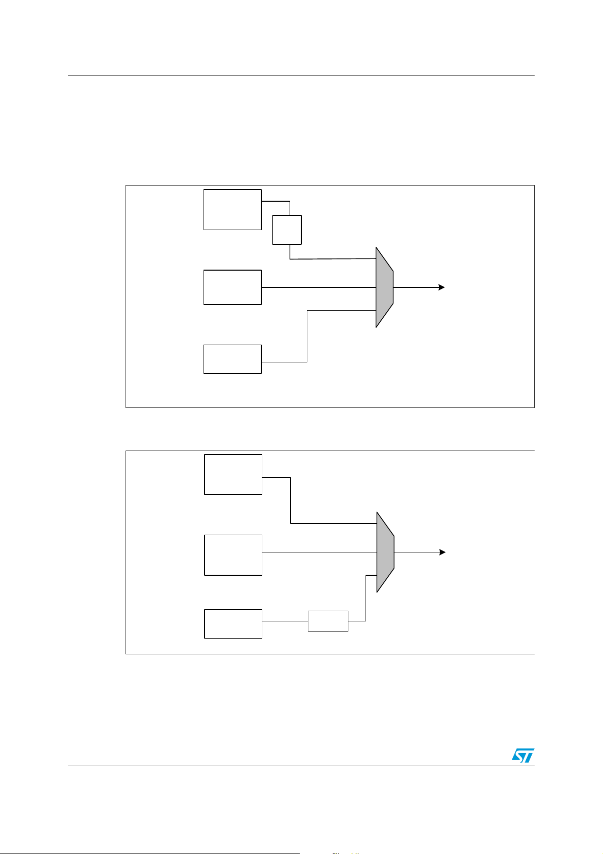
1.11.2 RTC_ALARM output
The RTC_ALARM output can be connected to the RTC alarm unit A or B to trigger an
external action, or routed to the RTC wakeup unit to wake up an external device.
RTC_ALARM output connected to an RTC alarm unit
When the calendar reaches the alarm A pre-programmed value in the RTC_ALRMAR
register (TC_ALRMBR register for alarm B), the alarm flag ALRAF bit (ALRBF bit), in
RTC_ISR register, is set to ‘1’. If the alarm A or alarm B flag is routed to the RTC_ALARM
output (RTC_CR_OSEL[1:0] =”01” for alarm A, and RTC_CR_OSEL[1:0] =”10” for alarm B),
this pin is set to V
when the selected alarm flag is cleared.
Figure 19. Alarm flag routed to RTC_ALARM output
DD or to GND, depending on the polarity selected. The output toggles
RTC_ALARM output connected to the wakeup unit
When the wakeup downcounting timer reaches 0, the wakeup flag is set to ‘1’. If this flag is
selected as the source for the RTC_ALARM output (OSEL[1:0] bits set to ‘11’ in RTC_CR
register), the output will be set depending on the polarity selected and will remain set as
long as the flag is not cleared.
28/44 Doc ID 018624 Rev 4
Page 29
AN3371 Overview of the STM32 advanced RTC
MS19536V1
RTC_ALARM
output
OSEL[1:0]=11
Wakeup unit
16-bit autoreload
timer
Periodic
wakeup flag
Figure 20. Periodic wakeup routed to RTC_ALARM pinout
1.12 RTC security aspects
1.12.1 RTC register write protection
To protect RTC registers against possible parasitic write accesses after reset, the RTC
registers are automatically locked. They must be unlocked to update the current calendar
time and date.
Writing to the RTC registers is enabled by programming a key in the Write protection
register (RTC_WPR).
The following steps are required to unlock the write protection of the RTC register:
1. Write 0xCA into the RTC_WPR register.
2. Write 0x53 into the RTC_WPR register.
Writing an incorrect key automatically reactivates the RTC register write access protection.
1.12.2 Enter/exit initialization mode
The RTC can operate in two modes:
● Initialization mode, where the counters are stopped.
● Free-running mode, where the counters are running.
The calendar cannot be updated while the counters are running. The RTC must
consequently be switched to the Initialization mode before updating the time and date.
When operating in this mode, the counters are stopped. They start counting from the new
value when the RTC enters the Free-running mode.
The INIT bit of the RTC_ISR register enables you to switch from one mode to another, and
the INITF bit can be used to check the RTC current mode.
The RTC must be in Initialization mode to program the time and date registers (RTC_TR
and RTC_DR) and the prescalers register (RTC_PRER). This is done by setting the INIT bit
and waiting until the RTC_ISR_INITF flag is set.
To return to the Free-running mode and restart counting, the RTC must exit the Initialization
mode. This is done by resetting the INIT bit.
Only a power-on reset can reset the calendar. A system reset does not affect it but resets
the shadow registers that are read by the application. They are updated again when the
RSF bit is set. After a system reset, the application can check the INITS status flag in the
RTC_ISR register to verify if the calendar is already initialized. This flag is reset when the
Doc ID 018624 Rev 4 29/44
Page 30

Overview of the STM32 advanced RTC AN3371
calendar year field is set to 0x00 (power-on reset value), meaning that the calendar must be
initialized.
1.12.3 RTC clock synchronization
When the application reads the calendar, it accesses shadow registers that contain a copy
of the real calendar time and date clocked by the RTC clock (RTCCLK). The RSF bit is set in
the RTC_ISR register each time the calendar time and date shadow registers are updated
with the real calendar value. The copy is performed every two RTCCLK cycles,
synchronized with the system clock (SYSCLK). After a system reset or after exiting the
initialization mode, the application must wait for RSF to be set before reading the calendar
shadow registers.
When the system is woken up from low power modes (SYSCLK was off), the application
must first clear the RSF bit, and then wait until it is set again before reading the calendar
registers. This ensures that the value read by the application is the current calendar value,
and not the value before entering the Low power mode.
By setting the “BYPASHAD” bit to ‘1’ in the RTC_CR register, the calendar values are taken
directly from the calendar counters instead of reading the shadow register. In this case, it is
not mandatory to wait for the synchronization time, but the calendar registers consistency
must be checked by the software. The user must read the required calendar field values.
The read operation must then be performed again. The results of the two read sequences
are then compared. If the results match, the read result is correct. If they do not match, the
fields must be read one more time, and the third read result is valid.
Note: After resetting the BYPASHAD bit, the shadow registers may be incorrect until the next
synchronization. In this case, the software should clear the “RSF” bit then wait for the
synchronization (“RSF” should be set) and finally read the shadow registers.
30/44 Doc ID 018624 Rev 4
Page 31

AN3371 Advanced RTC features
2 Advanced RTC features
Table 15. Advanced RTC features
RTC features F0 series F2 series
Asynchronous X (7 bits) X (7 bits) X (7 bits) X (7 bits) X (7 bits)
Prescalers
Synchronous X (15 bits) X (13 bits) X (13 bits) X (15 bits) X (15 bits)
12/24 format X X X X X
Time
Calendar
Hour, minutes
and seconds
Sub-second X
Date X X X X X
Daylight operation X X X X X
Bypass the shadow registers X
Alarms
available
Alarm A X X X X X
Alarm B XXXX
12/24 format X X X X X
Alarm
Time
Hour, minutes
and seconds
Sub-second X
Date or week day X X X X X
ULPM
density
F4 series
ULPH
density
XXXXX
XX
XX
XXXXX
XX
Ta m pe r
detection
Time Stamp
RTC
Outputs
Configurable input mapping X X X
Configurable edge detection X X X X X
Configurable Level detection
(filtering, sampling and
precharge configuration on
X
XX
tamper input)
Number of tamper inputs 2 inputs
2 inputs /
1 event
Configurable input mapping X X
Time
Hours, minutes
and seconds
XXXXX
Sub-seconds X
1 input /
1event
2 inputs /
2 events
3 inputs /
3 events
X
XX
Date X X X X X
Active Time Stamp on tamper
detection event
XXXXX
Alarm event X X X X X
AFO_Alarm
Wakeup event X X X X X
512 Hz X X X X X
AFO_Calib
1 Hz X
XX
Doc ID 018624 Rev 4 31/44
Page 32

Advanced RTC features AN3371
Table 15. Advanced RTC features (continued)
RTC features F0 series F2 series
RTC
Calibration
Synchronizing the RTC X
Reference clock, detection X X X X X
Backup
registers
Coarse Calibration
Smooth Calibration X
Powered-on Vbat X X X
Reset on a tamper detection X X X X X
Reset when Flash readout
protection is disabled
RTC clock source
configuration register
Number of backup registers 5 20 20 20 32
X X X
RCC_BDCR RCC_BDCR RCC_CSR RCC_BDCR RTC_CSR
ULPM
density
XXX
F4 series
XX
XX
ULPH
density
32/44 Doc ID 018624 Rev 4
Page 33

AN3371 RTC firmware driver API
3 RTC firmware driver API
This driver provides a set of firmware functions to manage the following functionalities of the
RTC peripheral:
● Initialization
● Calendar (Time and Date) configuration
● Alarm (alarm A and alarm B) configuration
● Wakeup timer configuration
● Daylight saving configuration
● Output pin configuration
● Digital calibration configuration
● Synchronization configuration
● Time-stamp configuration
● Tamper configuration
● Backup data register configuration
● RTC Tamper and Time-stamp pin selection and Output type configuration
● Interrupts and flag management
For the STM32F2xx family, the RTC driver stm32f2xx_rtc.c/.h can be found in the directory:
STM32F2xx_StdPeriph_Lib_vX.Y.Z\Libraries\STM32F2xx_StdPeriph_Driver.
For the STM32L1xx family, the RTC driver stm32l1xx_rtc.c/.h can be found in the directory:
STM32L1xx_StdPeriph_Lib_vX.Y.Z\Libraries\STM32L1xx_StdPeriph_Driver.
For the STM32F4xx family, the RTC driver stm32f4xx_rtc.c/.h can be found in the directory:
STM32F4xx_StdPeriph_Lib_vX.Y.Z\Libraries\STM32F4xx_StdPeriph_Driver.
For the STM32F0xx family, the RTC driver stm32f0xx_rtc.c/.h can be found in the directory:
STM32F0xx_StdPeriph_Lib_vX.Y.Z\Libraries\STM32F0xx_StdPeriph_Driver.
These four drivers provide a fully compatible API making it easy to move from one product
to another.
3.1 Start with the RTC driver
Before using the RTC features:
● Enable the RTC domain access (see following note)
● Configure the RTC prescaler (Asynchronous and Synchronous) and RTC hour format
using the RTC_Init() function.
Doc ID 018624 Rev 4 33/44
Page 34

RTC firmware driver API AN3371
Note: After a reset, the backup domain (RTC registers, RTC backup data registers and backup
SRAM) is protected against any possible unwanted write access. To enable access to the
RTC domain and RTC registers:
– Enable the Power Controller (PWR) APB1 interface clock using the
RCC_APB1PeriphClockCmd() function.
– Enable the access to the RTC domain using the PWR_BackupAccessCmd()
function on STM32F2xx and STM32F4xx devices, or the PWR_RTCAccessCmd()
function on STM32L1xx and STM32F0xx devices.
– Select the RTC clock source using the RCC_RTCCLKConfig() function.
– Enable RTC Clock using the RCC_RTCCLKCmd() function.
3.1.1 Time and date configuration
To configure the RTC Calendar (Time and Date), use the RTC_SetTime() and
RTC_SetDate() functions.
To read the RTC Calendar, use the RTC_GetTime(), RTC_GetDate() and
RTC_GetSubSecond() functions.
To add or subtract one hour to/from the RTC Calendar, use the
RTC_DayLightSavingConfig() function.
3.1.2 Alarm configuration
RTC Alarm
To configure the RTC alarm, use the RTC_SetAlarm() function.
To enable the selected RTC alarm, use the RTC_AlarmCmd() function.
To read the RTC alarm, use the RTC_GetAlarm() function.
RTC Alarm Sub-second
To configure the RTC alarm sub-second, use the RTC_AlarmSubSecondConfig() function.
To read the RTC alarm sub-second, use the RTC_GetAlarmSubSecond() function.
3.1.3 RTC wakeup configuration
To configure the RTC Wakeup Clock source, use the RTC_WakeUpClockConfig() function.
To configure the RTC WakeUp Counter, use the RTC_SetWakeUpCounter() function.
To enable the RTC WakeUp, use the RTC_WakeUpCmd() function.
To read the RTC WakeUp Counter register, use the RTC_GetWakeUpCounter() function.
34/44 Doc ID 018624 Rev 4
Page 35

AN3371 RTC firmware driver API
3.1.4 Outputs configuration
The RTC has two different outputs:
● AFO_ALARM, used to manage the RTC alarm A, alarm B and WaKeUp signals. To
output the selected RTC signal on RTC_AF1 pin, use the RTC_OutputConfig()
function.
● AFO_CALIB, used to manage the RTC Clock divided by a 64 (512 Hz) signal and the
calendar clock (1 Hz). To output the RTC Clock on the RTC_AF1 pin, use the
RTC_CalibOutputCmd() function.
3.1.5 Digital calibration configuration
To configure the RTC Coarse calibration value and the corresponding sign, use the
RTC_CoarseCalibConfig() function.
To enable the RTC Coarse calibration, use the RTC_CoarseCalibCmd() function.
To configure the RTC smooth calibration value and the calibration period, use the
RTC_SmoothCalibConfig() function.
3.1.6 TimeStamp configuration
To configure the RTC_AF1 trigger and enable the RTC TimeStamp, use the
RTC_TimeStampCmd() function.
To read the RTC TimeStamp Time and Date register, use the RTC_GetTimeStamp()
function.
To read the RTC TimeStamp sub-second register, use the
RTC_GetTimeStampSubSecond() function.
The TAMPER1 alternate function can be mapped either to RTC_AF1(PC13) or RTC_AF2
(PI8) depending on the value of TAMP1INSEL bit in RTC_TAFCR register. You can use the
RTC_TimeStampPinSelection() function to select the corresponding pin.
3.1.7 Tamper configuration
To configure the RTC Tamper trigger, use the RTC_TamperConfig() function.
To configure the RTC Tamper filter, use the RTC_TamperFilterConfig() function.
To configure the RTC Tamper sampling frequency, use the
RTC_TamperSamplingFreqConfig() function.
To configure the RTC Tamper pins input precharge duration, use the
RTC_TamperPinsPrechargeDuration() function.
To enable the precharge of the Tamper pin, use the RTC_TamperPullUpCmd() function.
To enable the TimeStamp on Tamper detection event, use the
RTC_TimeStampOnTamperDetectionCmd() function.
To enable the RTC Tamper, use the RTC_TamperCmd() function.
The TIMESTAMP alternate function can be mapped to either RTC_AF1 or RTC_AF2
depending on the value of the TSINSEL bit in the RTC_TAFCR register. You can use the
RTC_TamperPinSelection() function to select the corresponding pin.
Doc ID 018624 Rev 4 35/44
Page 36

RTC firmware driver API AN3371
3.1.8 Backup data registers configuration
To write to the RTC backup data registers, use the RTC_WriteBackupRegister() function.
To read the RTC backup data registers, use the RTC_ReadBackupRegister() function.
3.2 Function groups and description
The STM32 RTC driver can be divided into 14 function groups related to the functions
embedded in the RTC peripheral.
● RTC configuration to the default reset state
● RTC initialization and configuration functions
● RTC time and date configuration functions
● RTC alarm configuration functions
● RTC wakeup timer configuration functions
● RTC daylight saving configuration functions
● RTC output pin configuration functions
● RTC digital calibration (coarse and smooth) configuration functions
● RTC time-stamp configuration functions
● RTC Tamper configuration functions
● RTC backup registers configuration functions
● RTC tamper, time-stamp pin selection
● RTC shift control synchronization function
● RTC flags and IT management functions
Table 16. RTC function groups
Group
ID
Function name Description
Function used to set the RTC configuration to the default reset state
1
RTC_DeInit
Deinitializes the RTC registers to
their default reset values.
ULPM
density
ULPH
density
F0
series
F2
series
Ye s Ye s Ye s Ye s Ye s
F4
series
36/44 Doc ID 018624 Rev 4
Page 37

AN3371 RTC firmware driver API
Table 16. RTC function groups (continued)
Group
ID
2
Function name Description
Initialization and Configuration
Initializes the RTC registers
according to the specified
RTC_Init
RTC_StructInit
RTC_RefClockCmd
RTC_EnterInitMode Enters the RTC initialization mode. Yes Yes Yes Yes Yes
RTC_ExitInitMode Exits the RTC initialization mode. Yes Yes Yes Yes Yes
RTC_WriteProtectionCmd
RTC_WaitForSynchro
RTC_TimeStructInit
parameters in RTC_InitStruct <Hour
format, Asynchronous predivisor,
Asynchronous predivisor>.
Fills each RTC_InitStruct member
with its default value.
Enables or disables the RTC
reference clock detection.
Enables or disables the RTC
registers write protection.
Waits until the RTC time and date
registers (RTC_TR and RTC_DR)
are synchronized.
Fills each RTC_TimeStruct member
with its default value (Time =
00h:00min:00sec).
ULPM
density
ULPH
density
Ye s Ye s Ye s Ye s Ye s
Ye s Ye s Ye s Ye s Ye s
Ye s Ye s Ye s Ye s Ye s
Ye s Ye s Ye s Ye s Ye s
Ye s Ye s Ye s Ye s Ye s
Ye s Ye s Ye s Ye s Ye s
F0
series
F2
series
F4
series
RTC_BypassShadowCmd
RTC time and date functions
RTC_SetTime
RTC_SetDate
RTC_GetTime Gets the current RTC time. Yes Yes Yes Yes Yes
3
RTC_GetDate Gets the current RTC date. Yes Yes Yes Yes Yes
RTC_DateStructInit
RTC_TimeStructInit
RTC_GetSubSecond
Enables or disables the bypass
shadow feature.
Sets the RTC current time < RTC
hours, RTC minutes, RTC seconds,
RTC 12-hour clock period (AM/PM)>.
Sets the current RTC date. <
Calendar weekday, Calendar Month,
Calendar date, Calendar year>.
Fills each RTC_DateStruct member
with its default value (Monday 01
January xx00).
Fills each RTC_TimeStruct member
with its default value (Time =
00h:00min:00sec).
Gets the RTC current calendar subseconds value.
Ye s Ye s Ye s Ye s Ye s
Ye s Ye s Ye s Ye s Ye s
Ye s Ye s Ye s Ye s Ye s
Ye s Ye s Ye s Ye s Ye s
Ye s Ye s Ye s
Ye s Ye s Ye s
Doc ID 018624 Rev 4 37/44
Page 38
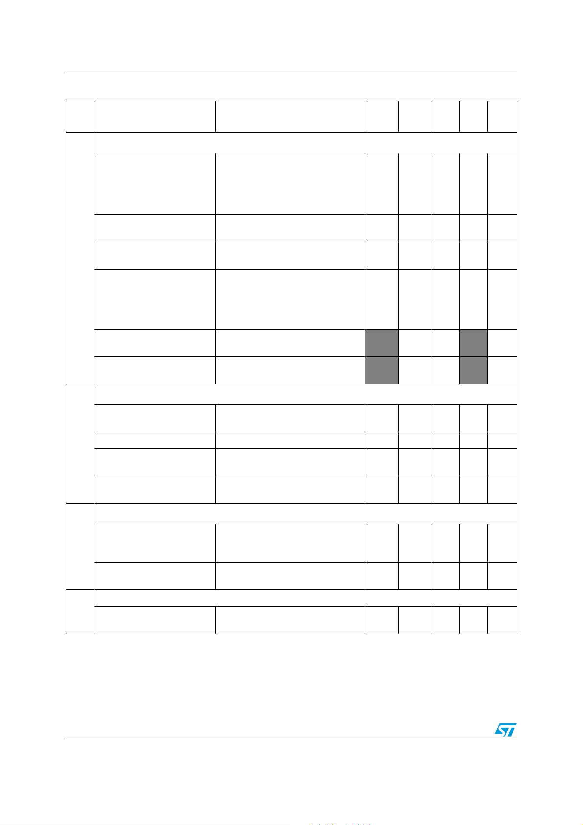
RTC firmware driver API AN3371
Table 16. RTC function groups (continued)
Group
ID
4
Function name Description
RTC alarms functions
RTC_SetAlarm
RTC_GetAlarm
RTC_AlarmCmd
RTC_AlarmStructInit
RTC_AlarmSubSecondConfig
RTC_GetAlarmSubSecond
RTC wakeup timer functions
Sets the RTC specified alarm
configuration:
“Alarm time fields, Alarm masks,
Alarm date/Weekday selection,
Alarm Date/Weekday value”.
Gets the RTC specified alarm
configuration.
Enables or disables the RTC
specified alarm.
Fills each RTC_AlarmStruct member
with its default value (Time =
00h:00mn:00sec / Date = 1st day of
the month/Mask = all fields are
masked).
Configure the RTC alarm A/B subseconds value and mask.
Gets the RTC alarm sub-seconds
value.
ULPM
density
ULPH
density
Ye s Ye s Ye s Ye s Ye s
Ye s Ye s Ye s Ye s Ye s
Ye s Ye s Ye s Ye s Ye s
Ye s Ye s Ye s Ye s Ye s
Ye s Ye s Ye s
Ye s Ye s Ye s
F0
series
F2
series
F4
series
RTC_WakeUpClockConfig
RTC_SetWakeUpCounter Sets the RTC wakeup counter value. Yes Yes Yes Yes Yes
5
RTC_GetWakeUpCounter
RTC_WakeUpCmd
RTC daylight saving functions
RTC_DayLightSavingConfig
6
RTC_GetStoreOperation
RTC output pin configuration function
7
RTC_OutputConfig
Configures the RTC wakeup clock
source.
Returns the RTC wakeup timer
counter value.
Enables or disables the RTC wakeup
timer.
Adds or subtracts one hour to/from
the current time depending on the
daylight saving parameter.
Returns the daylight saving stored
operation.
Configures the RTC output for the
output pinout (RTC_ALARM pin)
Ye s Ye s Ye s Ye s Ye s
Ye s Ye s Ye s Ye s Ye s
Ye s Ye s Ye s Ye s Ye s
Ye s Ye s Ye s Ye s Ye s
Ye s Ye s Ye s Ye s Ye s
Ye s Ye s Ye s Ye s Ye s
38/44 Doc ID 018624 Rev 4
Page 39

AN3371 RTC firmware driver API
Table 16. RTC function groups (continued)
Group
ID
8
9
Function name Description
RTC digital coarse calibration functions
RTC_DigitalCalibConfig
RTC_DigitalCalibCmd
RTC_CalibOutputCmd
RTC_CalibOutputConfig
RTC_SmoothCalibConfig
RTC timestamp functions
RTC_TimeStampCmd
RTC_GetTimeStamp
RTC_GetTimeStampSubSec
ond
Configures the coarse calibration
settings.
Enables or disables the digital
calibration process.
Enables or disables the connection of
the RTCCLK/PREDIV_A[6:0] clock to
be output through the relative pinout
(RTC_CALIB pin).
Configure the calibration pinout
(RTC_CALIB) Selection (1 Hz or 512
Hz).
Configures the smooth calibration
settings.
Enables or disables the RTC Timestamp functionality with the specified
time-stamp pin stimulating edge.
Get the RTC time-stamp value and
masks.
Get the RTC time-stamp subseconds value.
ULPM
density
ULPH
density
Ye s Ye s
Ye s Ye s
Ye s Ye s Ye s Ye s Ye s
Ye s Ye s Ye s
Ye s Ye s Ye s
Ye s Ye s Ye s Ye s Ye s
Ye s Ye s Ye s Ye s Ye s
Ye s Ye s Ye s
F0
series
F2
series
Ye s Ye s
Ye s Ye s
F4
series
RTC tamper functions
RTC_TamperTriggerConfig Configures the tamper edge trigger. Yes Yes Yes Yes Yes
RTC_TamperCmd
RTC_TamperFilterConfig RTC_TamperPullUpCmd.
RTC_TamperSamplingFreqC
10
onfig
RTC_TamperPinsPrechargeD
uration
RTC_TimeStampOnTamperD
etectionCmd
RTC_TamperPullUpCmd
RTC backup registers functions
RTC_WriteBackupRegister
11
RTC_ReadBackupRegister
Enables or disables the tamper
detection.
Configures the tamper sampling
frequency.
Configures the tamper pins input
precharge duration.
Enables or disables the precharge of
tamper pin.
Enables or disables the time-stamp
on Tamper detection event.
Writes data in a specified RTC
backup data register.
Reads data from the specified RTC
backup data register.
Ye s Ye s Ye s Ye s Ye s
Ye s Ye s Ye s
Ye s Ye s Ye s
Ye s Ye s Ye s
Ye s Ye s Ye s
Ye s Ye s Ye s
Ye s Ye s Ye s Ye s Ye s
Ye s Ye s Ye s Ye s Ye s
Doc ID 018624 Rev 4 39/44
Page 40

RTC firmware driver API AN3371
Table 16. RTC function groups (continued)
Group
ID
12
13
14
Function name Description
RTC tamper, timestamp pins selection functions
RTC_OutputTypeConfig
RTC_TimeStampPinSelection Selects the RTC time-stamp pin.
RTC_TamperPinSelection Selects the RTC tamper pin.
RTC Shift control synchronization
RTC_SynchroShiftConfig
RTC flags and interrupts functions
RTC_ITConfig
RTC_GetFlagStatus
RTC_ClearFlag Clears the RTC pending flags. Yes Yes Yes Yes Yes
RTC_GetITStatus
RTC_ClearITPendingBit
Configures the RTC output pin mode
(OpenDrain / PushPull).
Configures the synchronization shift
control settings.
Enables or disables the specified
RTC interrupts.
Checks whether the specified RTC
flag is set or not.
Checks whether the specified RTC
interrupt has occurred or not.
Clears the RTC interrupt pending
bits.
ULPM
density
ULPH
density
Ye s Ye s Ye s Ye s Ye s
Ye s Ye s Ye s
Ye s Ye s Ye s Ye s Ye s
Ye s Ye s Ye s Ye s Ye s
Ye s Ye s Ye s Ye s Ye s
Ye s Ye s Ye s Ye s Ye s
F0
series
F2
series
series
Ye s Ye s
Ye s Ye s
F4
40/44 Doc ID 018624 Rev 4
Page 41

AN3371 Application examples
4 Application examples
The RTC firmware driver is provided with a set of examples, so that you can quickly become
familiar with the RTC peripheral.
This section provides descriptions of examples that are delivered within the STM32F2xx,
STM32F4xx and STM32L1xx Standard Peripherals Libraries available from
http://www.st.com/.
For the STM32F2xx family, the examples can be found in the following directory:
STM32F2xx_StdPeriph_Lib_vX.Y.Z\Project\STM32F2xx_StdPeriph_Examples\RTC\
For the STM32L1xx family, the examples can be found in the following directory:
STM32L1xx_StdPeriph_Lib_vX.Y.Z\Project\STM32L1xx_StdPeriph_Examples\RTC\
For the STM32F4xx family, the examples can be found in the following directory:
STM32F4xx_StdPeriph_Lib_vX.Y.Z\Project\STM32F4xx_StdPeriph_Examples\RTC\
For the STM32F0xx family, the examples can be found in the following directory:
STM32F0xx_StdPeriph_Lib_vX.Y.Z\Project\STM32F0xx_StdPeriph_Examples\RTC\
Table 17. Example descriptions
Example Description Covered features
RTC Hardware
Calendar
RTC Backup
domain
Auto calibration
using LSI
Ta m pe r
detection
(1)
(2)
This example describes how to use the RTC peripheral calendar
features: seconds, minutes, hours (12 or 24 format), day, date, month,
and year.
As an application example, it demonstrates how to set up the RTC
peripheral, in terms of prescaler and interrupts to be used to keep time
and to generate an alarm interrupt.
This example demonstrates and explains how to use the peripherals
available on the Backup domain. These peripherals are the RCC
BDCR register containing the LSE oscillator configuration and the RTC
Clock enable/disable bits.
This example embeds the RTC peripheral and its associated Backup
Data registers, and the Backup SRAM (4KB) with its low power
regulator (which enables it to preserve its contents when the product is
powered by VBAT pin).
As an application example, it demonstrates how to set up the RTC
hardware calendar, and read/write operations for RTC Backup Data
registers and BKPSRAM (Backup SRAM).
This example demonstrates and explains how to use the LSI clock
source auto calibration to get a precise RTC clock.
The Low Speed Internal (LSI) clock is used as the RTC clock source.
The RTC WakeUp is configured to generate an interrupt each 1s. The
WakeUp counter is clocked by the RTC CK_SPRE signal (1Hz) and its
counter is set to zero.
This example shows how to write/read data to/from RTC backup data
registers and demonstrates the Tamper detection feature. It configures
the RTC_AF1 pin Tamper to be falling edge, and enables the Tamper
interrupt. On applying a low level on the RTC_AF1 pin, the RTC backup
data registers are reset and the Tamper interrupt is generated.
– Hardware calendar
– Alarm (interrupt)
– Prescalers
– RTC backup registers
– RTC Backup registers
– Backup SRAM
– Low power regulator
for Backup SRAM
– Hardware calendar
– Wakeup (interrupt)
– Prescalers
– RTC backup registers
– Hardware calendar
– Wakeup (interrupt)
– Tamper (interrupt)
– RTC backup registers
Doc ID 018624 Rev 4 41/44
Page 42

Application examples AN3371
Table 17. Example descriptions (continued)
Example Description Covered features
This example describes how to use the RTC peripheral and the Time
Stamp feature. It configures the RTC_AF1 pin TimeStamp to be falling
Time Stamp
edge and enables the TimeStamp detection. On applying a low level on
the RTC_AF1 pin, the calendar is saved in the time-stamp registers
thanks to the timestamp event detection.
This example illustrates how to use the STM32F4xx new RTC
sub-seconds and Tamper (filter, sampling) features. It simulates
StopWatch
a precise chronometer with 10 record time possibilities stored in
the Backup registers (10 registers for time (second, minutes and
hours) and 10 registers for sub-seconds).
This example provides a short description of how to use the
RTC peripherals with Alarm sub-seconds feature to simulate a
RTC Timer
timer with a refresh time equal to 250 ms ((1 second/ 8) * 2).
The RTC is configured to generate a sub-second interrupt every
125 ms (8 interrupts per second).
1. For Ultra Low Power Medium-density example, Alarm feature is not used.
2. This example is delivered only with F2/4 - series FW examples.
– Time-stamp (interrupt)
– Prescalers
– Wakeup (interrupt)
– Hardware calendar
– RTC backup registers
– Time-stamp
(interrupt)
– Tamper (interrupt)
– Hardware calendar
–RTC backup
registers
– Hardware calendar
– Alarm sub-second
42/44 Doc ID 018624 Rev 4
Page 43

AN3371 Revision history
5 Revision history
Table 18. Document revision history
Date Revision Changes
20-May-2011 1 Initial release
Updated Chapter 1: Overview of the STM32 advanced RTC
Updated Figure 1: RTC calendar fields on page 6
Updated Figure 2: Example of calendar display on an LCD on page 7
Updated Figure 5: Prescalers from RTC clock source to calendar unit
on page 9
Updated Figure 6: Alarm A fields on page 10
Added Section 1.2.2: Alarm sub-second configuration on page 12
Updated Figure 9: Prescalers connected to the wakeup unit for
configurations 2 and 3 on page 16
Updated Table 9: Timebase/wakeup unit period resolution with clock
configuration 2 on page 16
Updated Section 1.4.1: RTC coarse calibration on page 17
24-Nov-2011 2
Added Section 1.4.2: RTC smooth calibration on page 18
Added Section 1.5: Synchronizing the RTC on page 19
Updated Figure 14: Time-stamp event procedure on page 21
Added Section 1.8: RTC tamper detection function on page 22
Added Section 1.11.1: RTC_CALIB output on page 26
Updated Figure 18: RTC_CALIB clock sources on page 27
Added Figure 19: Alarm flag routed to RTC_ALARM output on
page 28
Updated Section 1.12.3: RTC clock synchronization on page 30
Added Section 2: Advanced RTC features on page 31
Added STM32F4xx information to Section 3: RTC firmware driver
API on page 33
Updated Table 17: Example descriptions on page 41
17-Feb-2012 3
24-May-2012 4
Added Ultra Low Power High-density information to the Introduction
Changed all ‘ULPM density devices’ to ‘ULPM and ULPH density
devices’.
Added a ULPH density column to Table 15: Advanced RTC features
and to Table 16: RTC function groups.
Updated the title.
Added F0 series devices and STM32F0xx in the Introduction.
Added a new driver line to Section 3: RTC firmware driver API.
Added ‘and STM32F0xx devices’ to the Note in
with the RTC driver.
Added an F0 series column to Table 15: Advanced RTC features and
to Table 16: RTC function groups.
Doc ID 018624 Rev 4 43/44
Section 3.1: Start
Page 44

AN3371
Please Read Carefully:
Information in this document is provided solely in connection with ST products. STMicroelectronics NV and its subsidiaries (“ST”) reserve the
right to make changes, corrections, modifications or improvements, to this document, and the products and services described herein at any
time, without notice.
All ST products are sold pursuant to ST’s terms and conditions of sale.
Purchasers are solely responsible for the choice, selection and use of the ST products and services described herein, and ST assumes no
liability whatsoever relating to the choice, selection or use of the ST products and services described herein.
No license, express or implied, by estoppel or otherwise, to any intellectual property rights is granted under this document. If any part of this
document refers to any third party products or services it shall not be deemed a license grant by ST for the use of such third party products
or services, or any intellectual property contained therein or considered as a warranty covering the use in any manner whatsoever of such
third party products or services or any intellectual property contained therein.
UNLESS OTHERWISE SET FORTH IN ST’S TERMS AND CONDITIONS OF SALE ST DISCLAIMS ANY EXPRESS OR IMPLIED
WARRANTY WITH RESPECT TO THE USE AND/OR SALE OF ST PRODUCTS INCLUDING WITHOUT LIMITATION IMPLIED
WARRANTIES OF MERCHANTABILITY, FITNESS FOR A PARTICULAR PURPOSE (AND THEIR EQUIVALENTS UNDER THE LAWS
OF ANY JURISDICTION), OR INFRINGEMENT OF ANY PATENT, COPYRIGHT OR OTHER INTELLECTUAL PROPERTY RIGHT.
UNLESS EXPRESSLY APPROVED IN WRITING BY TWO AUTHORIZED ST REPRESENTATIVES, ST PRODUCTS ARE NOT
RECOMMENDED, AUTHORIZED OR WARRANTED FOR USE IN MILITARY, AIR CRAFT, SPACE, LIFE SAVING, OR LIFE SUSTAINING
APPLICATIONS, NOR IN PRODUCTS OR SYSTEMS WHERE FAILURE OR MALFUNCTION MAY RESULT IN PERSONAL INJURY,
DEATH, OR SEVERE PROPERTY OR ENVIRONMENTAL DAMAGE. ST PRODUCTS WHICH ARE NOT SPECIFIED AS "AUTOMOTIVE
GRADE" MAY ONLY BE USED IN AUTOMOTIVE APPLICATIONS AT USER’S OWN RISK.
Resale of ST products with provisions different from the statements and/or technical features set forth in this document shall immediately void
any warranty granted by ST for the ST product or service described herein and shall not create or extend in any manner whatsoever, any
liability of ST.
ST and the ST logo are trademarks or registered trademarks of ST in various countries.
Information in this document supersedes and replaces all information previously supplied.
The ST logo is a registered trademark of STMicroelectronics. All other names are the property of their respective owners.
© 2012 STMicroelectronics - All rights reserved
STMicroelectronics group of companies
Australia - Belgium - Brazil - Canada - China - Czech Republic - Finland - France - Germany - Hong Kong - India - Israel - Italy - Japan -
Malaysia - Malta - Morocco - Philippines - Singapore - Spain - Sweden - Switzerland - United Kingdom - United States of America
www.st.com
44/44 Doc ID 018624 Rev 4
 Loading...