

Page 1

Secure socket layer (SSL) for STM32F217xx microcontroller
1 Introduction
STM32F217xx microcontrollers feature a complete 10/100 Ethernet MAC, supporting MII
and RMII to interface the PHY, with hardware checksums of the IP, UDP, TCP and ICMP
protocols.
One of the advanced features of the STM32F217xx is the hardware cryptographic processor
for AES/128/192/256, Triple DES, DES, SHA-1, MD5 and RNG.
Secure Sockets Layer (SSL) and Transport Layer Security (TLS) cryptographic protocols
provide security for communications over networks, such as the Internet, and allow client
and server applications to communicate in a way that is private and secure.
The purpose of this application note is to present a demonstration package built on top of a
free SSL/TLS library: the PolarSSL library.
This application note is structured as follows:
● A short glossary is provided in Section 2.
● A general introduction to SSL/TLS is presented in Section 3.
● Section 4 introduces the PolarSSL library.
● Section 5 describes the STM32F217xx hardware cryptographic processors.
● Lastly, Section 6 describes the demonstration package for STM32F217xx.
AN3365
Application note
Note: This application targets only STM32F217xx devices, since the cryptographic acceleration is
not embedded in STM32F207xx devices, and it uses the STM3221G-EVAL board as a
hardware platform.
October 2011 Doc ID 018609 Rev 2 1/42
www.st.com
Page 2

Contents AN3365
Contents
1 Introduction . . . . . . . . . . . . . . . . . . . . . . . . . . . . . . . . . . . . . . . . . . . . . . . . 1
2 Glossary . . . . . . . . . . . . . . . . . . . . . . . . . . . . . . . . . . . . . . . . . . . . . . . . . . . 6
3 SSL/TLS protocol overview . . . . . . . . . . . . . . . . . . . . . . . . . . . . . . . . . . . 8
3.1 SSL application layers . . . . . . . . . . . . . . . . . . . . . . . . . . . . . . . . . . . . . . . . 8
3.2 History of the SSL/TLS protocols . . . . . . . . . . . . . . . . . . . . . . . . . . . . . . . . 9
3.3 SSL/TLS sub-protocols . . . . . . . . . . . . . . . . . . . . . . . . . . . . . . . . . . . . . . . 9
3.3.1 SSL Handshake protocol . . . . . . . . . . . . . . . . . . . . . . . . . . . . . . . . . . . . . 9
3.3.2 SSL Record protocol . . . . . . . . . . . . . . . . . . . . . . . . . . . . . . . . . . . . . . . 12
3.3.3 SSL Alert protocol . . . . . . . . . . . . . . . . . . . . . . . . . . . . . . . . . . . . . . . . . 13
3.3.4 Change Cipher Spec protocol . . . . . . . . . . . . . . . . . . . . . . . . . . . . . . . . 13
4 PolarSSL library . . . . . . . . . . . . . . . . . . . . . . . . . . . . . . . . . . . . . . . . . . . 14
4.1 License . . . . . . . . . . . . . . . . . . . . . . . . . . . . . . . . . . . . . . . . . . . . . . . . . . . 14
5 STM32F217xx hardware cryptography . . . . . . . . . . . . . . . . . . . . . . . . . 15
5.1 Cryptographic processor . . . . . . . . . . . . . . . . . . . . . . . . . . . . . . . . . . . . . 15
5.2 Random number generator . . . . . . . . . . . . . . . . . . . . . . . . . . . . . . . . . . . 15
5.3 Hash processor . . . . . . . . . . . . . . . . . . . . . . . . . . . . . . . . . . . . . . . . . . . . 15
6 Description of the demonstration package . . . . . . . . . . . . . . . . . . . . . 16
6.1 Package directories and firmware components . . . . . . . . . . . . . . . . . . . . 16
6.1.1 Package directories . . . . . . . . . . . . . . . . . . . . . . . . . . . . . . . . . . . . . . . . 16
6.1.2 Firmware components . . . . . . . . . . . . . . . . . . . . . . . . . . . . . . . . . . . . . . 17
6.2 Demonstration settings . . . . . . . . . . . . . . . . . . . . . . . . . . . . . . . . . . . . . . . 19
6.2.1 PHY interface configuration . . . . . . . . . . . . . . . . . . . . . . . . . . . . . . . . . . 19
6.2.2 MAC and IP address settings . . . . . . . . . . . . . . . . . . . . . . . . . . . . . . . . 20
6.2.3 STM3221G-EVAL settings . . . . . . . . . . . . . . . . . . . . . . . . . . . . . . . . . . . 20
6.3 How to use the demonstration . . . . . . . . . . . . . . . . . . . . . . . . . . . . . . . . . 21
6.3.1 SSL client demonstration . . . . . . . . . . . . . . . . . . . . . . . . . . . . . . . . . . . . 21
6.3.2 SSL server demonstration . . . . . . . . . . . . . . . . . . . . . . . . . . . . . . . . . . . 24
6.4 Memory footprint of the SSL demonstrations . . . . . . . . . . . . . . . . . . . . . . 28
6.4.1 SSL client demonstration . . . . . . . . . . . . . . . . . . . . . . . . . . . . . . . . . . . . 28
2/42 Doc ID 018609 Rev 2
Page 3

AN3365 Contents
6.4.2 SSL server demonstration . . . . . . . . . . . . . . . . . . . . . . . . . . . . . . . . . . . 29
7 Conclusion . . . . . . . . . . . . . . . . . . . . . . . . . . . . . . . . . . . . . . . . . . . . . . . . 30
8 References . . . . . . . . . . . . . . . . . . . . . . . . . . . . . . . . . . . . . . . . . . . . . . . . 31
Appendix A Additional information. . . . . . . . . . . . . . . . . . . . . . . . . . . . . . . . . . . . 32
A.1 Flowcharts. . . . . . . . . . . . . . . . . . . . . . . . . . . . . . . . . . . . . . . . . . . . . . . . . 32
A.2 Project configuration . . . . . . . . . . . . . . . . . . . . . . . . . . . . . . . . . . . . . . . . . 34
A.2.1 LwIP configuration . . . . . . . . . . . . . . . . . . . . . . . . . . . . . . . . . . . . . . . . . 34
A.2.2 PolarSSL configuration . . . . . . . . . . . . . . . . . . . . . . . . . . . . . . . . . . . . . . 35
A.2.3 FreeRTOS configuration . . . . . . . . . . . . . . . . . . . . . . . . . . . . . . . . . . . . . 36
A.3 Running SSL server demo with Mozilla 3.6.3 . . . . . . . . . . . . . . . . . . . . . . 37
A.4 Running SSL server demo with IE8 . . . . . . . . . . . . . . . . . . . . . . . . . . . . . 39
9 Revision history . . . . . . . . . . . . . . . . . . . . . . . . . . . . . . . . . . . . . . . . . . . 41
Doc ID 018609 Rev 2 3/42
Page 4

List of tables AN3365
List of tables
Table 1. STM3221G-EVAL jumpers configuration . . . . . . . . . . . . . . . . . . . . . . . . . . . . . . . . . . . . . . 20
Table 2. SSL client demonstration footprint . . . . . . . . . . . . . . . . . . . . . . . . . . . . . . . . . . . . . . . . . . . 28
Table 3. SSL server demonstration footprint . . . . . . . . . . . . . . . . . . . . . . . . . . . . . . . . . . . . . . . . . . 29
Table 4. lwIP options for SSL server demonstration . . . . . . . . . . . . . . . . . . . . . . . . . . . . . . . . . . . . . 34
Table 5. lwIP options for SSL client demonstration . . . . . . . . . . . . . . . . . . . . . . . . . . . . . . . . . . . . . 34
Table 6. PolarSSL options: config.h file for SSL server demonstration . . . . . . . . . . . . . . . . . . . . . . 35
Table 7. PolarSSL options: config.h file for SSL client demonstration . . . . . . . . . . . . . . . . . . . . . . . 36
Table 8. FreeRTOS configuration for SSL client demonstration. . . . . . . . . . . . . . . . . . . . . . . . . . . . 36
Table 9. FreeRTOS configuration for SSL server demonstration . . . . . . . . . . . . . . . . . . . . . . . . . . . 36
Table 10. Document revision history . . . . . . . . . . . . . . . . . . . . . . . . . . . . . . . . . . . . . . . . . . . . . . . . . 41
4/42 Doc ID 018609 Rev 2
Page 5

AN3365 List of figures
List of figures
Figure 1. SSL application architecture . . . . . . . . . . . . . . . . . . . . . . . . . . . . . . . . . . . . . . . . . . . . . . . . . 8
Figure 2. SSL sub-protocols . . . . . . . . . . . . . . . . . . . . . . . . . . . . . . . . . . . . . . . . . . . . . . . . . . . . . . . . 9
Figure 3. SSL Handshake protocol . . . . . . . . . . . . . . . . . . . . . . . . . . . . . . . . . . . . . . . . . . . . . . . . . . 10
Figure 4. Handshake protocol to resume an SSL session . . . . . . . . . . . . . . . . . . . . . . . . . . . . . . . . . 12
Figure 5. SSL Record protocol. . . . . . . . . . . . . . . . . . . . . . . . . . . . . . . . . . . . . . . . . . . . . . . . . . . . . . 12
Figure 6. Demonstration package structure. . . . . . . . . . . . . . . . . . . . . . . . . . . . . . . . . . . . . . . . . . . . 17
Figure 7. PolarSSL & LwIP connection . . . . . . . . . . . . . . . . . . . . . . . . . . . . . . . . . . . . . . . . . . . . . . . 19
Figure 8. SSL client demonstration architecture . . . . . . . . . . . . . . . . . . . . . . . . . . . . . . . . . . . . . . . . 21
Figure 9. SSL client demonstration . . . . . . . . . . . . . . . . . . . . . . . . . . . . . . . . . . . . . . . . . . . . . . . . . . 22
Figure 10. ssl_server application window . . . . . . . . . . . . . . . . . . . . . . . . . . . . . . . . . . . . . . . . . . . . . . 23
Figure 11. HyperTerminal window . . . . . . . . . . . . . . . . . . . . . . . . . . . . . . . . . . . . . . . . . . . . . . . . . . . . 24
Figure 12. SSL server demonstration architecture . . . . . . . . . . . . . . . . . . . . . . . . . . . . . . . . . . . . . . . 25
Figure 13. SSL server demonstration . . . . . . . . . . . . . . . . . . . . . . . . . . . . . . . . . . . . . . . . . . . . . . . . . 26
Figure 14. HTML page displayed on successful connection . . . . . . . . . . . . . . . . . . . . . . . . . . . . . . . . 26
Figure 15. HyperTerminal SSL server connection status . . . . . . . . . . . . . . . . . . . . . . . . . . . . . . . . . . 27
Figure 16. SSL client task flowchart. . . . . . . . . . . . . . . . . . . . . . . . . . . . . . . . . . . . . . . . . . . . . . . . . . . 32
Figure 17. SSL server task flowchart . . . . . . . . . . . . . . . . . . . . . . . . . . . . . . . . . . . . . . . . . . . . . . . . . . 33
Figure 18. Untrusted connection dialog 1 . . . . . . . . . . . . . . . . . . . . . . . . . . . . . . . . . . . . . . . . . . . . . . 37
Figure 19. Untrusted connection dialog 2 . . . . . . . . . . . . . . . . . . . . . . . . . . . . . . . . . . . . . . . . . . . . . . 37
Figure 20. Add Security Exception dialog . . . . . . . . . . . . . . . . . . . . . . . . . . . . . . . . . . . . . . . . . . . . . . 38
Figure 21. Task status page . . . . . . . . . . . . . . . . . . . . . . . . . . . . . . . . . . . . . . . . . . . . . . . . . . . . . . . . 38
Figure 22. Cannot display webpage error message . . . . . . . . . . . . . . . . . . . . . . . . . . . . . . . . . . . . . . 39
Figure 23. Certificate error message . . . . . . . . . . . . . . . . . . . . . . . . . . . . . . . . . . . . . . . . . . . . . . . . . . 40
Figure 24. Task status page . . . . . . . . . . . . . . . . . . . . . . . . . . . . . . . . . . . . . . . . . . . . . . . . . . . . . . . . 40
Doc ID 018609 Rev 2 5/42
Page 6

Glossary AN3365
2 Glossary
A
AES: Advanced Encryption Standard
ANSI: American National Standards Institute
API: Application Programming Interface
ARC4: Alleged Rivest Cipher 4
ARP: Address Resolution Protocol
C
CA: Certification Authority
CBC: Cipher Block Chaining
CTR: Counter
D
DES: Data Encryption Standard
DHCP: Dynamic Host Configuration Protocol
DHM: Diffie-Hellman
E
ECB: Electronic CodeBook
F
FIPS: Federal Information Processing Standard
H
HAVEGE: Hardware Volatile Entropy Gathering and Expansion
HMAC: Hash Message Authentication Code
HTTP: Hypertext Transfer Protocol
HTTPS: Hypertext Transfer Protocol Secure
I
IETF: Internet Engineering Task Force
ICMP: Internet Control Message Protocol
IGMP: Internet Group Management Protocol
L
LwIP: Lightweight IP
6/42 Doc ID 018609 Rev 2
Page 7

AN3365 Glossary
M
MAC: Message Authentication Code
MAC address: Media Access Control address
MCO: Microcontroller Clock Output
MD2: Message Digest Algorithm 2
MII: Media Independent Interface
P
PPP: Point-to-Point Protocol
R
RMII: Reduced Media Independent Interface
RNG: Random Number Generator
RSA: Rivest, Shamir, & Adleman
S
SHA-1: Secure Hashing Algorithm 1
SNMP: Simple Network Management Protocol
SSL: Secure Sockets Layer,
T
TCP/IP: Transmission Control Protocol/Internet Protocol
TLS: Transport Layer Security
T-DES/3-DES: Triple DES
U
UDP: User Datagram Protocol
URL: Uniform Resource Locator
USART: Universal Synchronous & Asynchronous Receiver Transmitter
Doc ID 018609 Rev 2 7/42
Page 8
SSL/TLS protocol overview AN3365
Application layer
SSL/TSL layer
TCP layer
IP layer
Physical layer
MS18970V1
3 SSL/TLS protocol overview
The Secure Socket Layer (SSL) and Transport Layer Security (TLS) protocols provide
communications security over the Internet and allow client/server applications to
communicate in a way that is private and reliable. These protocols are layered above a
transport protocol such as TCP/IP.
SSL is the standard security technology for creating an encrypted link between server and
client. This link ensures that all communication data remains private and secure.
The major objectives of SSL/TLS are:
● Provide data integrity between two communicating applications.
● Protect information transmitted between server and client.
● Authenticate the server to the client.
● Allow the client and server to select the cryptographic algorithms that they both
support.
● Optionally authenticate the client to the server.
● Use public-key encryption techniques to generate shared secrets.
● Establish an encrypted SSL connection.
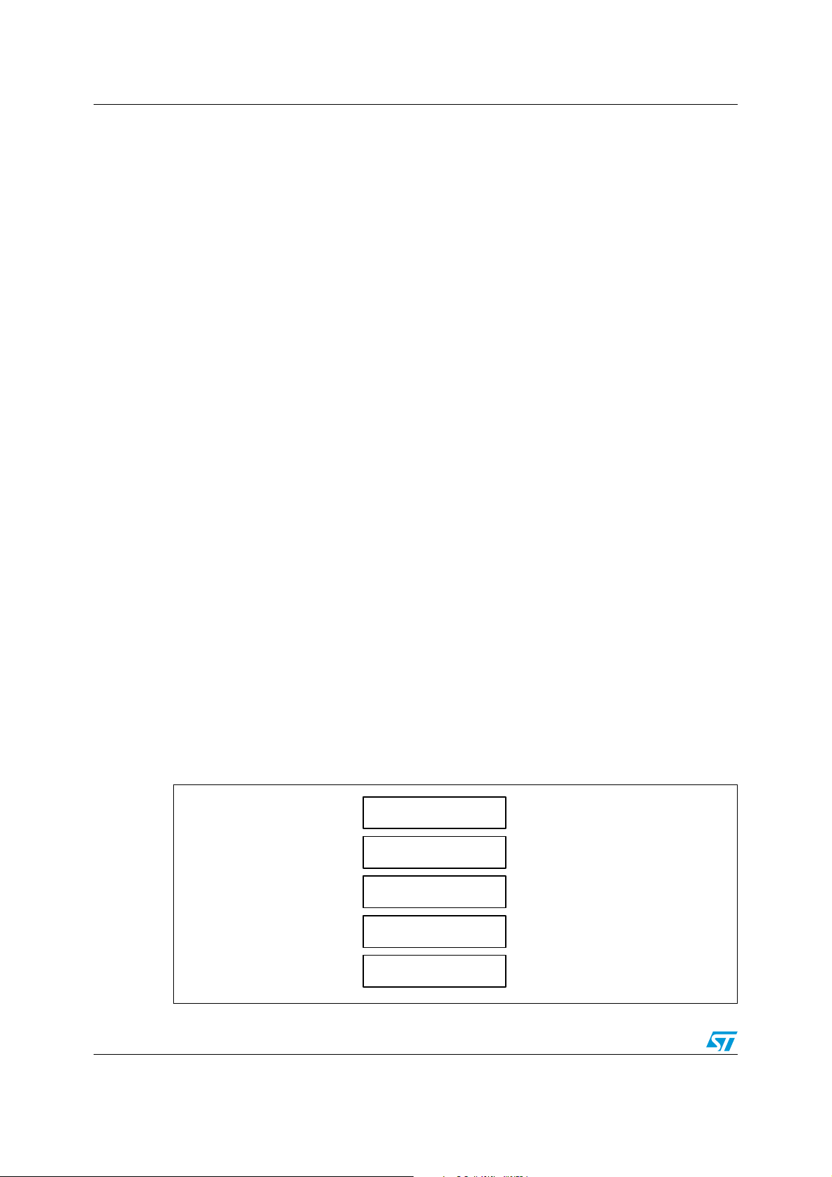
3.1 SSL application layers
The SSL/TLS application consists of five layers:
● Application layer: the Application Layer refers to the higher-level protocols used by
most applications for network communication.
● SSL/TLS layer: the SSL/TLS layer provides security communication over the Internet.
● TCP layer: the Transport Layer's responsibilities include end-to-end message transfer
capabilities independent of the underlying network, along with error control,
segmentation, flow control, congestion control, and application addressing.
● IP layer: the Internet Protocol layer is responsible for addressing hosts and routing
packets from a source host to the destination host.
● Physical layer: the Physical Layer consists of the basic hardware transmission
technologies of a network.
Figure 1. SSL application architecture
8/42 Doc ID 018609 Rev 2
Page 9
AN3365 SSL/TLS protocol overview
3.2 History of the SSL/TLS protocols
SSL was developed by Netscape in 1994 to secure transactions over the Internet. Soon
after, the Internet Engineering Task Force (IETF) began work to develop a standard protocol
to provide the same functionality.
● SSL 1.0 (Netscape, 1993): Internal Netscape design.
● SSL 2.0 (Netscape, 1994): This version contained a number of security flaws.
● SSL 3.0 (Netscape, 1996): All Internet browsers support this version of the protocol.
● TLS 1.0 (IETF, 1999): This version was defined in RFC 2246 as an upgrade to SSL 3.0.
“The differences between this protocol and SSL 3.0 are not dramatic, but they are
significant enough that TLS 1.0 and SSL 3.0 do not interoperate”: [1]: RFC 2246: The
TLS protocol version 1.0
Note: The “SSL/TLS” protocols is referred to as “SSL” throughout this document.
3.3 SSL/TLS sub-protocols
The SSL protocol includes four sub-protocols: the SSL Record protocol, the SSL
Handshake protocol, the SSL Alert protocol and the SSL Change Cipher Spec protocol.
Figure 2. SSL sub-protocols
3.3.1 SSL Handshake protocol
The SSL session state is controlled by the SSL Handshake protocol. This protocol involves
using the SSL record protocol to exchange a series of messages between SSL server and
SSL client when they first start communicating. This exchange of messages is designed to
facilitate the following actions:
● The protocol version SSL 3.0 or TLS 1.0
● Allow the client and server to select the cryptographic algorithms, or ciphers, that they
both support
● Authenticate the server to the client
● Optionally authenticate the client to the server
● Use public-key encryption techniques to generate shared secrets
● Establish an encrypted SSL connection
Doc ID 018609 Rev 2 9/42
Page 10
SSL/TLS protocol overview AN3365
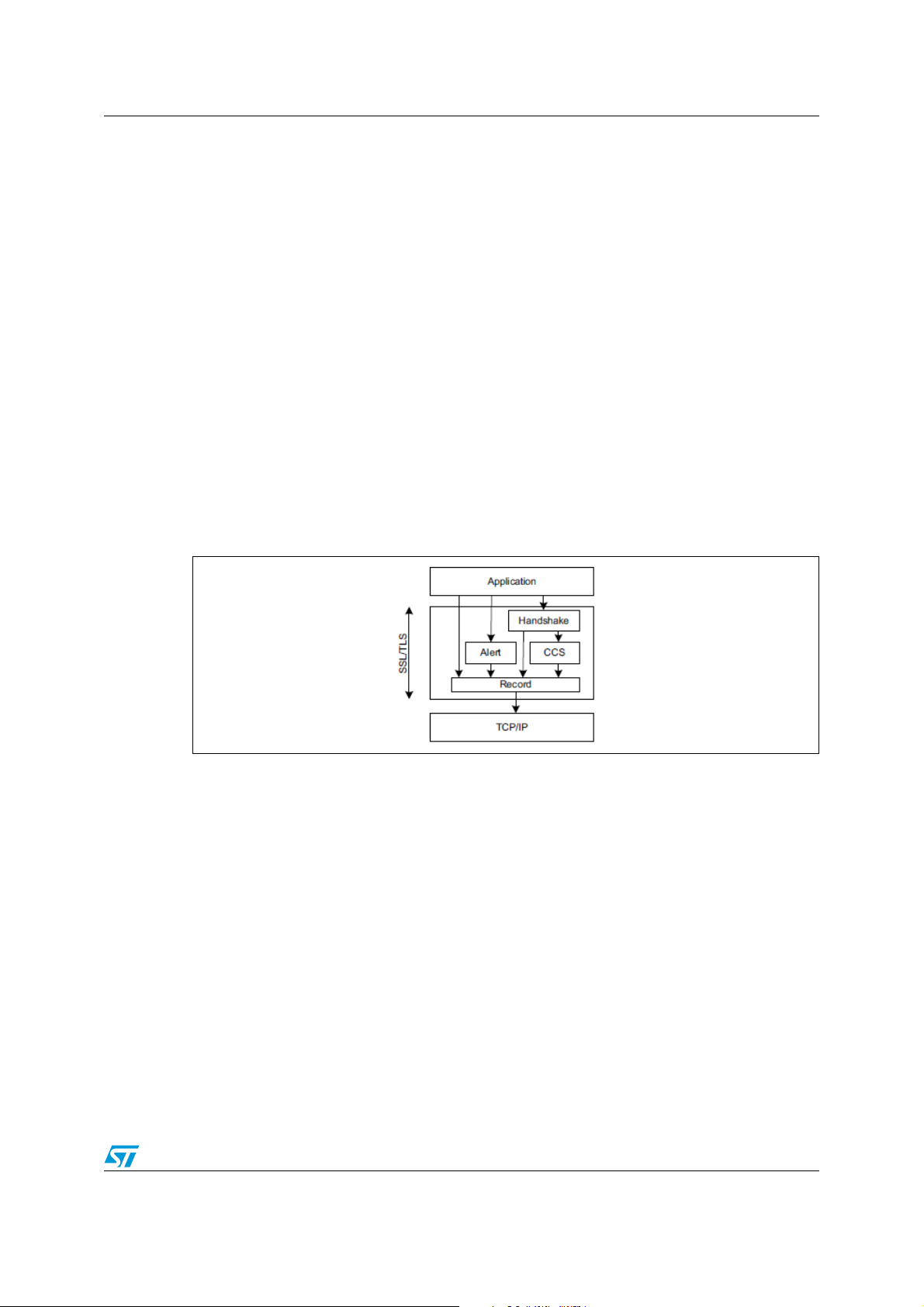
Figure 3. SSL Handshake protocol
1. The client sends a ClientHello message specifying the highest SSL protocol version
(SSL 3.0 or TLS 1.0) it supports, a random number, a list of cipher suites and
compression methods.
2. Server responds with a ServerHello message that contains the chosen protocol
version, another random number, cipher suite and compression method from the
choices offered by the client, and the session ID.
10/42 Doc ID 018609 Rev 2
Page 11

AN3365 SSL/TLS protocol overview
Note: The client and the server must support at least one common cipher suite, or else the
Handshake protocol fails. The server generally chooses the strongest common cipher suite
they both support.
3. The server sends its digital certificate in an optional certificate message, for example,
the server uses X.509 digital certificates.
4. If no certificate is sent, an optional ServerKeyExchange message is sent containing the
server public information.
5. If the server requires a digital certificate for client authentication, an optional
CertificateRequest message is appended.
6. The server sends a ServerHelloDone message indicating the end of this phase of
negotiation.
7. If the server has sent a CertificateRequest message, the client must send its X.509
client certificate in a Certificate message.
8. The client sends a ClientKeyExchange message. This message contains the premaster secret number used in the generation of the symmetric encryption keys and the
message authentication code (MAC) keys. The client encrypts pre-master secret
number with the public key of the server.
Note: The public key is sent by the server in the digital certificate or in ServerKeyExchange
message.
9. If the client sent a digital certificate to the server, the client sends a CertificateVerify
message signed with the client's private key. By verifying the signature of this message,
the server can explicitly verify the ownership of the client digital certificate.
10. The client sends a ChangeCipherSpec message announcing that the new parameters
(cipher method, keys) have been loaded.
11. The client sends a Finished message; it is the first message encrypted with the new
cipher method and keys.
12. The server responds with a ChangeCipherSpec and a Finished message from its end.
13. The SSL Handshake protocol ends and the encrypted exchange of application data
can be started.
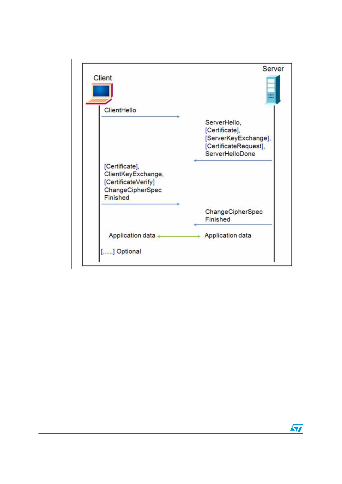
Resuming SSL session
When the client and the server decide to resume a previous session or to duplicate an
existing session (instead of negotiating new security parameters), the message flow is as
follows:
1. The client sends a ClientHello message using the Session ID of the session to be
resumed.
2. The server checks its session cache for a match. If a match is found, and the server is
willing to re-establish the connection under the specified session state, it sends a
ServerHello message with the same Session ID value.
3. Both client and server must send ChangeCipherSpec messages and proceed directly
to the Finished messages.
4. Once the re-establishment is complete, the client and server may begin to exchange
encrypted application data.
Note: If a Session ID match is not found, the server generates a new session ID and the client and
server perform a full Handshake protocol [1]: RFC 2246: The TLS protocol version 1.0.
Doc ID 018609 Rev 2 11/42
Page 12
SSL/TLS protocol overview AN3365
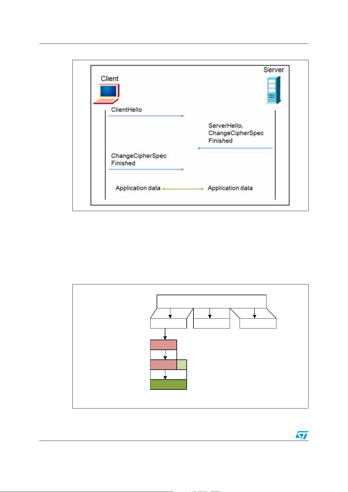
Application data
-F1- -F2- -Fn-
Compression
Fragment
Authentification
Encryption
MS18971V1
Figure 4. Handshake protocol to resume an SSL session
3.3.2 SSL Record protocol
The Record protocol takes messages to be transmitted, fragments the data into
manageable blocks, optionally compresses the data, applies a MAC, encrypts, and
transmits the results.
The received data is decrypted, verified, decompressed, and reassembled, then delivered to
higher level clients.
Figure 5. SSL Record protocol
12/42 Doc ID 018609 Rev 2
Page 13

AN3365 SSL/TLS protocol overview
3.3.3 SSL Alert protocol
The SSL Alert protocol signals problems with the SSL session ranging from simple warnings
(unknown certificate, revoked certificate, expired certificate) to fatal error messages that
immediately terminate the SSL connection.
3.3.4 Change Cipher Spec protocol
The SSL Change Cipher Spec protocol consists of a single message that indicates the end
of the SSL Handshake protocol.
Note: For more information about SSL protocols, please refer to [1]: RFC 2246: The TLS protocol
version 1.0.
Doc ID 018609 Rev 2 13/42
Page 14

PolarSSL library AN3365
4 PolarSSL library
PolarSSL is a light-weight open source cryptographic and SSL/TLS library written in C. This
library contains all needed functions to implement an SSL/TLS server or client. It contains
also a set of hashing functions and cryptographic algorithms.
Features:
● SSL 3.0 and TLS 1.0 client/server support
● X.509 digital certificate
● Symmetric encryption algorithms: AES, Triple DES, DES, ARC4, Camellia,…
● Hash functions: MD2, MD4, MD5, SHA-1, SHA-256, SHA-384, SHA-512
● Message authentication code: HMAC MD2, HMAC MD4, HMAC MD5, HMAC SHA-1
● Software random number generator: HAVEGE
● Public key cryptography: RSA and Diffie-Hellman (DHM) key exchange
The source code of the PolarSSL library can be downloaded from this link:
http://polarssl.org/download_overview
4.1 License
PolarSSL is licensed according to the dual licensing model. PolarSSL is available under the
open source GPL version 2 license, as well as under a commercial license for closed source
projects.
For detailed information about licensing, please refer to the PolarSSL licensing webpage
http://polarssl.org/licensing
14/42 Doc ID 018609 Rev 2
Page 15

AN3365 STM32F217xx hardware cryptography
5 STM32F217xx hardware cryptography
As described in Section 4, the PolarSSL library contains a set of symmetric encryption
algorithms (AES 128/192/256, Triple DES), hashing functions (MD5, SHA-1) and a software
random number generator (HAVEGE). All these functions and algorithms are needed to
implement an SSL/TLS application.
To off-load the CPU from encryption/decryption, hash and RNG (random number generator)
tasks, all these functions and algorithms are implemented using the hardware acceleration
AES 128/192/256, Triple DES, MD5, SHA-1 and analog RNG embedded in STM32F217xx.
5.1 Cryptographic processor
The cryptographic processor can be used to both encipher and decipher data using the
Triple-DES or AES algorithm. It is a fully compliant implementation of the following
standards:
● The data encryption standard (DES) and Triple-DES (TDES) as defined by the Federal
Information Processing Standards Publication “FIPS PUB 46-3, 1999 October 25”. It
follows the American National Standards Institute (ANSI) X9.52 standard.
● The advanced encryption standard (AES) as defined by Federal Information
Processing Standards Publication “FIPS PUB 197, 2001 November 26”
The CRYP processor may be used for both encryption and decryption in the Electronic
codebook (ECB) mode, the Cipher block chaining (CBC) mode or the Counter (CTR) mode
(in AES only).
5.2 Random number generator
The RNG processor is a random number generator, based on a continuous analog noise,
that provides a random 32-bit value to the host when read.
5.3 Hash processor
The hash processor is a fully compliant implementation of the secure hash algorithm (SHA-
1), the MD5 (message-digest algorithm 5) hash algorithm and the HMAC (keyed-hash
message authentication code) algorithm suitable for a variety of applications. It computes a
message digest (160 bits for the SHA-1 algorithm, 128 bits for the MD5 algorithm) for
messages of up to (2
messages by means of hash functions. HMAC algorithms consist in calling the SHA-1 or
MD5 hash function twice.
Note: For more detailed information, please refer to the CRYP, HASH and RNG sections of [2]:
RM0033: STM32F205xx, STM32F207xx, STM32F215xx and STM32F217xx microcontroller
family reference manual.
64
- 1) bits, while HMAC algorithms provide a way of authenticating
Doc ID 018609 Rev 2 15/42
Page 16

Description of the demonstration package AN3365
6 Description of the demonstration package
The demonstration package contains two demonstrations running on top of the PolarSSL
library and LwIP stack:
● SSL Client demonstration: This demonstration proves the ability of the STM32F217xx
device to exchange messages with a server over TCP/IP connectivity through a SSL
connection. This demonstration allows you to connect the STM3221G-EVAL board to a
secure web server with SSL protocol.
● SSL server demonstration: SSL server is a combination of HTTP with SSL protocol to
provide encryption and secure identification of the server. This demonstration allows
you to connect from a web browser to a STM3221G-EVAL board using SSL protocol.
6.1 Package directories and firmware components
6.1.1 Package directories
The demonstration package consists of five main folders listed below:
● Libraries: This folder contains all the subdirectories and files that make up the core of
the STM32F2xx Standard Peripheral library.
● Project: This folder contains the demo header and source files.
● FreeRTOS: This folder contains the real-time kernel source code and all directories
associated with the scheduler source code.
– include: contains the scheduler header files.
– portable: contains the STM32 specific code, scheduler port layer for compiler and
memory management files.
● LwIP: This folder contains all the header and source files for the TCP/IP stack.
● PolarSSL: This folder contains all the header and source files for the PolarSSL 0.12.1
library.
16/42 Doc ID 018609 Rev 2
Page 17

AN3365 Description of the demonstration package
Figure 6. Demonstration package structure
6.1.2 Firmware components
Both demonstrations are based on three software modules: LwIP-1.3.2 (a free TCP/IP
stack), PolarSSL-0.12.1 (a free SSL/TLS library) and FreeRTOS-6.1.0 (a free real-time
kernel). These modules are described below.
LwIP stack
LwIP is a free TCP/IP stack developed by Adam Dunkels at the Swedish Institute of
Computer Science (SICS) and licensed under the BSD license. The source code can be
downloaded from this link: http://download.savannah.gnu.org/releases/lwip/
The lwIP TCP/IP stack supports the following protocols: IPv4, IPv6, UDP, TCP, ICMP, IGMP,
SNMP, ARP and PPP. It does not include protocols from the application layer, like HTTP or
HTTPS.
The lwIP offers three types of API (application programming interface):
● Raw API: native API designed to be used without an operating system. This API is
used by the core stack for interaction between the various protocols.
● Netconn API: sequential API with a higher level of abstraction than the raw API. To use
the Netconn API, an operating system is needed. All packet processing (input and
output) is done inside a dedicated thread (the tcpip thread). The application threads
communicate with this core thread using message boxes and semaphores.
● Socket API: based on the Berkeley socket interface (BSD Socket). To use the Socket
API, an operating system is needed.
Doc ID 018609 Rev 2 17/42
Page 18

Description of the demonstration package AN3365
PolarSSL library
PolarSSL is a free library used to implement a secure application based on SSL/TLS
protocols.
The official release of this library does not provide any port to any microcontroller: you need
to do it by yourself. The PolarSSL library comes with a file called net.c that works as an
interface between the library and the LwIP stack. To use PolarSSL, you need to modify this
file to support the specified stack.
net.c contains functions that ensure the transfer of the frames between PolarSSL and the
lwIP stack. Its main functions are:
● net_recv which should be called when a packet is ready to be read from the stack.
● net_send which should be called when a packet is ready to be send to the stack.
The connection layer of PolarSSL uses the socket API to communicate with the TCP/IP
stack.
Note: The API used to build the demonstration is the socket API, which is shared between
PolaSSL and the LwIP stack.
FreeRTOS
FreeRTOS is an open-source mini real-time Kernel for embedded devices. The source code
can be downloaded from this link: http://www.freertos.org/
Features:
● Scheduler operation:
– Pre-emptive: always runs the highest priority available task.
– Cooperative: context switches only occur if a task blocks, or explicitly calls
taskYIELD() (macro used to force a context switch).
● Inter-Process Communication: the communication between tasks is achieved via the
message queue and the binary semaphores.
● The number of available priorities can be changed as needed.
18/42 Doc ID 018609 Rev 2
Page 19

AN3365 Description of the demonstration package
Figure 7. PolarSSL & LwIP connection
6.2 Demonstration settings
6.2.1 PHY interface configuration
The demonstration firmware is used to interface the PHY with the two modes: MII and RMII.
To select the PHY interface mode you wish to use, go to the main.h file and choose one of
the two defines:
#define MII_MODE
#define RMII_MODE
For the MII mode, the PHY clock can be taken from the external crystal or from the STM32
via the MCO pin if both MII_MODE and PHY_CLOCK_MCO are defined in the main.h file.
Note: In RMII mode, it is not possible to use MCO to output the 50 MHz clock to PHY due to the
PLL limitation explained in chapter 2.6.5 of STM32F20x & STM32F21x Errata sheet
(ES0005). In such a case, it is possible to provide the 50 MHz clock by soldering a 50 MHz
oscillator (ref SM7745HEV-50.0M or equivalent) on the U3 footprint located under CN3 and
also by removing the jumper on JP5. This oscillator is not provided with the board. For more
details, please refer to STM3220G-EVAL evaluation board User manual UM1057.
Doc ID 018609 Rev 2 19/42
Page 20

Description of the demonstration package AN3365
6.2.2 MAC and IP address settings
The default MAC address is fixed to 00:00:00:00:00:01. To change this address, you can
modify the six bytes defined in the main.h file.
In the SSL client demonstration, the IP address is set as static, the default IP address is
192.168.0.8 defined in the main.h file.
In SSL server demonstration the IP address can be set either as a static address, equal to
192.168.0.8, or as a dynamic address, assigned by a DHCP server.
The selection of the IP address configuration mode is done in the main.h file:
● Uncomment #define USE_DHCP to configure the IP address by DHCP
● Comment #define USE_DHCP to use the static address (192.168.0.8)
Note: If you choose to configure the IP address by DHCP and the application does not find a
DHCP server on the network to which it is already connected, the IP address is
automatically set to the static address (192.168.0.8).
6.2.3 STM3221G-EVAL settings
Once you have set the PHY interface mode, the MAC address and the IP address, you need
to configure the STM3221G-EVAL evaluation board as shown in the following table.
Table 1. STM3221G-EVAL jumpers configuration
Jumper MII mode configuration RMII mode configuration
JP5
JP6 2-3: MII interface mode is enabled 1-2: RMII interface mode is enabled
JP8 Open: MII interface mode is selected Closed: RMII interface mode is selected
JP22 1-2: RS232 is enabled
1-2: 25 MHz clock driven by external crystal
2-3: 25 MHz clock driven by MCO at PA8
Not fitted
20/42 Doc ID 018609 Rev 2
Page 21

AN3365 Description of the demonstration package
6.3 How to use the demonstration
6.3.1 SSL client demonstration
This demonstration consists of using the STM3221G-EVAL board as a client that connects
to a secure server to provide the SSL Handshake protocol.
Demonstration architecture
The SSL client demonstration contains four tasks:
LED task: Blink LED4 every 200 ms.
Ethernet task: The low-level layer was set to detect the reception of frames by interrupts. So,
when the Ethernet controller receives a valid frame, it generates an interrupt. In the handling
function of this interrupt, a binary semaphore is created to wake up the Ethernet task. This
task transfers the input frames to the TCP/IP stack.
TCP/IP task: All packet processing (input and output) is done inside this thread. The
application threads communicate with this thread using message boxes and semaphores.
SSL client task: This task handles the SSL Handshake protocol. It connects to an SSL
server and performs the following:
● Initializes SSL structures (SSL context, SSL session, SSL RNG).
● Connects to a SSL server.
● Sets up the SSL session.
● Handles the SSL Handshake protocol.
● Writes a message to the server.
● Reads a message from the server.
● Sends these messages through USART.
● Closes the connection.
● Cleans all SSL structures.
Figure 8. SSL client demonstration architecture
Doc ID 018609 Rev 2 21/42
Page 22

Description of the demonstration package AN3365
How to use the demonstration
First, connect the STM3221G-EVAL board as follows:
● Ethernet link: Connect to a remote PC (through a crossover Ethernet cable) or to your
local network (through a straight Ethernet cable).
● RS232 link (used with HyperTerminal like application to display debug messages):
Connect a null-modem female/female RS232 cable between the DB9 connector CN16
(USART3) and PC serial port.
To run the SSL client example, please proceed as follows:
● Build and program the SSL client code in the STM32F217 Flash.
● Run the SSL server application on the remote PC, and run ssl_server.exe under
Utilities\PC_Software\Server. This application then waits for a client connection on
https port 443.
● Start the STM3221G-EVAL board.
● Monitor the connection status in the SSL server application window and HyperTerminal
window.
Note: 1 Please ensure that the remote PC IP address is the same IP address as the one defined in
ssl_client.c file (#define SSL_SERVER_NAME “192.168.0.1”).
2 If you use a firewall, you must be sure that the ssl_server application accepts connection
requests. If it does not, the firewall will reject the client requests.
Figure 9. SSL client demonstration
ssl_server: The SSL server application displays the connection request status; all exchange
messages between server and client are displayed.
22/42 Doc ID 018609 Rev 2
Page 23

AN3365 Description of the demonstration package
Figure 10. ssl_server application window
HyperTerminal: HyperTerminal displays the status of the SSL client application running on
the STM32F217xx device (write messages and read messages):
● Status of SSL structures (SSL context, SSL session, SSL RNG)
● Client request to the server: “GET”
● The received message contains the result of Handshake protocol: for example
“Successful connection using: SSL_EDH_RSA_AES_256_SHA”.
Doc ID 018609 Rev 2 23/42
Page 24

Description of the demonstration package AN3365
Figure 11. HyperTerminal window
6.3.2 SSL server demonstration
This demonstration consists of setting up the STM3221G-EVAL board as an SSL server that
waits for a SSL client request to make the connection.
Demonstration architecture
The SSL server demonstration contains five tasks:
The Ethernet, TCP_IP and LED tasks are the same as the SSL client demonstration tasks.
SSL server task: This task creates an SSL connection and waits for the client's request to
make the secure connection. When the connection is established, the client sends Get
request to load the html page. This page contains information about the tasks running in this
demonstration. The SSL server task also sends the status of the connection through
USART.
DHCP_Client task: This task is used to configure the IP address by DHCP. To enable the
DHCP client, uncomment the define USE_DHCP in main.h file.
24/42 Doc ID 018609 Rev 2
Page 25

AN3365 Description of the demonstration package
Figure 12. SSL server demonstration architecture
How to use the demonstration
First, connect the STM3221G-EVAL board as follows:
● Ethernet link: Connect to a remote PC (through a crossover Ethernet cable) or to your
local network (through a straight Ethernet cable).
● RS232 link (used with HyperTerminal-like application to display debug messages):
Connect a null-modem female/female RS232 cable between the DB9 connector CN16
(USART3) and the PC serial port.
To run the SSL server demonstration:
● Build and program the SSL server code in the STM32F217 Flash.
● Start the STM3221G-EVAL board.
● Open a web browser such as Internet Explorer or Firefox, and type the board's IP
address in the browser, for example https//192.168.0.8.
Note: If you use a firewall, you must be sure that the https port accepts the connection requests. If
it does not, the firewall will reject the connection.
Doc ID 018609 Rev 2 25/42
Page 26

Description of the demonstration package AN3365
Figure 13. SSL server demonstration
On successful connection, a page is displayed showing the running tasks and their status.
This page contains also the number of page hits and the list of ciphersuites used in the
connection.
Figure 14. HTML page displayed on successful connection
26/42 Doc ID 018609 Rev 2
Page 27

AN3365 Description of the demonstration package
You can monitor the connection status of the SSL server application running on an
STM32F217xx device, using the HyperTerminal window. This window shows:
● the status of connection, SSL structures and Handshake protocol,
● the size of the client's request message,
● the size of the server's response (html page).
Figure 15. HyperTerminal SSL server connection status
Note: The first time you connect to the server, you receive a warning message from the browser
about the certificate presented. This warning occurs when the certificate has been issued by
a certification authority (CA) that is not recognized by the browser or when the certificate
was issued to a different web address.
This is due to the fact that the SSL server application uses a self-signed test certificate. It is
safe to continue past this warning (see Appendix A on page 32).
Doc ID 018609 Rev 2 27/42
Page 28

Description of the demonstration package AN3365
6.4 Memory footprint of the SSL demonstrations
6.4.1 SSL client demonstration
The table below provides the client demonstration footprint, calculated with the following
configuration:
● 2 buffers of 1500 bytes constitute the lwIP pool of buffers. These parameters are
defined in the lwipopts.h file by PBUF_POOL_SIZE and PBUF_POOL_BUFSIZE.
● 2 Kbytes dedicated to the lwIP's heap and defined in the lwipopts.h file by MEM_SIZE.
● 5 buffers of 1520 bytes dedicated to the Ethernet driver and defined in the
stm32f2x7_eth_conf.h file.
These values are provided for demonstration purposes only. So, if you want to port the
current package and use it for your application, the above parameters should be adjusted to
your needs.
Table 2. SSL client demonstration footprint
Flash memory (bytes)
Modules
ro code ro data
Ethernet driver and interface 2336 0 7816
lwIP memory management and IP modules 19926 8 7030
PolarSSL 59512 3042 740
FreeRTOS 3888 73 13636
Application modules: Main and system
initialization
STM32F2xx standard peripheral library
drivers
STM3221G-EVAL board 1949 4570 44
Others (stack, heap...) 21707 118 44882
Total 114278 7815 76484
2426 0 2320
2534 4 16
SRAM (bytes)
rw data
Note: The software is compiled using IAR EWARM v6.10, with high optimization for code size.
28/42 Doc ID 018609 Rev 2
Page 29

AN3365 Description of the demonstration package
6.4.2 SSL server demonstration
The table below provides the server demonstration footprint, calculated with the following
configuration:
● 4 buffers of 1500 bytes that constitute the lwIP pool of buffers. These parameters are
defined in the lwipopts.h file by PBUF_POOL_SIZE and PBUF_POOL_BUFSIZE.
● 5 Kbytes dedicated to the lwIP's heap and defined in the lwipopts.h file by MEM_SIZE.
● 6 buffers of 1520 bytes dedicated to the Ethernet driver and defined in the
stm32f2x7_eth_conf.h file.
These values are provided for demonstration purposes only. So, if you want to port the
current package and use it for your application, the above parameters should be adjusted to
your needs.
Table 3. SSL server demonstration footprint
Flash memory (bytes)
Modules
ro code ro data
Ethernet driver and interface 2348 0 9372
lwIP memory management and IP modules 24514 29 13826
PolarSSL 64222 5584 4908
FreeRTOS 4184 182 14712
Application modules: Main and system
initialization
STM32F2xx standard peripheral library
drivers
STM3221G-EVAL board 1996 4585 44
Others (stack, heap...) 21510 134 50630
Total 125082 12467 96476
3774 1944 2968
2534 9 16
SRAM (bytes)
rw data
Note: The software is compiled using IAR EWARM v6.10, with high optimization for code size.
Doc ID 018609 Rev 2 29/42
Page 30

Conclusion AN3365
7 Conclusion
This application note describes two STM32F217xx demonstration programs that implement
the PolarSSL library.
The first one demonstrates the ability of the STM32F217xx device to exchange messages
with a server through an SSL connection. This demonstration program allows you to
connect the STM3221G-EVAL board to a secure web server.
The second one is a combination of HTTP with SSL protocol to provide encryption and
secure identification of the server. This demonstration program allows you to connect to an
STM3221G-EVAL board using the SSL protocol from a web browser.
30/42 Doc ID 018609 Rev 2
Page 31

AN3365 References
8 References
[1]: RFC 2246: The TLS protocol version 1.0
[2]: RM0033: STM32F205xx, STM32F207xx, STM32F215xx and STM32F217xx
microcontroller family reference manual
Doc ID 018609 Rev 2 31/42
Page 32

Additional information AN3365
MS18969V1
Start
m emset ()
Allocate all Memory (buf
)
havege _ init ()
Initialize the RNG and the
session data
ret
= 0
yes
no
ret = ssl _ write ()
Send
application data
yes
ret = ssl _ read ()
Read the HTTP response
net _ close ()
Close the connection
ssl _ free ()
Cleanup all
memory
End
no
no
ret
= 0
ret > 0
ret = ssl _ init ()
Initialize an SSL context
ret = net _ connect ()
Start the connection
yes
Appendix A Additional information
A.1 Flowcharts
Figure 16. SSL client task flowchart
32/42 Doc ID 018609 Rev 2
Page 33

AN3365 Additional information
MS18968V1
Start
Client
connects
no
ret = ssl_ read ()
Read the HTTP Request
ret = ssl_ write ()
Write the response
net_ close ()
Close the connection
ssl_ free ()
Cleanup all memory
End
no
no
ret = 0
ret > 0
Load the certificate
Bind on https port
Wait until a client connects
Initialize the RNG and the
session data
ret= ssl _ handshake ()
Handshake protocol
yes
yes
yes
Figure 17. SSL server task flowchart
Doc ID 018609 Rev 2 33/42
Page 34

Additional information AN3365
A.2 Project configuration
A.2.1 LwIP configuration
The following table lists the lwIP software component configuration. LwIP configuration can
be done by modifying lwipopts.h:
Table 4. lwIP options for SSL server demonstration
Option Value Description
MEM_SIZE 5 * 1024 The size of the heap memory
MEMP_NUM_PBUF 5
MEMP_NUM_UDP_PCB 4
MEMP_NUM_TCP_PCB 5
MEMP_NUM_TCP_PCB_LISTEN 5
PBUF_POOL_SIZE 4 The number of packet buffers
PBUF_POOL_BUFSIZE 1500 The size of each pbuf in the pbuf pool.
LWIP_ICMP 1 Enable ICMP protocol
LWIP_DHCP 1 Enable DCHP protocol
LWIP_UDP 1 Enable UDP protocol
LWIP_TCP 1 Enable TCP protocol
TCP_MSS 1460 TCP maximum segment size
TCP_WND 2 * TCP_MSS
TCP_SND_BUF 2 * TCP_MSS TCP sender buffer space
The number of buffers sent without
copying
The number of simultaneously active
UDP “connections”
The number of simultaneously active
TCP connections
The number of listening TCP
connections
TCP window size: receive buffer space
in bytes
Table 5. lwIP options for SSL client demonstration
Option Value Description
MEM_SIZE 2 * 1024 The size of the heap memory
MEMP_NUM_PBUF 2
MEMP_NUM_UDP_PCB 2
MEMP_NUM_TCP_PCB 2
MEMP_NUM_TCP_PCB_LISTEN 6
PBUF_POOL_SIZE 2 The number of packet buffers
PBUF_POOL_BUFSIZE 1500 The size of each pbuf in the pbuf pool.
34/42 Doc ID 018609 Rev 2
The number of buffers sent without
copying
The number of simultaneously active
UDP “connections”
The number of simultaneously active
TCP connections
The number of listening TCP
connections
Page 35

AN3365 Additional information
Table 5. lwIP options for SSL client demonstration (continued)
Option Value Description
LWIP_ICMP 1 Enable ICMP protocol
LWIP_DHCP 1 Enable DCHP protocol
LWIP_UDP 1 Enable UDP protocol
LWIP_TCP 1 Enable TCP protocol
TCP_MSS 1460 TCP Maximum Segment Size
TCP_WND 2 * TCP_MSS
TCP window size: receive buffer space
in bytes
TCP_SND_BUF 2 * TCP_MSS TCP sender buffer space
A.2.2 PolarSSL configuration
PolarSSL configuration can be done by modifying config.h file; you can enable/disable the
software component by commenting or uncommenting the specific line.
In order to decrease the memory size, unused modules should be commented.
Table 6. PolarSSL options: config.h file for SSL server demonstration
Option Description
POLARSSL_DEBUG_MSG Enable all SSL/TLS debugging messages.
Enable the following ciphersuites:
POLARSSL_AES_C
SSL_RSA_AES_128_SHA
SSL_RSA_AES_256_SHA
SSL_EDH_RSA_AES_256_SHA
Enable the following ciphersuites:
POLARSSL_ARC4_C
SSL_RSA_RC4_128_MD5
SSL_RSA_RC4_128_SHA
Enable the following ciphersuites:
POLARSSL_CAMELLIA_C
SSL_RSA_CAMELLIA_128_SHA
SSL_RSA_CAMELLIA_256_SHA
SSL_EDH_RSA_CAMELLIA_256_SHA
Enable the following ciphersuites:
POLARSSL_DES_C
SSL_RSA_DES_168_SHA
SSL_EDH_RSA_DES_168_SHA
Enable the following ciphersuites:
POLARSSL_DHM_C
SSL_EDH_RSA_DES_168_SHA
SSL_EDH_RSA_AES_256_SHA
SSL_EDH_RSA_CAMELLIA_256_SHA
POLARSSL_SSL_SRV_C Enable SSL/TLS server mode
Doc ID 018609 Rev 2 35/42
Page 36

Additional information AN3365
Table 7. PolarSSL options: config.h file for SSL client demonstration
Option Description
POLARSSL_DEBUG_MSG Enable all SSL/TLS debugging messages.
Enable the following ciphersuites:
POLARSSL_AES_C
POLARSSL_ARC4_C
POLARSSL_CAMELLIA_C
POLARSSL_DES_C
POLARSSL_DHM_C
SSL_RSA_AES_128_SHA SSL_RSA_AES_256_SHA
SSL_EDH_RSA_AES_256_SHA
Enable the following ciphersuites:
SSL_RSA_RC4_128_MD5 SSL_RSA_RC4_128_SHA
Enable the following ciphersuites:
SSL_RSA_CAMELLIA_128_SHA
SSL_RSA_CAMELLIA_256_SHA
SSL_EDH_RSA_CAMELLIA_256_SHA
Enable the following ciphersuites:
SSL_RSA_DES_168_SHA
SSL_EDH_RSA_DES_168_SHA
Enable the following ciphersuites:
SSL_EDH_RSA_DES_168_SHA
SSL_EDH_RSA_AES_256_SHA
SSL_EDH_RSA_CAMELLIA_256_SHA
POLARSSL_SSL_CLI_C Enable SSL/TLS client mode
A.2.3 FreeRTOS configuration
FreeRTOS configuration can be done by modifying FreeRTOSconfig.h file.
Table 8. FreeRTOS configuration for SSL client demonstration
Parameter Value Description
configMAX_PRIORITIES 7 The maximum value of priority
configMAX_TASK_NAME_LEN 16
configMINIMAL_STACK_SIZE 128
configTOTAL_HEAP_SIZE 13 * 1024 Total FreeRTOS heap size
Table 9. FreeRTOS configuration for SSL server demonstration
Parameter Value Description
configMAX_PRIORITIES 7 The maximum value of priority
configMAX_TASK_NAME_LEN 16
configMINIMAL_STACK_SIZE 128
configTOTAL_HEAP_SIZE 14 * 1024 Total FreeRTOS heap size
The maximum length of task's
name
The size of stack allocated to
the Idle task
The maximum length of task's
name
The size of stack allocated to
the Idle task
36/42 Doc ID 018609 Rev 2
Page 37

AN3365 Additional information
A.3 Running SSL server demo with Mozilla 3.6.3
1. Open the browser and type in the url, for example, https://192.168.0.53. The browser
displays a warning message.
Figure 18. Untrusted connection dialog 1
2. Select “I understand the risks”.
Figure 19. Untrusted connection dialog 2
3. Click “Add Exception”. The browser downloads the CA certificate.
Doc ID 018609 Rev 2 37/42
Page 38

Additional information AN3365
Figure 20. Add Security Exception dialog
4. Click “Confirm Security Exception” to start the secure connection. On successful
connection, a page is displayed showing the list of running tasks and their status. This
page contains also the number of page hits.
Figure 21. Task status page
38/42 Doc ID 018609 Rev 2
Page 39

AN3365 Additional information
A.4 Running SSL server demo with IE8
1. Open the browser and type in the url, for example, https://192.168.0.8. The browser
displays a warning message.
Figure 22. Cannot display webpage error message
2. Refresh the current page.
Doc ID 018609 Rev 2 39/42
Page 40

Additional information AN3365
Figure 23. Certificate error message
3. Select “Continue to this website (not recommended)”: If successful, you should see the
following web page.
Figure 24. Task status page
40/42 Doc ID 018609 Rev 2
Page 41

AN3365 Revision history
9 Revision history
Table 10. Document revision history
Date Revision Changes
06-June-2011 1 Initial release
19-Oct-2011 2
Updated Section 6.2.1: PHY interface configuration and Ta bl e 1 :
STM3221G-EVAL jumpers configuration.
Doc ID 018609 Rev 2 41/42
Page 42

AN3365
Please Read Carefully:
Information in this document is provided solely in connection with ST products. STMicroelectronics NV and its subsidiaries (“ST”) reserve the
right to make changes, corrections, modifications or improvements, to this document, and the products and services described herein at any
time, without notice.
All ST products are sold pursuant to ST’s terms and conditions of sale.
Purchasers are solely responsible for the choice, selection and use of the ST products and services described herein, and ST assumes no
liability whatsoever relating to the choice, selection or use of the ST products and services described herein.
No license, express or implied, by estoppel or otherwise, to any intellectual property rights is granted under this document. If any part of this
document refers to any third party products or services it shall not be deemed a license grant by ST for the use of such third party products
or services, or any intellectual property contained therein or considered as a warranty covering the use in any manner whatsoever of such
third party products or services or any intellectual property contained therein.
UNLESS OTHERWISE SET FORTH IN ST’S TERMS AND CONDITIONS OF SALE ST DISCLAIMS ANY EXPRESS OR IMPLIED
WARRANTY WITH RESPECT TO THE USE AND/OR SALE OF ST PRODUCTS INCLUDING WITHOUT LIMITATION IMPLIED
WARRANTIES OF MERCHANTABILITY, FITNESS FOR A PARTICULAR PURPOSE (AND THEIR EQUIVALENTS UNDER THE LAWS
OF ANY JURISDICTION), OR INFRINGEMENT OF ANY PATENT, COPYRIGHT OR OTHER INTELLECTUAL PROPERTY RIGHT.
UNLESS EXPRESSLY APPROVED IN WRITING BY TWO AUTHORIZED ST REPRESENTATIVES, ST PRODUCTS ARE NOT
RECOMMENDED, AUTHORIZED OR WARRANTED FOR USE IN MILITARY, AIR CRAFT, SPACE, LIFE SAVING, OR LIFE SUSTAINING
APPLICATIONS, NOR IN PRODUCTS OR SYSTEMS WHERE FAILURE OR MALFUNCTION MAY RESULT IN PERSONAL INJURY,
DEATH, OR SEVERE PROPERTY OR ENVIRONMENTAL DAMAGE. ST PRODUCTS WHICH ARE NOT SPECIFIED AS "AUTOMOTIVE
GRADE" MAY ONLY BE USED IN AUTOMOTIVE APPLICATIONS AT USER’S OWN RISK.
Resale of ST products with provisions different from the statements and/or technical features set forth in this document shall immediately void
any warranty granted by ST for the ST product or service described herein and shall not create or extend in any manner whatsoever, any
liability of ST.
ST and the ST logo are trademarks or registered trademarks of ST in various countries.
Information in this document supersedes and replaces all information previously supplied.
The ST logo is a registered trademark of STMicroelectronics. All other names are the property of their respective owners.
© 2011 STMicroelectronics - All rights reserved
STMicroelectronics group of companies
Australia - Belgium - Brazil - Canada - China - Czech Republic - Finland - France - Germany - Hong Kong - India - Israel - Italy - Japan -
Malaysia - Malta - Morocco - Philippines - Singapore - Spain - Sweden - Switzerland - United Kingdom - United States of America
www.st.com
42/42 Doc ID 018609 Rev 2
 Loading...