ST AN3307 APPLICATION NOTE

ST AN3307 APPLICATION NOTE

AN3307

Application note

Guidelines for obtaining IEC60335 Class B certification in any STM32F1xx application

Introduction

The role of safety has become very important for electronics applications. The level of safety requirements for components used in electronic designs is steadily increasing. The manufacturers of electronic devices include many new technical solutions in the design of new components. Software techniques for improving safety are continuously being developed.

The current safety recommendations and requirements are specified at worldwide level by recognized international standards bodies such as IEC and come under the compliance, verification and certification process of testing houses and authorities like VDE. The certification process is closely associated with EMC tests when the robustness of the system against noise emission and noise sensitivity is tested for compliance with international standards.

The main purpose of this application note and its associated software is to facilitate and accelerate user software development and certification processes for appliances which are subject to these requirements and certifications and are based on the STM32F1xx family of microcontrollers.

The package is based on STM32F10x CMSIS and STM32F10x Standard peripheral library V3.3.0 published by ST.

The associated firmware package is available upon request only. Please contact your local ST sales office for more information.

Two projects have been prepared for IAR/EWARM version 5.41 and KEIL/MDK-ARM version 4.10 environment and tool chains.

The class B parameters support the following devices in the STM32F10x family:

Low, medium and high density Performance line devices

Low, medium and high density Access line devices

Low and medium density Value Line devices

For more EMC information please refer to the following related application notes:

AN1015 Software techniques for improving EMC

AN1709 EMC design guide

June 2011

Doc ID 18186 Rev 2

1/33

www.st.com

Contents

AN3307


Contents

1

Compliance with IEC and VDE standards . . . . . . . . . . . . . . . . . . . . . . .

. 6


1.1

Generic tests included in the STM32F1xx firmware library . . . . . . . . . . . .

7


1.2

Application-specific tests not included in the ST firmware library . . . . . . .

9

2

Class B software package . . . . . . . . . . . . . . . . . . . . . . . . . . . . . . . . . . .

10

2.1 Basic software principles used . . . . . . . . . . . . . . . . . . . . . . . . . . . . . . . . . 10

2.1.1 Fail Safe mode . . . . . . . . . . . . . . . . . . . . . . . . . . . . . . . . . . . . . . . . . . . . 10 2.1.2 Class B variables . . . . . . . . . . . . . . . . . . . . . . . . . . . . . . . . . . . . . . . . . . 10 2.1.3 Class B flow control . . . . . . . . . . . . . . . . . . . . . . . . . . . . . . . . . . . . . . . . 11

2.2 Package organization . . . . . . . . . . . . . . . . . . . . . . . . . . . . . . . . . . . . . . . . 12

2.2.1 Projects included in the package . . . . . . . . . . . . . . . . . . . . . . . . . . . . . . 12 2.2.2 Tool-specific integration of the library . . . . . . . . . . . . . . . . . . . . . . . . . . 13 2.2.3 Application demo example . . . . . . . . . . . . . . . . . . . . . . . . . . . . . . . . . . . 13

2.3 Package configuration and debugging . . . . . . . . . . . . . . . . . . . . . . . . . . . 14

2.3.1 Configuration control . . . . . . . . . . . . . . . . . . . . . . . . . . . . . . . . . . . . . . . 14 2.3.2 Verbose diagnostic mode . . . . . . . . . . . . . . . . . . . . . . . . . . . . . . . . . . . . 15 2.3.3 Debugging the package . . . . . . . . . . . . . . . . . . . . . . . . . . . . . . . . . . . . . 16

3

Class B solution structure . . . . . . . . . . . . . . . . . . . . . . . . . . . . . . . . . . .

17


3.1

Integrating the software into the user application . . . . . . . . . . . . . . . . . . .

17


3.2

Description of startup self tests . . . . . . . . . . . . . . . . . . . . . . . . . . . . . . . .

18

3.2.1 CPU startup self-test . . . . . . . . . . . . . . . . . . . . . . . . . . . . . . . . . . . . . . . 19 3.2.2 Watch dog startup self-test . . . . . . . . . . . . . . . . . . . . . . . . . . . . . . . . . . 19 3.2.3 Flash complete checksum self-test . . . . . . . . . . . . . . . . . . . . . . . . . . . . 20 3.2.4 Full RAM March C-/X self-test . . . . . . . . . . . . . . . . . . . . . . . . . . . . . . . . 21 3.2.5 Clock startup self-test . . . . . . . . . . . . . . . . . . . . . . . . . . . . . . . . . . . . . . 23

3.3

Periodic runtime self-test initialization . . . . . . . . . . . . . . . . . . . . . . . . . . .

24

3.4

Description of periodic runtime self-tests . . . . . . . . . . . . . . . . . . . . . . . . .

25


3.4.1

Runtime self-test structure . . . . . . . . . . . . . . . . . . . . . . . . . . . . . . . . . . .

25


3.4.2

CPU light runtime self-test . . . . . . . . . . . . . . . . . . . . . . . . . . . . . . . . . . .

26


3.4.3

Stack boundaries runtime test . . . . . . . . . . . . . . . . . . . . . . . . . . . . . . . .

27


3.4.4

Clock runtime self-test . . . . . . . . . . . . . . . . . . . . . . . . . . . . . . . . . . . . . .

27


3.4.5

Partial Flash CRC runtime self-test . . . . . . . . . . . . . . . . . . . . . . . . . . . .

28

2/33

Doc ID 18186 Rev 2

AN3307

Contents


3.4.6 Watchdog service in runtime test . . . . . . . . . . . . . . . . . . . . . . . . . . . . . . 29 3.4.7 Partial RAM runtime self-test . . . . . . . . . . . . . . . . . . . . . . . . . . . . . . . . . 29

Appendix A Library reference . . . . . . . . . . . . . . . . . . . . . . . . . . . . . . . . . . . . . . . .

31

4

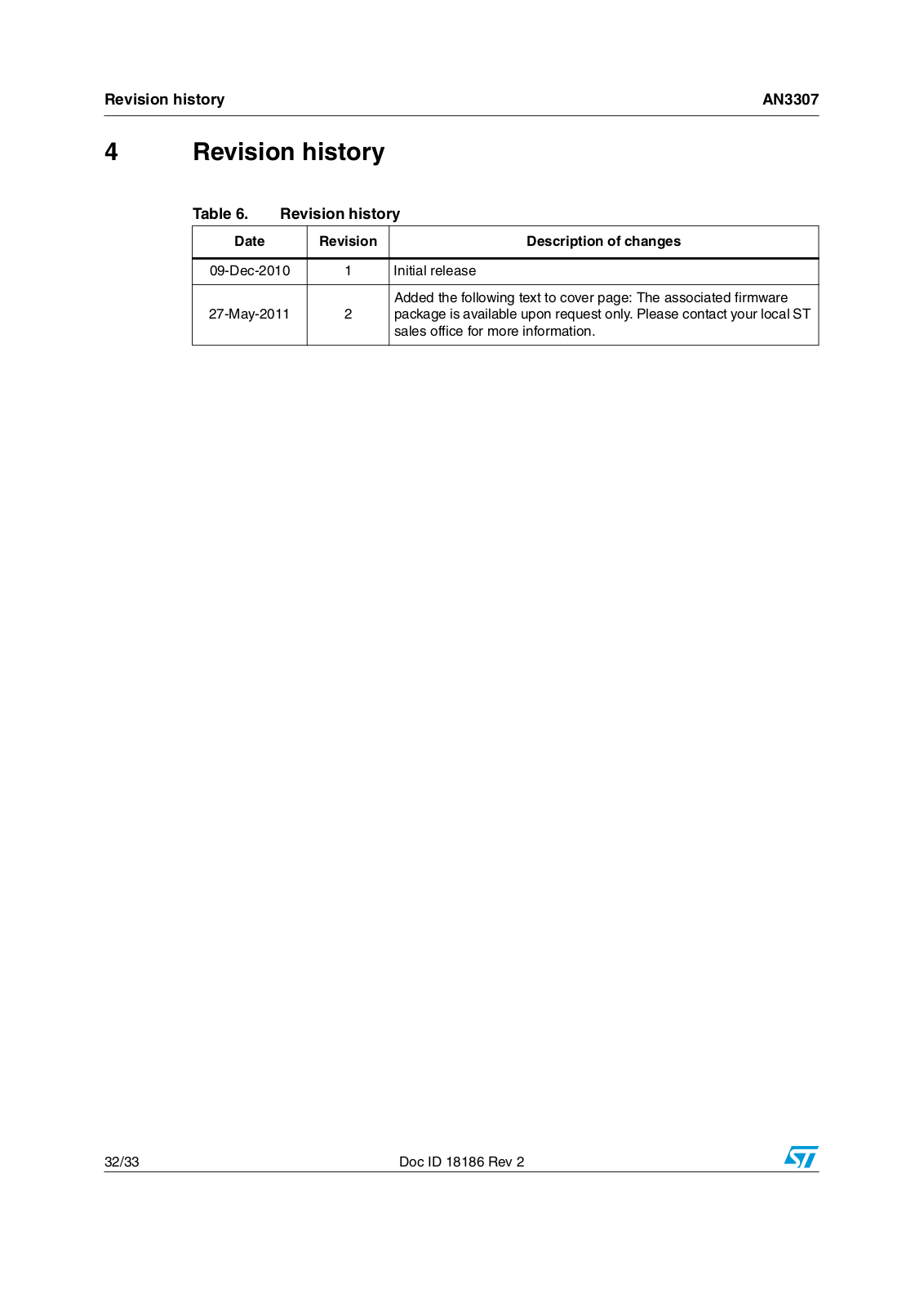
Revision history . . . . . . . . . . . . . . . . . . . . . . . . . . . . . . . . . . . . . . . . . . .

32

Doc ID 18186 Rev 2

3/33

List of tables

AN3307


List of tables

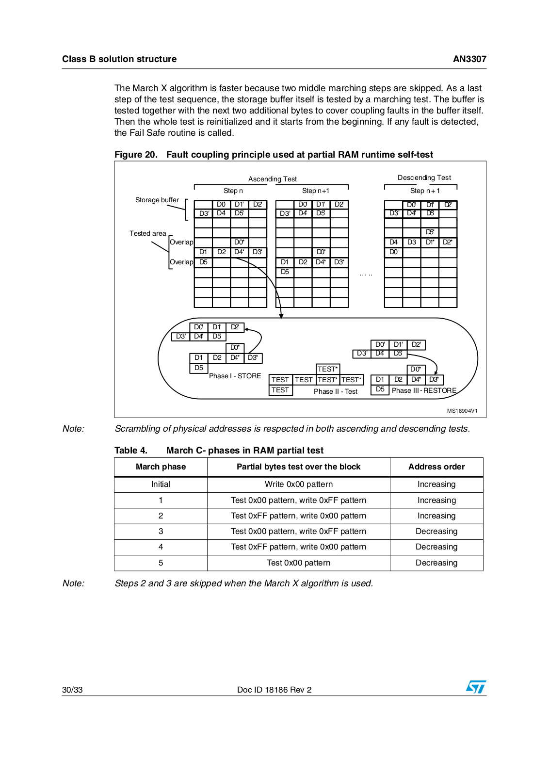
Table 1. MCU parts which must be tested for Class B compliance . . . . . . . . . . . . . . . . . . . . . . . . . . 7 Table 2. Overview of methods used in the micro-specific tests provided with this application note. . 8 Table 3. Physical order of RAM addresses organized into blocks of 16 words . . . . . . . . . . . . . . . . 21 Table 4. March C- phases in RAM partial test . . . . . . . . . . . . . . . . . . . . . . . . . . . . . . . . . . . . . . . . . 30 Table 5. List of self-test library files . . . . . . . . . . . . . . . . . . . . . . . . . . . . . . . . . . . . . . . . . . . . . . . . . 31 Table 6. Revision history . . . . . . . . . . . . . . . . . . . . . . . . . . . . . . . . . . . . . . . . . . . . . . . . . . . . . . . . . 32

4/33

Doc ID 18186 Rev 2

AN3307

List of figures


List of figures

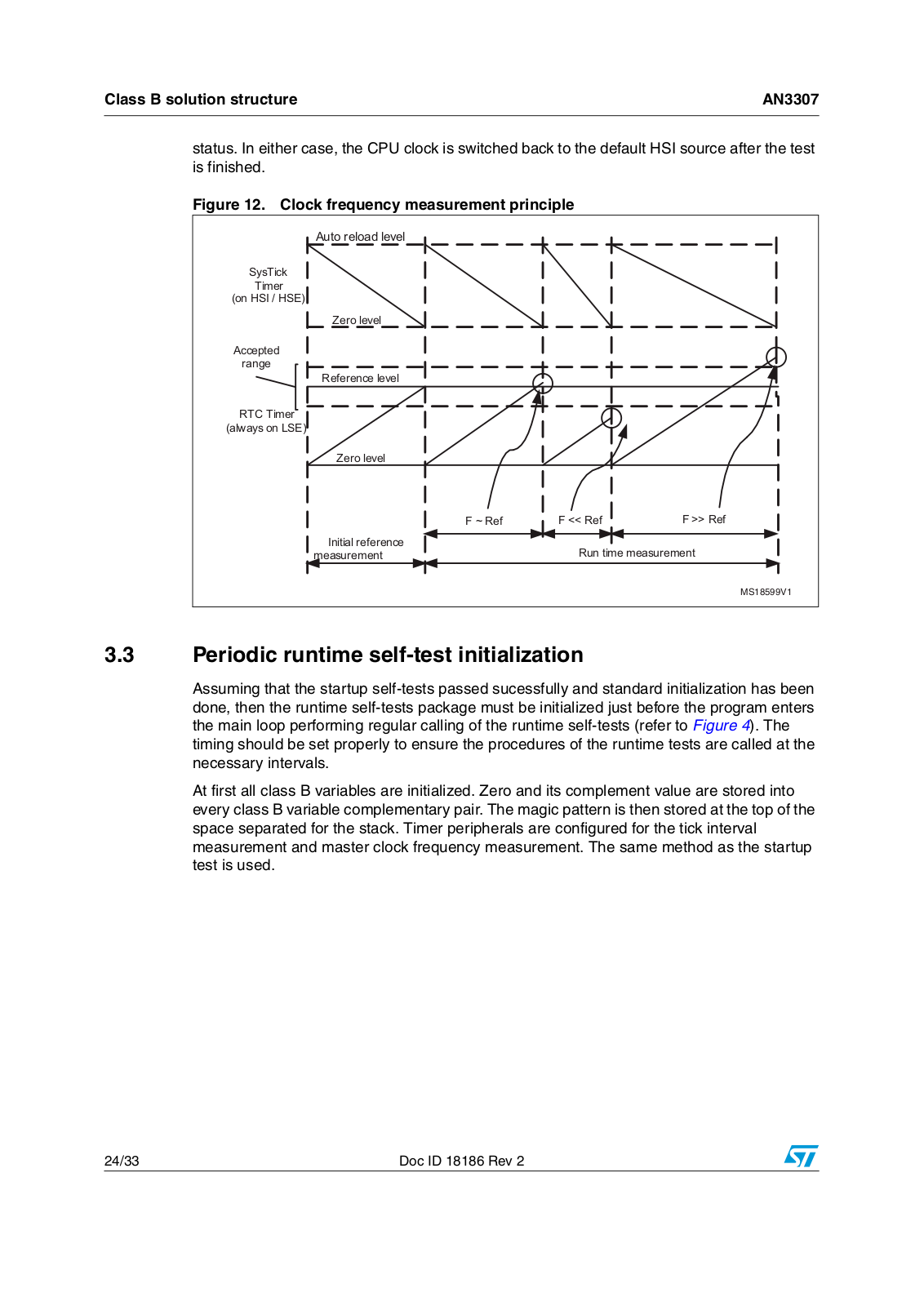
Figure 1. Example of RAM memory configuration . . . . . . . . . . . . . . . . . . . . . . . . . . . . . . . . . . . . . . . 11 Figure 2. Control flow four-step checking principle . . . . . . . . . . . . . . . . . . . . . . . . . . . . . . . . . . . . . . 12 Figure 3. STM32 demo hyper terminal output window in verbose mode. . . . . . . . . . . . . . . . . . . . . . 15 Figure 4. Integration of startup and periodic runtime self-tests into the application. . . . . . . . . . . . . . 17 Figure 5. Startup self tests structure . . . . . . . . . . . . . . . . . . . . . . . . . . . . . . . . . . . . . . . . . . . . . . . . . 18 Figure 6. CPU startup self-test structure . . . . . . . . . . . . . . . . . . . . . . . . . . . . . . . . . . . . . . . . . . . . . . 19 Figure 7. Watchdog startup self-test structure . . . . . . . . . . . . . . . . . . . . . . . . . . . . . . . . . . . . . . . . . . 20 Figure 8. Flash startup self-test structure . . . . . . . . . . . . . . . . . . . . . . . . . . . . . . . . . . . . . . . . . . . . . 21 Figure 9. RAM startup self-test structure . . . . . . . . . . . . . . . . . . . . . . . . . . . . . . . . . . . . . . . . . . . . . . 22 Figure 10. Scramble test - detailed structure of a single check and fill procedure. . . . . . . . . . . . . . . . 22 Figure 11. Clock startup self-test subroutine structure . . . . . . . . . . . . . . . . . . . . . . . . . . . . . . . . . . . . 23 Figure 12. Clock frequency measurement principle. . . . . . . . . . . . . . . . . . . . . . . . . . . . . . . . . . . . . . . 24 Figure 13. Periodic runtime self-test initialization structure . . . . . . . . . . . . . . . . . . . . . . . . . . . . . . . . . 25 Figure 14. Periodic runtime self-test and timebase interrupt service structure . . . . . . . . . . . . . . . . . . 26 Figure 15. CPU light runtime self-test structure . . . . . . . . . . . . . . . . . . . . . . . . . . . . . . . . . . . . . . . . . . 27 Figure 16. Stack overflow runtime test structure . . . . . . . . . . . . . . . . . . . . . . . . . . . . . . . . . . . . . . . . . 27 Figure 17. Clock runtime self-test structure . . . . . . . . . . . . . . . . . . . . . . . . . . . . . . . . . . . . . . . . . . . . . 28 Figure 18. Partial Flash CRC runtime self-test structure . . . . . . . . . . . . . . . . . . . . . . . . . . . . . . . . . . . 28 Figure 19. Partial RAM runtime self-test structure . . . . . . . . . . . . . . . . . . . . . . . . . . . . . . . . . . . . . . . . 29 Figure 20. Fault coupling principle used at partial RAM runtime self-test . . . . . . . . . . . . . . . . . . . . . . 30

Doc ID 18186 Rev 2

5/33

Compliance with IEC and VDE standards

AN3307


1 Compliance with IEC and VDE standards

The IEC (International Electro technical Commission) is a non-profit and non-governmental authority recognized worldwide for preparing and publishing international standards for a vast range of electrical, electronic and related technologies. IEC standards are focused mainly on safety and performance, the environment, electrical energy efficiency and its renewable capabilities. The IEC cooperates closely with ISO (International Organization for Standardization) and ITU (International Telecommunication Union). Their standards define not only the recommendations for hardware, but also for software solutions. Standards are divided into a number of safety classes depending on the purpose of the application.

The other bodies that are recognized worldwide in the field of electronic standard organizations are VDE in Germany, IET in the United Kingdom and the IEEE in the United States. The VDE association also includes a Testing and Certification Institute which is a pioneer of software safety inspection. This is a registered National Certification Body (NCB) for Germany. The main purpose of this testing house is to offer standards compliance and quality testing services to manufacturers of electrical appliances.

One of the pivotal IEC standards is the IEC 60335-1 norm, which covers safety and security of household electronic appliances destined for domestic and similar environment. Appliances incorporating electronic circuits are subject to component failure tests.

The basic principle is that the appliance must remain safe in the case of any component failure. The microcontroller is an electronic component just like any other from this point of view. If safety relies on an electronic component, it must remain safe after two consecutive faults. This means the appliance must stay safe with one hardware failure and with the microcontroller not operating (under reset or not operating properly).

If the safety depends on software, the software is taken into account with the second applied failure. The conditions required for software are defined precisely in Annex Q of the IEC 60335-1 norm. Three classes of appliances are defined here:

Class A: Safety does not rely on software

Class B: Software prevents unsafe operation

Class C: Software is intended to prevent special hazards

This application note and the associated ST software package covers the group B specification. Appliances under group C need some other special requirements such as dual microcontroller operation, which is outside the scope of this document.

Class B compliance aspects for microcontrollers are related both to hardware and software. A list of microcontroller parts under compliance is evaluated at IEC 60335-1 Annex T which refers to IEC60730 Annex H. This list can be divided into two groups - micro-specific and application-specific items. See Table 1.

While application-specific parts rely on customer application structure and must be defined and developed by users (communication, I/O control, interrupts, analog inputs and outputs), micro-specific parts are related purely to the micro structure and can be made generic (core self-diagnostic, volatile and non-volatile memory integrity checking, clock system tests). This group of micro-specific tests is the focus of the ST solution based on powerful hardware features of STM32 MCU such as dual independent watchdogs or clock sources.

6/33

Doc ID 18186 Rev 2

AN3307


Compliance with IEC and VDE standards


Table 1.

MCU parts which must be tested for Class B compliance


Group

Components to be tested


CPU registers


CPU program counter


Micro-specific

Clock


Volatile & non-volatile memories


Internal addressing (and external memory addressing if any)


Internal data path


Interrupt handling


External communication


Application-specific

Timing


I/O peripherals


Analog A/D and D/A


Analog multiplexer


1.1Generic tests included in the STM32F1xx firmware library

The certified by VDE STM32F1xx firmware library packages are composed of the following micro-specific software modules:

CPU register test

Clock monitoring

RAM functional check

Flash checksum integrity check

Watchdog self-test

Stack overflow monitoring

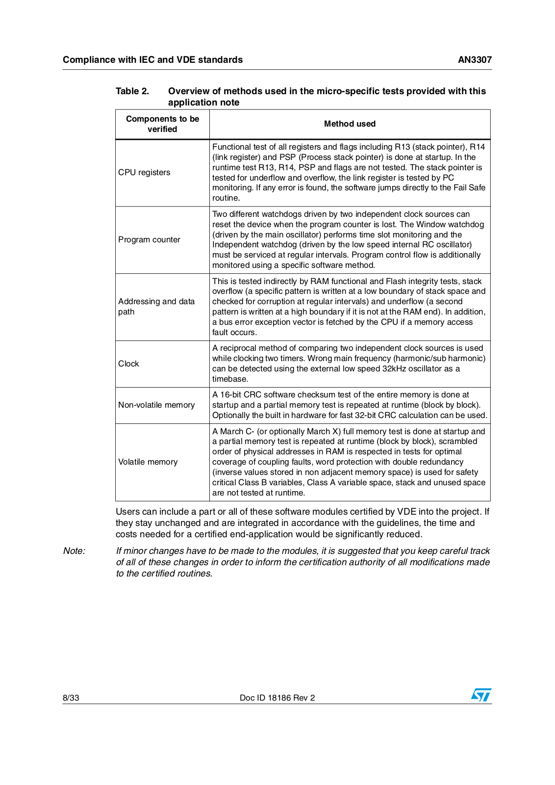
An overview of the methods used for these MCU-specific tests is given in Table 2 and they are described in more detail in the following chapters. The last two items are not explicitly asked for by the norm, but they improve overall fault coverage.

Doc ID 18186 Rev 2

7/33

Compliance with IEC and VDE standards

AN3307


Table 2.

Overview of methods used in the micro-specific tests provided with this


application note


Components to be

Method used


verified


Functional test of all registers and flags including R13 (stack pointer), R14


(link register) and PSP (Process stack pointer) is done at startup. In the


CPU registers

runtime test R13, R14, PSP and flags are not tested. The stack pointer is


tested for underflow and overflow, the link register is tested by PC


monitoring. If any error is found, the software jumps directly to the Fail Safe


routine.


Two different watchdogs driven by two independent clock sources can


reset the device when the program counter is lost. The Window watchdog


Program counter

(driven by the main oscillator) performs time slot monitoring and the


Independent watchdog (driven by the low speed internal RC oscillator)


must be serviced at regular intervals. Program control flow is additionally


monitored using a specific software method.


This is tested indirectly by RAM functional and Flash integrity tests, stack


overflow (a specific pattern is written at a low boundary of stack space and


Addressing and data

checked for corruption at regular intervals) and underflow (a second


path


pattern is written at a high boundary if it is not at the RAM end). In addition,


a bus error exception vector is fetched by the CPU if a memory access


fault occurs.


A reciprocal method of comparing two independent clock sources is used


Clock


while clocking two timers. Wrong main frequency (harmonic/sub harmonic)


can be detected using the external low speed 32kHz oscillator as a


timebase.


A 16-bit CRC software checksum test of the entire memory is done at


Non-volatile memory

startup and a partial memory test is repeated at runtime (block by block).


Optionally the built in hardware for fast 32-bit CRC calculation can be used.


A March C- (or optionally March X) full memory test is done at startup and


a partial memory test is repeated at runtime (block by block), scrambled


order of physical addresses in RAM is respected in tests for optimal


Volatile memory

coverage of coupling faults, word protection with double redundancy


(inverse values stored in non adjacent memory space) is used for safety


critical Class B variables, Class A variable space, stack and unused space


are not tested at runtime.


Users can include a part or all of these software modules certified by VDE into the project. If


they stay unchanged and are integrated in accordance with the guidelines, the time and


costs needed for a certified end-application would be significantly reduced.


Note:

If minor changes have to be made to the modules, it is suggested that you keep careful track


of all of these changes in order to inform the certification authority of all modifications made


to the certified routines.


8/33

Doc ID 18186 Rev 2

AN3307

Compliance with IEC and VDE standards


1.2Application-specific tests not included in the ST firmware library

Users have to focus on all the remaining tests that cover application-specific MCU parts that are not included in the ST firmware library:

Testing the analog blocks (AD/DA, multiplexer)

Testing the digital I/O

External Addressing

External communication

Timing and interrupts

The tests for the analog part depend on the application and peripheral capability of the device. The pins used should be checked for correct analog intervals (by checking that the measured voltages correspond to the real analog values) and free analog pins can be used to read some reference voltages in conjunction with testing the analog multiplexers if they are used in the application. The internal reference voltage should also be checked. Some STM32 devices feature two (and some even three) independent ADC blocks. It make sense to perform conversions on the same channel using two different ADC blocks for security reasons.

Class B tests must also detect any malfunction of the digital I/Os. This could be covered by plausibility checks together with some other application parts (for example, the change in an analog signal from a temperature sensor should be checked when the heating/cooling digital control is switched on/off). Selected port bits can be locked by applying the correct lock sequence to the lock bit in the GPIOx_LCKR register to prevent unexpected changes to the port configuration. Reconfiguration is only possible at the next reset sequence in this case. In addition, the bit banding feature can be used for atomic manipulation of the SRAM and peripheral registers.

Application interrupt occurrences and external communication flows should also be checked. Different methods can be used: one method can use a set of incremental counters with specific counters incremented by each interrupt or communication event. The values in the counters are then checked periodically at given time intervals to make a cross-check with an independent timebase. The number of events performed within the last period should correspond to the application requirements. The configuration lock feature can be used to secure the timer register settings with three levels controlled by the TIMx_BDTR register.

Doc ID 18186 Rev 2

9/33

Class B software package

AN3307


2 Class B software package

This section highlights the basic common principles used in the ST software solution. The workspace organization is described as well as configuration and debugging capabilities. Any differences between the two supported development environments (IAR’s EWARM and Keil’s MDK-ARM) are highlighted.

2.1Basic software principles used

The basic software methods and common principles used for all the tests included in the ST solution are described in detail in this section.

2.1.1Fail Safe mode

If any failure is detected, the FailSafePOR() routine is called (defined in stm32f10x_STLstartup.c file). The program stays in an endless loop waiting for a watchdog reset. Apart from some debugging features the routine is almost empty. Users have to provide the content to the routine and ensure that it executes the right actions to keep the application in a safe state.

The debug or verbose mode described in Section 2.3: Package configuration and debugging can be used to identify which error has occurred.

2.1.2Class B variables

Each class B variable is stored as a pair of two complementary values in two separate RAM regions. Both normal and redundant complementary values are always placed in non adjacent memory locations. A partial transparent RAM March C- or March X test is performed continuously on these RAM areas by means of an interrupt subroutine. The pair is compared for integrity each time before the value is used. If any value stored in the pair is corrupted, Fail Safe mode is invoked. An example of RAM configuration can be seen in Figure 1. Users can adapt the RAM space allocation according to the application needs and the hardware capabilities of the device.

10/33

Doc ID 18186 Rev 2

Loading...
+ 23 hidden pages