How it Works
Log In / Sign Up
Buy Points
How it Works
FAQ
Contact Us
Questions and Suggestions
Users
Datasheet
Loading...
A
AN2393
AN2394
AN2399
AN2400
AN2405
AN2406
AN2407
AN241
AN2415
AN2419
AN2422
AN2423
AN2424
AN2426
AN2430
AN2432
AN2435
AN2439
AN2441
AN2442
AN2443
AN2446
AN2448
AN2450
AN2451
AN2452
AN2454
AN2455
AN2456
AN2458SH
AN2459
AN2466
AN247
AN2470
AN2471
AN2472
AN2474
AN2475
AN2476
AN2479
AN248
AN2483
AN2484
AN2485
AN2487
AN249
AN2491
AN2492
AN2492FH
AN2493FH
AN2495
AN2499
AN250
AN2500
AN2501
AN2502
AN2503
AN2507
AN2509
AN251
AN2510
AN2511
AN2512
AN2515S
AN2516S
AN2521
AN2524
AN2526
AN2528
AN253
AN2530
AN2531
2
AN254
AN2540
AN2544
AN2548
AN2549
AN255
AN2551
AN2555
AN2556
AN2557
AN2559
AN256
AN2565
AN2566
AN2579
AN2583
2
AN2590
AN2591
AN2592
AN2593
AN2594
AN2595
AN2598
AN2604
AN2606
AN2614
AN2615
AN2618
Loading...
Loading...
Nothing found
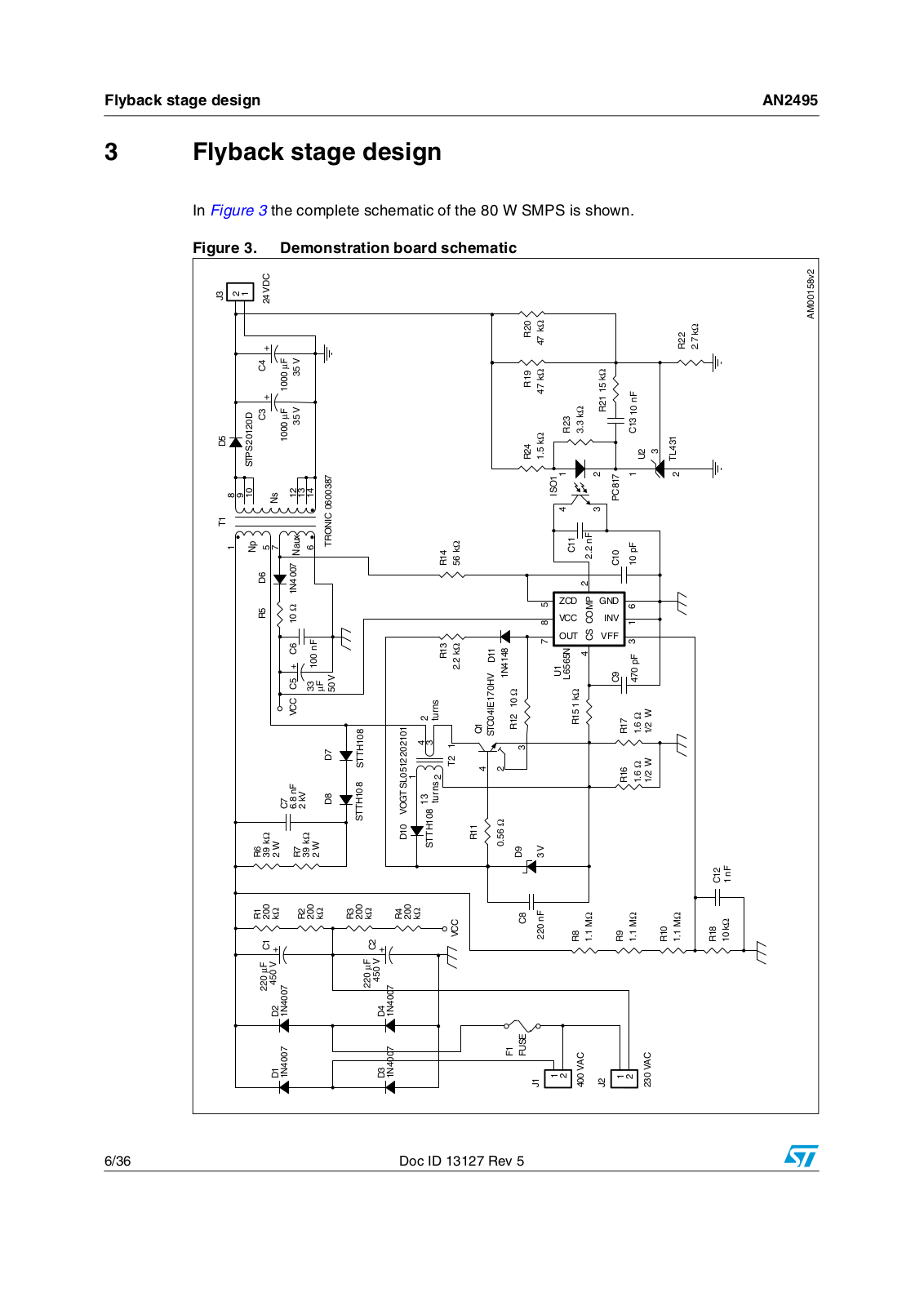
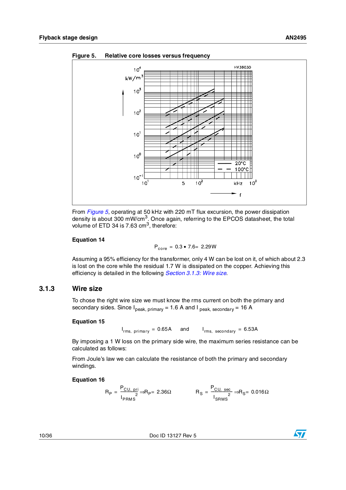
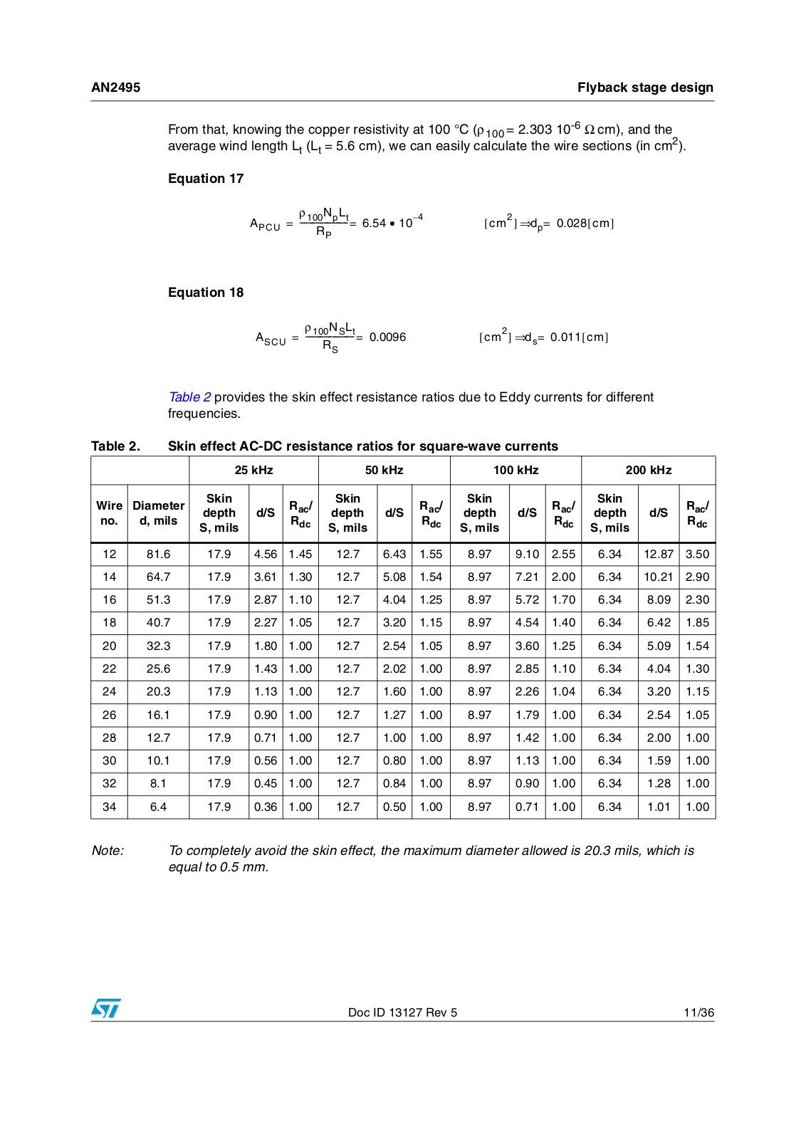
AN2495
APPLICATION NOTE (ST)
36 pgs
826.49 Kb
0
Table of contents
Loading...
Datasheet AN2495 APPLICATION NOTE (ST)
...
Datasheet APPLICATION NOTE (ST)
Download
Specifications and Main Features
Frequently Asked Questions
User Manual
Download
Page 1
Page 2
Page 3
Page 4
Page 5
Page 6
Page 7
Page 8
Page 9
Page 10
Page 11
Page 12
Page 13
Page 14
Page 15
Page 16
Page 17
Page 18
Page 19
Page 20
Page 21
Page 22
Page 23
Page 24
Page 25
Page 26
Page 27
Page 28
Page 29
Page 30
Page 31
Page 32
Page 33
Page 34
Page 35
Page 36
Loading...
+
hidden pages
Unhide
You need points to download manuals.
1 point = 1 manual.
You can buy points or you can get point for every manual you upload.
Buy points
Upload your manuals


")