

Page 1

AN2491
Application note
STW8110x hardware component layer API guide
Introduction
Purpose and scope
This document describes the HCL elements of the STW8110x HCL API included in the
STW8110x evaluation kit. This document is intended for people using the STW8110x digital
bus interfaces. It proposes an abstraction of the hardware in order to allow a user to use all
the facilities provided by the HW IP.
The document provides:
■ A brief description of the hardware
■ An overview of concepts on which the STW8110x HCL API is based
■ A description and explanation of all API types and functions
■ A user scenario
■ The public header file
HCL API version
■ Version of the STW8110x HCL API: V1.0
■ Applicable to the IC: STW8110x
August 2007 Rev 1 1/32
www.st.com
Page 2

Contents AN2491
Contents
1 STW8110x API package . . . . . . . . . . . . . . . . . . . . . . . . . . . . . . . . . . . . . . 4
1.1 Content . . . . . . . . . . . . . . . . . . . . . . . . . . . . . . . . . . . . . . . . . . . . . . . . . . . . 4
1.1.1 Digital bus interface header file . . . . . . . . . . . . . . . . . . . . . . . . . . . . . . . . 4
1.1.2 STW8110x API header file . . . . . . . . . . . . . . . . . . . . . . . . . . . . . . . . . . . 5
1.1.3 STW8110x API source file . . . . . . . . . . . . . . . . . . . . . . . . . . . . . . . . . . . . 5
1.2 How to use the STW8 1 10 x A P I . . . . . . . . . . . . . . . . . . . . . . . . . . . . . . . . . 5
2 API overview . . . . . . . . . . . . . . . . . . . . . . . . . . . . . . . . . . . . . . . . . . . . . . . 6
2.1 Global initialization functions . . . . . . . . . . . . . . . . . . . . . . . . . . . . . . . . . . . 6
2.2 Configuration functions . . . . . . . . . . . . . . . . . . . . . . . . . . . . . . . . . . . . . . . . 6
2.3 Data extraction functions . . . . . . . . . . . . . . . . . . . . . . . . . . . . . . . . . . . . . . 6
2.4 Debug management functions . . . . . . . . . . . . . . . . . . . . . . . . . . . . . . . . . . 6
2.5 Driv e r targets and compilation options . . . . . . . . . . . . . . . . . . . . . . . . . . . . 7
3 Constants and enums . . . . . . . . . . . . . . . . . . . . . . . . . . . . . . . . . . . . . . . . 8
3.1 Both modes . . . . . . . . . . . . . . . . . . . . . . . . . . . . . . . . . . . . . . . . . . . . . . . . 8
2
3.2 I
C mode . . . . . . . . . . . . . . . . . . . . . . . . . . . . . . . . . . . . . . . . . . . . . . . . . 10
4 Structures . . . . . . . . . . . . . . . . . . . . . . . . . . . . . . . . . . . . . . . . . . . . . . . . 11
4.1 Both modes . . . . . . . . . . . . . . . . . . . . . . . . . . . . . . . . . . . . . . . . . . . . . . . 11
2
4.2 I
C mode . . . . . . . . . . . . . . . . . . . . . . . . . . . . . . . . . . . . . . . . . . . . . . . . . 12
5 Functions . . . . . . . . . . . . . . . . . . . . . . . . . . . . . . . . . . . . . . . . . . . . . . . . . 13
5.1 Both modes . . . . . . . . . . . . . . . . . . . . . . . . . . . . . . . . . . . . . . . . . . . . . . . 13
5.2 I2C mode . . . . . . . . . . . . . . . . . . . . . . . . . . . . . . . . . . . . . . . . . . . . . . . . . 17
6 User scenarios . . . . . . . . . . . . . . . . . . . . . . . . . . . . . . . . . . . . . . . . . . . . . 18
6.1 I2C mode . . . . . . . . . . . . . . . . . . . . . . . . . . . . . . . . . . . . . . . . . . . . . . . . . 18
6.2 SPI mode . . . . . . . . . . . . . . . . . . . . . . . . . . . . . . . . . . . . . . . . . . . . . . . . . 20
7 STW8110x public header file . . . . . . . . . . . . . . . . . . . . . . . . . . . . . . . . . 21
8 Digital_Bus_interface header file . . . . . . . . . . . . . . . . . . . . . . . . . . . . . . 29
2/32
Page 3

AN2491 Contents
9 Definitions . . . . . . . . . . . . . . . . . . . . . . . . . . . . . . . . . . . . . . . . . . . . . . . . 30
10 Revision history . . . . . . . . . . . . . . . . . . . . . . . . . . . . . . . . . . . . . . . . . . . 30
3/32
Page 4

List of functions, constants, enums and structures AN2491
List of functions, constants, enums and structures
Configure_STW8110x() . . . . . . . . . . . . . . . . . . . . . . . . . . . . . . . . . . . . . . . . . . . . . . . . . . . 14
I2C_Read_Status_Register() . . . . . . . . . . . . . . . . . . . . . . . . . . . . . . . . . . . . . . . . . . . . . . . 17
STW8110x_Check_config() . . . . . . . . . . . . . . . . . . . . . . . . . . . . . . . . . . . . . . . . . . . . . . . . 15
STW8110x_Get_Fout_value() . . . . . . . . . . . . . . . . . . . . . . . . . . . . . . . . . . . . . . . . . . . . . . 16
STW8110x_Init(). . . . . . . . . . . . . . . . . . . . . . . . . . . . . . . . . . . . . . . . . . . . . . . . . . . . . . . . . 13
STW8110x_ProcessError(). . . . . . . . . . . . . . . . . . . . . . . . . . . . . . . . . . . . . . . . . . . . . . . . . 16
t_CP_SEL. . . . . . . . . . . . . . . . . . . . . . . . . . . . . . . . . . . . . . . . . . . . . . . . . . . . . . . . . . . . . . . 8
t_PD . . . . . . . . . . . . . . . . . . . . . . . . . . . . . . . . . . . . . . . . . . . . . . . . . . . . . . . . . . . . . . . . . . . 8
t_PLL_A . . . . . . . . . . . . . . . . . . . . . . . . . . . . . . . . . . . . . . . . . . . . . . . . . . . . . . . . . . . . . . . . 9
t_PSC_SEL. . . . . . . . . . . . . . . . . . . . . . . . . . . . . . . . . . . . . . . . . . . . . . . . . . . . . . . . . . . . . . 9
t_SERCAL . . . . . . . . . . . . . . . . . . . . . . . . . . . . . . . . . . . . . . . . . . . . . . . . . . . . . . . . . . . . . . 8
t_stw8110x_Config . . . . . . . . . . . . . . . . . . . . . . . . . . . . . . . . . . . . . . . . . . . . . . . . . . . . . . . 11
t_stw8110x_Device_Type. . . . . . . . . . . . . . . . . . . . . . . . . . . . . . . . . . . . . . . . . . . . . . . . . . 10
t_stw8110x_error . . . . . . . . . . . . . . . . . . . . . . . . . . . . . . . . . . . . . . . . . . . . . . . . . . . . . . . . . 9
t_stw8110x_I2C_RO_reg . . . . . . . . . . . . . . . . . . . . . . . . . . . . . . . . . . . . . . . . . . . . . . . . . . 12
t_stw8110x_PLL_Status. . . . . . . . . . . . . . . . . . . . . . . . . . . . . . . . . . . . . . . . . . . . . . . . . . . 10
t_stw8110x_Registers . . . . . . . . . . . . . . . . . . . . . . . . . . . . . . . . . . . . . . . . . . . . . . . . . . . . 11
4/32
Page 5
AN2491 STW8110x API package
1 STW8110x API package
It is highly recommended to read the STW81101, STW81102 or STW81103 datasheet
before continuing to read this document. This API is a simple abstraction of the principles
presented in these datasheet s.
The STW8110x device has two embedded digital bus interfaces (I
their internal registers to be programmed. Each of these interfaces has its own dedicated
protocol which must be followed to program the device correctly. For details of the
STW8110x register and SPI and I
1.1 Content
2
C protocols, refer to the relevant datasheet.
2
C and SPI) which allow
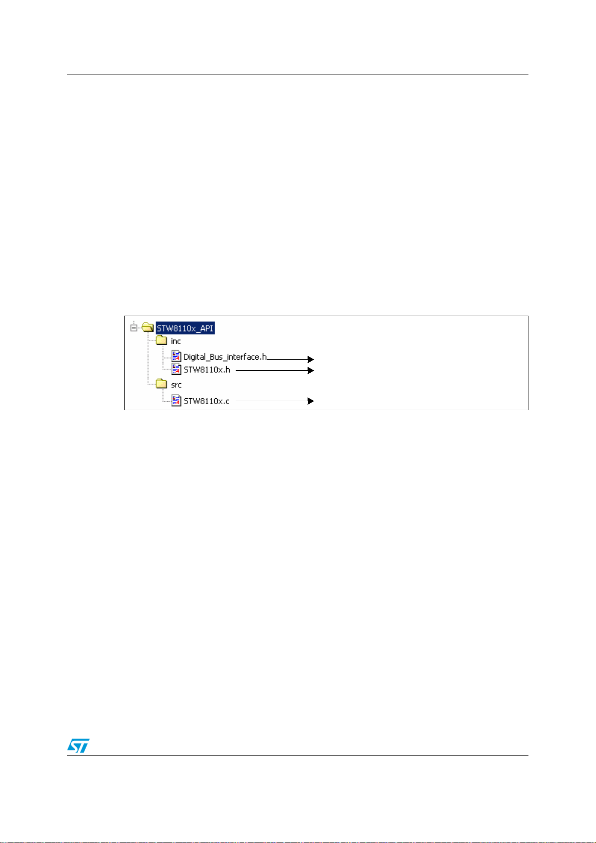
Three files are available in this package. A fourth file must be created by the user with
implementation of I
Figure 1. Files available with this package
2
C and SPI functions according to the master interface.
1.1.1 Digital bus interface header file
Contains declarations of functions to be implemented by the user (refer to
complete listing). This subsection describes the tasks that the functions must accomplish.
For more details about the digital bus protocol flow and configuration to apply to your master
interface (as frequency) please refer to the STW81101, STW81102 or STW81103
datasheet.
I2C mode
t_I2C_Ack I2C_Send_data(unsigned char *data, int nb_bytes)
{
// 1 - Send Start Bit
// 2 - loop i=1 to i=nb_bytes
// a - send data[i]
// b - wait acknowledge of slave
// 3 - Send Stop Bit
// return ACK, or NO_ACK if acknowledge hasn’t been received
}
1. Digital bus interface header file
2. STW8110x API header file
3. STW8110x API source file
Section 8
for a
t_I2C_Ack I2C_Read_data(unsigned char Add, unsigned char *data)
{
// 1 - Send Start Bit
// 2 - send Add
// 3 - wait acknowledge of slave
5/32
Page 6

STW8110x API package AN2491
// 4 - read received data and affect it to *data
// 3 - Send Stop Bit
// return ACK, or NO_ACK if acknowledge hasn’t been received
}
SPI mode
void SPI_Send_data(unsigned int data)
{
// Send data (32bits) on SPI bus
}
1.1.2 STW8110x API header file
Contains declaration of functions, structures and defines necessary to the device driver.
(Refer to
Section 7
for a complete listing).
1.1.3 STW8110x API source file
Contains the C code of device driver.
1.2 How to use the STW8110x API
1. Add the API in your project (STW8110x.c, STW8110x.h, Digital_Bus_interface.h).
2. Create a file (Digital_Bus_interface.c) with functions to implement according your
master interface.
3. Include the STW8110x header file (#include “STW8110x.h”) in the file which uses the
API functions.
4. Use dedicated functions to program the device (see examples in
Section 6
).
6/32
Page 7

AN2491 API overview
2 API overview
Note: To ensure the correct usage of this HCL API, it is HIGHLY recommended to use this API in
the debug mode first (by use of __DEBUG preprocessor as described in Section 2.5). Only
after the application has executed successfully in debug mode should the STW8110x driver
be run in release mode.
The API contains 4 types of functions:
● Functions related to the global initialization of STW8110x
● Functions related to the configuration of STW8110x
● Functions related to extraction of the STW8110x configuration information
● Functions related to STW8110x debug management
2.1 Global initialization functions
STW8110x_Init(); initializes the data structures of the STW8110x HCL.
2.2 Configuration functions
Configure_STW8110x(); configures the STW8110x device.
2.3 Data extraction functions
● STW8110x_Check_config(); verifies selected configuration.
● STW8110x_Get_Fout_value(); gets output frequency according selected configuration.
● I2C_Read_Status_Register(); obtains information about read-only register (I
2.4 Debug management functions
STW8110x_ProcessError (); manages possible errors of the STW8110x device driver.
2
C mode).
7/32
Page 8
API overview AN2491
2.5 Driver targets and compilation options
The driver source files can work in several environments. There are three possible targets
for which the driver compilation options (#define) customize the code for the target.
● The platform - represents the IC (STW81101, STW81102, STW81103).
● The interface - represents digital interface used to program the device (I
● The mode - identifies if the code is being compiled for debug or release mode.
Table 1. Target platform compilation options
Platform STW81101 STW81102 STW81103
#define __PLATFORM_STW81101 __PLATFORM_STW81102 __PLATFORM_STW81103
Table 2. Target interface compilation options
Interface I2C SPI
#define __INTERFACE_I2C __INTERFACE_SPI
Table 3. Target mode compilation options
Mode Debug Release
2
C, SPI ).
#define __DEBUG __NO_DEBUG
8/32
Page 9

AN2491 Constants and enums
3 Constants and enums
3.1 Both modes
t_PD
Defines the device functional mode.
typedef enum
{
POWER_DOWN,
VCO_A_FREQ_DIV_2,
VCO_B_FREQ_DIV_2,
VCO_EXT_FREQ_DIV_2,
VCO_A_FREQ_DIV_4,
VCO_B_FREQ_DIV_4,
VCO_EXT_FREQ_DIV_4,
VCO_A_DIRECT_OUTPUT,
VCO_B_DIRECT_OUTPUT,
VCO_EXT_DIRECT_OUTPUT
} t_PD;
t_SERCAL
Defines the VCO auto-ca libration status.
typedef enum
{
VCO_CAL_DISABLED,
VCO_CAL_ENABLED
} t_SERCAL;
t_CP_SEL
Defines the charge pump current
typedef enum
{
CURRENT_I_MIN,
CURRENT_2_I_MIN,
CURRENT_3_I_MIN,
CURRENT_4_I_MIN,
CURRENT_5_I_MIN,
CURRENT_6_I_MIN,
CURRENT_7_I_MIN,
CURRENT_8_I_MIN
} t_CP_SEL;
9/32
Page 10

Constants and enums AN2491
t_PSC_SEL
Defines the prescaler modulus.
typedef enum
{
PRESCALER_16,
PRESCALER_19
} t_PSC_SEL;
t_PLL_A
Defines the PLL amplitude voltage of VCO.
typedef enum
{
AMPL_1V1,
AMPL_1V3,
AMPL_1V9,
AMPL_2V1
} t_PLL_A;
t_stw8110x_error
Defines all errors that can be returned by the functions of the STW8110x HCL API.
typedef enum
{
OK = 0,
ERR_A_HIGHER_THAN_B = -113,
ERR_A_OUTOF_RANGE ,// = -112,
ERR_B_OUTOF_RANGE ,// = -111,
ERR_N_OUTOF_RANGE ,// = -110,
ERR_VCOA_FREQ_OUTOF_RANGE ,// = -109,
ERR_VCOB_FREQ_OUTOF_RANGE ,// = -108,
ERR_FUNCT_MODE_UNKNOWN ,// = -107,
ERR_REF_CLK_DIVIDER ,// = -106,
ERR_PRESCALER ,// = -105,
ERR_VCO_CALIBRATION ,// = -104,
ERR_VCO_VOLTAGE ,// = -103,
#ifdef __INTERFACE_I2C
ERR_I2C_ACK ,// = -102,
ERR_BAD_DEVICE ,// = -101,
ERR_I2C_READ ,// = -100,
#endif //__INTERFACE_I2C
ERR_CHARGE_PUMP_CURRENT // = -99 or -102
} t_stw8110x_error ;
10/32
Page 11

AN2491 Constants and enums
3.2 I2C mode
t_stw8110x_Device_Type
Defines the device name.
typedef enum
{
DEV_STW81101,
DEV_STW81102,
DEV_STW81103
} t_stw8110x_Device_Type ;
t_stw8110x_PLL_Status
Defines the status of PLL.
typedef enum
{
PLL_UNLOCKED,
PLL_LOCKED
} t_stw8110x_PLL_Status ;
11/32
Page 12

Structures AN2491
4 Structures
4.1 Both modes
t_stw8110x_Registers
Defines the structure of STW8110x registers.
typedef struct
{
#ifdef __INTERFACE_I2C
t_uint8 REG0; // Functional modes
t_uint8 REG1; // B counter
t_uint8 REG2; // A counter
t_uint8 REG3; // Reference divider
t_uint8 REG4; // Control
t_uint8 REG5; // Calibration
t_uint8 REGRO; // Read only register: internal calibration of
// VCO, PLL state (locked,unlocked), Device ID
#endif //__INTERFACE_I2C
#ifdef __INTERFACE_SPI
// ST1: reference divider, VCO amplitude, VCO Calibration,
// Charge Pump current, Prescaler Modulus
t_uint32 ST1;
// ST2: Functional modes, VCO dividers
// __INTERFACE_SPI
#endif
t_uint32 ST2;
} t_stw8110x_Registers ;
t_stw8110x_Config
Defines the structure that holds essential transfer parameters for device configuration.
typedef struct
{
t_bool DEFAULT_CONFIG;
t_SERCAL VCO_CALIBRATION_EN;
t_PD DEVICE_FUNCTIONAL_MODE;
t_uint32 MAIN_COUNTER;
t_uint32 SWALLOW_COUNTER;
t_uint32 REF_CLOCK_DIV_RATIO;
t_PLL_A VCO_AMPLITUDE_VOLTAGE;
t_CP_SEL CHARGE_PUMP_CURRENT;
t_PSC_SEL PRESCALER_MODULUS;
} t_stw8110x_Config ;
Note: If the field DEFAULT_CONFIG is marked as BOOL_TRUE then the remaining fields
following it may not be used and may not be filled up. Instead the default configuration for
the device (as programmed in STW8110x_Init) will be used. The default configuration is
described in the STW81101, STW81102 and STW81103 datasheets.
12/32
Page 13

AN2491 Structures
4.2 I2C mode
t_stw8110x_I2C_RO_reg
Defines the structure of STW8110x read-only register.
typedef struct
{
t_stw8110x_Device_Type DEV_TYPE; // Device identifier bit
t_stw8110x_PLL_Status LOCK_DET; // '1' when PLL is locked
t_uint8 INT_CAL; //VCO ctrl word internal value
} t_stw8110x_I2C_RO_reg ;
13/32
Page 14

Functions AN2491
5 Functions
STW8110x has 3 bits which are programmable in I2C mode. This means that eight
STW8110x devices should be connected to the same I
The choice of device is performed via the 3 programmable address bits (A2, A1, A0 set to
0V (0) or 3.3V (1)). This is why, if I
supplementary parameter which specifies the address of the device to access I2C_ADD (0
to 7).
5.1 Both modes
STW8110x_Init()
Description Initializes the STW8110x HCL.
Definition
Arguments
Both modes (out)
2
I
C mode (in)
2
C master.
2
C mode is selected, some functions require a
t_stw8110x_error STW8110x_Init(
t_stw8110x_Config *Device_config_init
#ifdef __INTERFACE_I2C
,t_uint8 I2C_ADD
#endif
);
Device_config_init: Structure containing default config of device
I2C_ADD: Address of STW8110x device (only I2C mode)
Return value t_stw8110x_error
FunctionType Synchronous
Potential errors:
– Both modes:
OK,
2
C modes:
–I
Comments
ERR_BAD_DEVICE,
ERR_I2C_ACK,
ERR_I2C_READ
The routine initializes the device configuration descriptor. If I
selected, a read of the read only register is performed to check if the selected
target matches with the accessed device.
2
C mode is
14/32
Page 15

AN2491 Functions
Configure_STW8110x()
Description Configures the STW8110x device.
t_stw8110x_error Configure_STW8110x(
t_stw8110x_Config Device_config_init
Definition
Arguments
Both modes(out)
2
I
C mode (in)
Return value t_stw8110x_error
FunctionType Synchronous
Comments
#ifdef __INTERFACE_I2C
,t_uint8 I2C_ADD
#endif
);
Device_config_init: Structure containing configuration of device
I2C_ADD: Address of STW8110x device (only I2C mode)
Potential errors:
– Both modes:
OK,
ERR_VCO_CALIBRATION,
ERR_FUNCT_MODE_UNKNOWN,
ERR_VCO_VOLTAGE,
ERR_CHARGE_PUMP_CURRENT,
ERR_PRESCALER,
ERR_A_HIGHER_THAN_B,
ERR_A_OUTOF_RANGE,
ERR_B_OUTOF_RANGE,
ERR_REF_CLK_DIVIDER,
ERR_N_OUTOF_RANGE,
2
–I
C modes:
ERR_I2C_ACK
During this routine, a check of the device configuration (using the
STW8110x_Check_config function) is performed before configuring the
registers.
15/32
Page 16

Functions AN2491
STW8110x_Check_config()
Description Checks the configuration selected with device specification.
t_stw8110x_error STW8110x_Check_config(
Definition
Arguments (in) Device_config: Structure containing configuration of device
Return value t_stw8110x_error
FunctionType Synchronous
Comments
t_stw8110x_Config Device_config
);
Potential errors:
OK,
ERR_VCO_CALIBRATION,
ERR_FUNCT_MODE_UNKNOWN,
ERR_VCO_VOLTAGE,
ERR_CHARGE_PUMP_CURRENT,
ERR_PRESCALER,
ERR_A_HIGHER_THAN_B,
ERR_A_OUTOF_RANGE,
ERR_B_OUTOF_RANGE,
ERR_REF_CLK_DIVIDER,
ERR_N_OUTOF_RANGE
16/32
Page 17

AN2491 Functions
STW8110x_Get_Fout_value()
Description
Definition
Arguments (in)
(in)
(out)
Return value t_stw8110x_error
FunctionType Synchronous
Comments
Returns output frequency according to the selected configuration and the input
frequency.
t_stw8110x_error STW8110x_Get_Fout_value(
t_stw8110x_Config Device_config_init,
double Fref_clk,
double *Fout_MHz
);
Device_config_init: Structure containing configuration of device
Fref_clk: Input frequency in MHz
Fout_MHz: Output frequency in MHz
Potential errors:
OK,
ERR_VCO_CALIBRATION,
ERR_FUNCT_MODE_UNKNOWN,
ERR_VCO_VOLTAGE,
ERR_CHARGE_PUMP_CURRENT,
ERR_PRESCALER,
ERR_A_HIGHER_THAN_B,
ERR_A_OUTOF_RANGE,
ERR_B_OUTOF_RANGE,
ERR_REF_CLK_DIVIDER,
ERR_N_OUTOF_RANGE,
ERR_VCOA_FREQ_OUTOF_RANGE,
ERR_VCOB_FREQ_OUTOF_RANGE
STW8110x_ProcessError()
Description Manages the STW8110x device driver errors.
void STW8110x_ProcessError(
Definition
Arguments (in) error: error returned by functions of API
Return value none
FunctionType Synchronous
t_stw8110x_error error
);
17/32
Page 18

Functions AN2491
5.2 I2C mode
I2C_Read_Status_Register()
Description Returns the value of the STW8110x read only register.
t_stw8110x_error I2C_Read_Status_Register(
Definition
Arguments (out)
(in)
Return value t_stw8110x_error
FunctionType Synchronous
Comments
t_stw8110x_I2C_RO_reg *ReadOnlyReg,
t_uint8 I2C_ADD
);
ReadOnlyReg: Structure containing value of read o nly register
I2C_ADD: Address of the STW8110x device
Potenti al errors:
OK,
ERR_I2C_ACK,
ERR_I2C_READ
18/32
Page 19

AN2491 User scenarios
6 User scenarios
6.1 I2C mode
// Device address define
#define DEVICE_ADD 0x1 // A2=0, A1=0, A0=1
// STW8110x declaration
t_stw8110x_Config Device_config;
t_stw8110x_error st_error;
double Fout;
t_stw8110x_I2C_RO_reg ReadOnlyReg;
// Device Driver Initilization
st_error = STW8110x_Init(&Device_config, DEVICE_ADD);
if(st_error != OK)
{
STW8110x_ProcessError(st_error);
}
//******* Configuration I **********
// Set configuration structure of device
// Default config is selected
Device_config.DEFAULT_CONFIG = BOOL_TRUE;
// Configure the device
st_error = Configure_STW8110x(Device_config, DEVICE_ADD);
if(st_error != OK)
{
STW8110x_ProcessError(st_error);
}
//******* Configuration II **********
// Set configuration structure of device.
// Config is set to ouput frequency 843.75MHz, reference clock 60MHz
Device_config.DEFAULT_CONFIG = BOOL_FALSE;
Device_config.DEVICE_FUNCTIONAL_MODE = VCO_A_FREQ_DIV_4;
Device_config.VCO_CALIBRATION_EN = VCO_CAL_ENABLED;
Device_config.SWALLOW_COUNTER = 8;
Device_config.MAIN_COUNTER = 562;
Device_config.REF_CLOCK_DIV_RATIO = 160;
Device_config.VCO_AMPLITUDE_VOLTAGE = AMPL_2V1;
Device_config.CHARGE_PUMP_CURRENT = CURRENT_8_I_MIN;
Device_config.PRESCALER_MODULUS = PRESCALER_16;
// Configure the device
st_error = Configure_STW8110x(Device_config, DEVICE_ADD);
if(st_error != OK)
{
STW8110x_ProcessError(st_error);
}
// Get output frequency(MHz) according config and reference clock
st_error = STW8110x_Get_Fout_value(Device_config,60,&Fout);
if(st_error != OK)
{
STW8110x_ProcessError(st_error);
19/32
Page 20

User scenarios AN2491
}
printf("With selected configuration and input freq=60MHz, output
Freq = %fMHz\n",Fout);
// Reading Read Only register of device
st_error = I2C_Read_Status_Register(&ReadOnlyReg, DEVICE_ADD);
if(st_error != OK)
{
STW8110x_ProcessError(st_error);
}
printf("Device Read Only Register Status:\n");
printf("Device ID : %d\n", ReadOnlyReg.DEV_TYPE);
printf("PLL: %s\n", (ReadOnlyReg.LOCK_DET)?"Locked":"Unlocked");
printf("Internal VCO value: %d\n", ReadOnlyReg.INT_CAL);
// Note: If you have selected the DEBUG mode, information is
// automatically displayed, so no printf is needed
20/32
Page 21

AN2491 User scenarios
6.2 SPI mode
// STW8110x declaration
t_stw8110x_Config Device_config;
t_stw8110x_error st_error;
double Fout;
// Device Driver Initilization
STW8110x_Init(&Device_config);
//******* Configuration I **********
// Set configuration structure of device
// Config set to ouput frequency 4467.1875MHz reference clock 60MHz
Device_config.DEFAULT_CONFIG = BOOL_FALSE;
Device_config.DEVICE_FUNCTIONAL_MODE = VCO_B_DIRECT_OUTPUT;
Device_config.VCO_CALIBRATION_EN = VCO_CAL_ENABLED;
Device_config.SWALLOW_COUNTER = 11;
Device_config.MAIN_COUNTER = 501;
Device_config.REF_CLOCK_DIV_RATIO = 128;
Device_config.VCO_AMPLITUDE_VOLTAGE = AMPL_2V1;
Device_config.CHARGE_PUMP_CURRENT = CURRENT_8_I_MIN;
Device_config.PRESCALER_MODULUS = PRESCALER_19;
st_error = STW8110x_Get_Fout_value(Device_config,60,&Fout);
if(st_error != OK)
{
STW8110x_ProcessError(st_error);
}
// Configure the device
st_error = Configure_STW8110x(Device_config);
if(st_error != OK)
{
STW8110x_ProcessError(st_error);
}
//******* Config II: Set in Power Down mode **********
// Set configuration structure of device
Device_config.DEFAULT_CONFIG = BOOL_FALSE;
Device_config.DEVICE_FUNCTIONAL_MODE = POWER_DOWN;
// Configure the device
st_error = Configure_STW8110x(Device_config);
if(st_error != OK)
{
STW8110x_ProcessError(st_error);
}
21/32
Page 22

STW8110x public header file AN2491
7 STW8110x public header file
//*****************************************************************
// Copyright (C) 2006 STMicroelectronics
// File name:STW8110x.h
// Description:Header file for SPI/I2C STW8110x Interface Driver
// code. Provides function type and data structure definition
// Creation:11/20/2006
//*****************************************************************
#ifndef _STW8110x_H
#define _STW8110x_H
//*****************************************************************
// -------Preprocessor Checking------//*****************************************************************
#if !( defined(__PLATFORM_STW81101) | defined(__PLATFORM_STW81102)
| defined(__PLATFORM_STW81103))
#error "__PLATFORM_STW81101, __PLATFORM_STW81102 or
__PLATFORM_STW81103 must be defined"
#endif
#if !( defined(__INTERFACE_I2C) | defined(__INTERFACE_SPI))
#error "Either of __INTERFACE_I2C or __INTERFACE_SPI must be
defined"
#endif
#if !( defined(__NO_DEBUG) | defined(__DEBUG))
#error "Either of __NO_DEBUG or __DEBUG must be defined"
#endif
//*****************************************************************
// -------Allowing C++ to use these headers------//*****************************************************************
#ifdef__cplusplus
extern "C" {
#endif // __cplusplus
//*****************************************************************
// -------miscellaneous------//*****************************************************************
//----------------------------------------------------------------// Type definition
//----------------------------------------------------------------typedef unsigned int t_uint32;
typedef unsigned char t_uint8;
//----------------------------------------------------------------// Type enumeration
//----------------------------------------------------------------typedef enum {BOOL_FALSE, BOOL_TRUE} t_bool;
//----------------------------------------------------------------// Constants
//----------------------------------------------------------------#define REG_CLEAR0x00000000
#define ZERO0x0
22/32
Page 23

AN2491 STW8110x public header file
//----------------------------------------------------------------// Macros dedicated to build, set, get bits of registers
//----------------------------------------------------------------#define mREG_SET(__datum, __val) ((__datum) = (t_uint32)(__val))
#define mBYTE_SET(__datum, __val) ((__datum) = (t_uint8)(__val))
#define mBIT_MASK(__bws)
((t_uint32)(((bw##__bws)==32)?0xFFFFFFFF:((1 << (bw##__bws)) - 1))
<< (bs##__bws))
#define mBIT_BUILD(__bws, __val) ((t_uint32)(((t_uint32)(__val) <<
(t_uint32)(bs##__bws)) & ((t_uint32) mBIT_MASK(__bws))))
#define mBIT_GET(__datum, __bws) ((t_uint32)(((__datum) &
((t_uint32) mBIT_MASK(__bws))) >> (bs##__bws)))
#define mBIT_SET(__datum, __bws, __val) ((__datum) = ((t_uint32)
(__datum) & (t_uint32)~(mBIT_MASK(__bws))) | ((t_uint32)
((t_uint32)(__val) << (t_uint32)(bs##__bws)) & (mBIT_MASK(__bws))))
//----------------------------------------------------------------// Macros dedicated to print a string (depends of debug mode)
//----------------------------------------------------------------#ifdef __DEBUG
#include "stdio.h"
#define DBGPRINT(str) printf(str)
#define DBGPRINT1(str,a) printf(str,a)
#define DBGPRINT2(str,a,b) printf(str,a,b)
#define DBGPRINT3(str,a,b,c) printf(str,a,b,c)
#else
#ifdef __NO_DEBUG
#define DBGPRINT(str)
#define DBGPRINT1(str,a)
#define DBGPRINT2(str,a,b)
#define DBGPRINT3(str,a,b,c)
#endif // __NO_DEBUG
#endif //__DEBUG
//*****************************************************************
// -------STW8110x Frequency range------//*****************************************************************
#ifdef __PLATFORM_STW81101
#define VCO_A_FREQ_MIN 3300
#define VCO_A_FREQ_MAX 3900
#define VCO_B_FREQ_MIN 3800
#define VCO_B_FREQ_MAX 4400
#elif __PLATFORM_STW81102
#define VCO_A_FREQ_MIN 3000
#define VCO_A_FREQ_MAX 3620
#define VCO_B_FREQ_MIN 4000
#define VCO_B_FREQ_MAX 4650
#elif __PLATFORM_STW81103
#define VCO_A_FREQ_MIN 2500
#define VCO_A_FREQ_MAX 3050
#define VCO_B_FREQ_MIN 4350
#define VCO_B_FREQ_MAX 5000
#endif
23/32
Page 24

STW8110x public header file AN2491
//*****************************************************************
// -------STW8110x Device Address / access mode------//*****************************************************************
#ifdef __INTERFACE_I2C
#define I2C_DEVICE_MSB_ADD 0xC0
#define I2C_READ 1
#define I2C_WRITE 0
#define REG0_ADD 0x00
#define REG1_ADD 0x01
#define REG2_ADD 0x02
#define REG3_ADD 0x03
#define REG4_ADD 0x04
#define REG5_ADD 0x05
#endif //__INTERFACE_I2C
#ifdef __INTERFACE_SPI
#define ST1_ADD 0x00
#define ST2_ADD 0x01
#define SHIFT_ADD 24
#endif //__INTERFACE_SPI
//*****************************************************************
// -------STW8110x Enumeration Types------//*****************************************************************
// STW8110x errors
typedef enum
{
OK = 0,
ERR_A_HIGHER_THAN_B = -113,
ERR_A_OUTOF_RANGE ,// = -112,
ERR_B_OUTOF_RANGE ,// = -111,
ERR_N_OUTOF_RANGE ,// = -110,
ERR_VCOA_FREQ_OUTOF_RANGE ,// = -109,
ERR_VCOB_FREQ_OUTOF_RANGE ,// = -108,
ERR_FUNCT_MODE_UNKNOWN ,// = -107,
ERR_REF_CLK_DIVIDER ,// = -106,
ERR_PRESCALER ,// = -105,
ERR_VCO_CALIBRATION ,// = -104,
ERR_VCO_VOLTAGE ,// = -103,
#ifdef __INTERFACE_I2C
ERR_I2C_ACK ,// = -102,
ERR_BAD_DEVICE ,// = -101,
ERR_I2C_READ ,// = -100,
#endif //__INTERFACE_I2C
ERR_CHARGE_PUMP_CURRENT // = -99 or -102
} t_stw8110x_error ;
//
// Prescaler modulus definition
//
typedef enum {
PRESCALER_16,
PRESCALER_19
} t_PSC_SEL;
24/32
Page 25

AN2491 STW8110x public header file
//
// VCO calibration enabling definition
//
typedef enum {
VCO_CAL_DISABLED,
VCO_CAL_ENABLED
} t_SERCAL;
//
// Device Functional modes definition
//
typedef enum {
CURRENT_I_MIN,
CURRENT_2_I_MIN,
CURRENT_3_I_MIN,
CURRENT_4_I_MIN,
CURRENT_5_I_MIN,
CURRENT_6_I_MIN,
CURRENT_7_I_MIN,
CURRENT_8_I_MIN
} t_CP_SEL;
//
//VCO Voltage Amplitude definition
//
typedef enum {
AMPL_1V1,
AMPL_1V3,
AMPL_1V9,
AMPL_2V1
} t_PLL_A;
//
// Device Functional modes definition
//
typedef enum {
POWER_DOWN,
VCO_A_FREQ_DIV_2,
VCO_B_FREQ_DIV_2,
VCO_EXT_FREQ_DIV_2,
VCO_A_FREQ_DIV_4,
VCO_B_FREQ_DIV_4,
VCO_EXT_FREQ_DIV_4,
VCO_A_DIRECT_OUTPUT,
VCO_B_DIRECT_OUTPUT,
VCO_EXT_DIRECT_OUTPUT
} t_PD;
#ifdef __INTERFACE_I2C
//
// Definition of the STW8110x Device Type
//
typedef enum
{
DEV_STW81101,
DEV_STW81102,
25/32
Page 26

STW8110x public header file AN2491
DEV_STW81103
} t_stw8110x_Device_Type ;
//
// Definition of the STW8110x PLL lock status
//
typedef enum
{
PLL_LOCKED,
PLL_UNLOCKED
} t_stw8110x_PLL_Status ;
#endif //__INTERFACE_I2C
//*****************************************************************
// -------STW8110x Structure types------//*****************************************************************
//
// Definition of the STW8110x reg descriptor structure
//
typedef struct
{
#ifdef __INTERFACE_I2C
t_uint8 REG0; // Functional modes
t_uint8 REG1; // B counter
t_uint8 REG2; // A counter
t_uint8 REG3; // Reference divider
t_uint8 REG4; // Control
t_uint8 REG5; // Calibration
t_uint8 REGRO; // Read only register: internal calibration of
//VCO, PLL state (locked,unlocked), Device ID
#endif //__INTERFACE_I2C
#ifdef __INTERFACE_SPI
// ST1: reference divider, VCO amplitude, VCO Calibration, Charge
// Pump current, Prescaler Modulus
t_uint32 ST1;
// ST2: Functional modes, VCO dividers
t_uint32 ST2;
#endif // __INTERFACE_SPI
} t_stw8110x_Registers ;
//
// Definition of the STW8110x configuration descriptor structure
//
typedef struct
{
t_bool DEFAULT_CONFIG;
t_SERCAL VCO_CALIBRATION_EN;
t_PD DEVICE_FUNCTIONAL_MODE;
t_uint32 MAIN_COUNTER;
t_uint32 SWALLOW_COUNTER;
t_uint32 REF_CLOCK_DIV_RATIO;
t_PLL_A VCO_AMPLITUDE_VOLTAGE;
t_CP_SEL CHARGE_PUMP_CURRENT;
t_PSC_SEL PRESCALER_MODULUS;
} t_stw8110x_Config ;
26/32
Page 27

AN2491 STW8110x public header file
#ifdef __INTERFACE_I2C
//
// Definition of the STW8110x I2C ReadOnly register
typedef struct
{
t_stw8110x_Device_TypeDEV_TYPE; // Device identifier bit
t_stw8110x_PLL_StatusLOCK_DET; // '1' when PLL is locked
t_uint8 INT_CAL; // internal value of VCO control word
} t_stw8110x_I2C_RO_reg ;
#endif //__INTERFACE_I2C
//*****************************************************************
// -------STW8110x Hardware Access Definitions------//*****************************************************************
#ifdef __INTERFACE_SPI
// Description:
// ST1 - reference divider, VCO amplitude, VCO Calibration,
// Charge Pump current,Prescaler Modulus
//
#define bwREF_CLK_DIV_RATIO 10 // Reference clock divider ratio
#define bwPLL_A 2 // VCO Amplitude control
#define bwCPSEL 3 // charge pump output current control
#define bwPSC_SEL 1 // Prescaler modulus select
#define bwINITCAL 1 // Test purpose only,must be set to 0
#define bwSERCAL 1 // VCO Calibration Enable
#define bwSELEXTCAL 1 // Test purpose only,must be set to 0
#define bwCAL 5 // Test purpose only,must be set to 0
#define bsREF_CLK_DIV_RATIO 14 // Reference clock divider ratio
#define bsPLL_A 12 // VCO Amplitude control
#define bsCPSEL 9 // charge pump output current control
#define bsPSC_SEL 8 // Prescaler modulus select
#define bsINITCAL 7 // Test purpose only,must be set to 0
#define bsSERCAL 6 // VCO Calibration Enable
#define bsSELEXTCAL 5 // Test purpose only,must be set to 0
#define bsCAL 0 // Test purpose only,must be set to 0
//
// Description:
// ST2 - Functional modes, VCO dividers
//
#define bwPD 7 // Functional mode
#define bwcount_B 12// swallow counter
#define bwcount_A 5 // main counter
#define bsPD 17// Functional mode
#define bscount_B 5 // swallow counter
#define bscount_A 0 // main counter
#endif //__INTERFACE_SPI
#ifdef __INTERFACE_I2C
// REG0
#define bwPD 7 // Reference clock divider ratio
#define bwcount_B11 1 // main counter
#define bsPD 1 // Test purpose only, must be set to 0
#define bscount_B11 0 // main counter
27/32
Page 28

STW8110x public header file AN2491
// REG1
#define bwcount_B10_3 8 // main counter
#define bscount_B10_3 0 // main counter
// REG2
#define bwcount_B2_0 3 // main counter
#define bwcount_A 5 // swallow counter
#define bscount_B2_0 5 // main counter
#define bscount_A 0 // swallow counter
// REG3
#define bwREF_CLK_DIV_RATIO9_2 8 // Ref clock divider ratio
#define bsREF_CLK_DIV_RATIO9_2 0 // Ref clock divider ratio
// REG4
#define bwREF_CLK_DIV_RATIO1_0 2 // Ref clock divider ratio
#define bwPLL_A 2 // VCO Amplitude control
#define bwCPSEL 3 // charge pump output current control
#define bwPSC_SEL 1 // Prescaler modulus select
#define bsREF_CLK_DIV_RATIO1_0 6 // Reference clock divider ratio
#define bsPLL_A 4 // VCO Amplitude control
#define bsCPSEL 1 // charge pump output current control
#define bsPSC_SEL 0 // Prescaler modulus select
// REG5
#define bwINITCAL 1 // Test purpose only,must be set to 0
#define bwSERCAL 1 // VCO Calibration Enable
#define bwSELEXTCAL 1 // Test purpose only,must be set to 0
#define bwCAL 5 // Test purpose only,must be set to 0
#define bsINITCAL 7 // Test purpose only,must be set to 0
#define bsSERCAL 6 // VCO Calibration Enable
#define bsSELEXTCAL 5 // Test purpose only,must be set to 0
#define bsCAL 0 // Test purpose only,must be set to 0
// REGRO
#define bwDEV_ID 2 // VCO Calibration Enable
#define bwLOCK_DET 1 // '1' when PLL is locked
#define bwINTCAL 5 // Internal value of VCO control word
#define bsDEV_ID 6 // Dev ID:'00'-> 81101,'01' -> 81102
#define bsLOCK_DET 5 // '1' when PLL is locked
#define bsINTCAL 0 // Internal value of VCO control word
// Used for parameters splitted
#define bwB11 1
#define bsB11 11
#define bwB10_3 8
#define bsB10_3 3
#define bwB2_0 3
#define bsB2_0 0
#define bwREF_DIV9_2 8
#define bsREF_DIV9_2 2
#define bwREF_DIV1_0 2
#define bsREF_DIV1_0 0
#endif //__INTERFACE_I2C
28/32
Page 29

AN2491 STW8110x public header file
//*****************************************************************
// -------Public Functions------//*****************************************************************
// Global Initialization
t_stw8110x_error STW8110x_Init
(t_stw8110x_Config *Device_config_init
#ifdef __INTERFACE_I2C
,t_uint8 I2C_ADD
#endif
);
// Configuration
t_stw8110x_error Configure_STW8110x
(t_stw8110x_Config Device_Config
#ifdef __INTERFACE_I2C
,t_uint8 I2C_ADD
#endif
);
// Getting Information
t_stw8110x_error STW8110x_Get_Fout_value(t_stw8110x_Config
Device_Config, double Fref_clk, double *Fout_MHz);
t_stw8110x_error STW8110x_Check_config(t_stw8110x_Config
Device_Config);
#ifdef __INTERFACE_I2C
t_stw8110x_error I2C_Read_Status_Register(t_stw8110x_I2C_RO_reg
*ReadOnlyReg, t_uint8 I2C_ADD);
#endif
// Errors management
void STW8110x_ProcessError(t_stw8110x_error error);
#ifdef __cplusplus
} // allow C++ to use these headers
#endif// __cplusplus
#endif // _STW8110x.H
/**************** End of file – STW8110x.h*************************
29/32
Page 30

Digital_Bus_interface header file AN2491
8 Digital_Bus_interface header file
/******************************************************************
Copyright (C) 2006 STMicroelectronics
File name:Digital_Bus_interface.h
Description:Header file for the SPI/I2C Interface Driver code.
Provides function type and data structure definition
Creation:11/20/2006
*******************************************************************
#ifndef _DBI_H
#define _DBI_H
#ifdef __INTERFACE_I2C
// Type enumeration regarding Acknowledge of I2C mode
typedef enum
{
NO_ACK,
ACK
} t_I2C_Ack ;
// Function dedicated to send data on I2C bus
// Parameters:
// data: Table of Bytes to send (in)
// nb_bytes: number of bytes to send (in)
// Return:
// ACK if acknowledge is received by master
// NO_ACK if acknowledge isn't received by master
t_I2C_Ack I2C_Send_data(unsigned char *data, int nb_bytes);
// Function dedicated to read data on I2C bus
// Parameters:
// Add: Slave Address to read (in)
// data: Countain the byte read (out)
// Return:
// ACK if acknowledge is received by master
// NO_ACK if acknowledge isn't received by master
t_I2C_Ack I2C_Read_data(unsigned char Add, unsigned char *data);
#endif //__INTERFACE_I2C
#ifdef __INTERFACE_SPI
// Function dedicated to send data on SPI bus
// Parameters:
// data: Data (32 bits) to send (in)
void SPI_Send_data(unsigned int data);
#endif //__INTERFACE_SPI
#endif // _DBI_H
//*********** End of file -Digital_Bus_interface.h**************
30/32
Page 31

AN2491 Definitions
9 Definitions
Table 4. Acronyms used in this document
Acronym Definition
API Application programming interface
HCL Hardware component layer
WID Wireless infrastructure division
IC Integrated circui t
SPI Serial peripheral interface
2
I
C Inter-integrated circuit
STW8110x STW81101, STW81102 or STW81103
10 Revision history
Table 5. Document revision history
Date Revision Changes
10-Aug-2007 1 Initia l release.
31/32
Page 32

AN2491
Please Read Carefully:
Information in this document is provided sole ly in connecti on with ST produ cts. STMicro electroni cs NV and its subsi diaries (“ST ”) reserve the
right to make changes , cor recti ons , modif ic ations or improv ement s, t o th is documen t, and the prod ucts an d servic es des crib ed he rein a t any
time, without notice.
All ST products are sold pursuant to ST’s terms and conditions of sale.
Purchasers are solely responsible for the choice, selection and use of the ST products and services described herein, and ST assumes no
liability whatsoever rel ating to the choice, selection or use of the ST products and services descri bed herein.
No license, express or implied, by estoppel or otherwise, to any intellectual property rights is granted under this document. If any pa rt of this
document refers to any third party products or services it shall not be deemed a license grant by ST for the use of such third party products
or services, or any intellectual property contained therein or considered as a warranty covering the use in any manner whatsoever of such
third party products or services or any intellectual property contained therein.
UNLESS OTHERWISE SET FORTH IN ST’S TERMS AND CONDITIONS OF SALE ST DISCLAIMS ANY EXPRESS OR IMPLIED
WARRANTY WITH RESPECT TO THE USE AND/OR SALE OF ST PRODUCTS INCLUDING WITHOUT LIMITATION IMPLIED
WARRANTIES OF MERCHANTABILITY, FITNESS FOR A PARTICULAR PURPOSE (AND THEIR EQUIVALENTS UNDER THE LAWS
OF ANY JURISDICTION), OR INFRINGEMENT OF ANY PATENT, COPYRIGHT OR OTHER INTELLECTUAL PROPERTY RIGHT.
UNLESS EXPRESSLY APPROVED IN WRITING BY AN AUTHORIZED ST REPRESENTATIVE, ST PRODUCTS ARE NOT
RECOMMENDED, AUTHORIZED OR WARRANTED FOR USE IN MILITARY, AIR CRAFT, SPACE, LIFE SAVING, OR LIFE SUSTAINING
APPLICATIONS, NOR IN PRODUCTS OR SYSTEMS WHERE FAILURE OR MALFUNCTION MAY RESULT IN PERSONAL INJURY,
DEATH, OR SEVERE PROPERTY OR ENVIRONMENTAL DAMAGE. ST PRODUCTS WHICH ARE NOT SPECIFIED AS "AUTOMOTIVE
GRADE" MAY ONLY BE USED IN AUTOMOTIVE APPLICATIONS AT USER’S OWN RISK.
Resale of ST products with prov isions differen t from the state ments and/or tec hnical featur es set forth in th is document shall immediatel y void
any warranty granted by ST for the ST product or service described herein and shall not create or extend in any manner whatsoever, any
liability of ST.
ST and the ST logo are trademark s or registered trademarks of ST in various countries.
Information in this document su persedes and replaces all informati on previously supplied.
The ST logo is a registered trade mark of STMicroelectronics. All ot her names are the property of their r es pective owners.
© 2007 STMicroelectronics - All rights reserv ed
STMicroelectronics group of companies
Australia - Belgium - Brazil - Canada - China - Czech Republic - Finland - France - Germany - Hong Kong - India - Israel - Italy - Japan -
Malaysia - Malta - Morocco - Singapore - Spain - Sweden - Switzerland - United Kingdom - United States of America
www.st.com
32/32
 Loading...