

Page 1
AN2446
Application note
STEVAL-IHT002V1
Intelligent thermostat for compressor based on ST7Ultralite MCU
Introduction
The STEVAL-IHT002V1 is a very low-cost evaluation board designed with the intent to
replace the existing mechanical thermostat.
While driving a compressor, the evaluation board is able to drive the RUN winding, replace
the PTC and drive directly the START winding too. Stall rotor detection is also implemented.
Both functions are oriented to reduce the total power consumption.
The evaluation board is based on the new low-cost, 8-pin, 8-bit ST7Ultralite microcontroller
(MCU), which controls the entire process. The MCU is equipped with a programmable Flash
memory, 1 MHz internal clock source and runs 1 KByte C-based software.
Even if the evaluation board is especially designed for driving small-size or mid-size
compressors, it is fully customizable and adaptable to any other application where
thermostat or temperature control is required.
An STMicroelectronics Patent Application is pending for the compressor control device and
the method for controlling a compressor described in this document.
This document provides a complete description on how to customize the evaluation board.
STEVAL-IHT002V1 evaluation board
February 2007 Rev 1 1/13
www.st.com
Page 2

Contents AN2446
Contents
1 STEVAL-IHT002V1 overview . . . . . . . . . . . . . . . . . . . . . . . . . . . . . . . . . . . 3
2 Circuit description . . . . . . . . . . . . . . . . . . . . . . . . . . . . . . . . . . . . . . . . . . . 4
3 How the system works . . . . . . . . . . . . . . . . . . . . . . . . . . . . . . . . . . . . . . . 5
3.1 Cabinet temperature regulation . . . . . . . . . . . . . . . . . . . . . . . . . . . . . . . . . 5
3.2 Dead-time . . . . . . . . . . . . . . . . . . . . . . . . . . . . . . . . . . . . . . . . . . . . . . . . . . 5
3.3 Compressor start-up sequence . . . . . . . . . . . . . . . . . . . . . . . . . . . . . . . . . 5
3.4 Stall rotor detection . . . . . . . . . . . . . . . . . . . . . . . . . . . . . . . . . . . . . . . . . . 6
4 Scope waveforms . . . . . . . . . . . . . . . . . . . . . . . . . . . . . . . . . . . . . . . . . . . 7
5 Customization: software and hardware modifications . . . . . . . . . . . . . 9
5.1 Cabinet temperature offset . . . . . . . . . . . . . . . . . . . . . . . . . . . . . . . . . . . . . 9
5.2 START winding duration . . . . . . . . . . . . . . . . . . . . . . . . . . . . . . . . . . . . . . . 9
5.3 Stall rotor control duration . . . . . . . . . . . . . . . . . . . . . . . . . . . . . . . . . . . . . 9
5.4 Dead-time duration . . . . . . . . . . . . . . . . . . . . . . . . . . . . . . . . . . . . . . . . . . . 9
5.5 Gate pulse duration . . . . . . . . . . . . . . . . . . . . . . . . . . . . . . . . . . . . . . . . . 10
5.6 Disabling the stall rotor detection . . . . . . . . . . . . . . . . . . . . . . . . . . . . . . . 10
5.7 Different START winding management . . . . . . . . . . . . . . . . . . . . . . . . . . 10
6 Revision history . . . . . . . . . . . . . . . . . . . . . . . . . . . . . . . . . . . . . . . . . . . 12
2/13
Page 3
AN2446 STEVAL-IHT002V1 overview
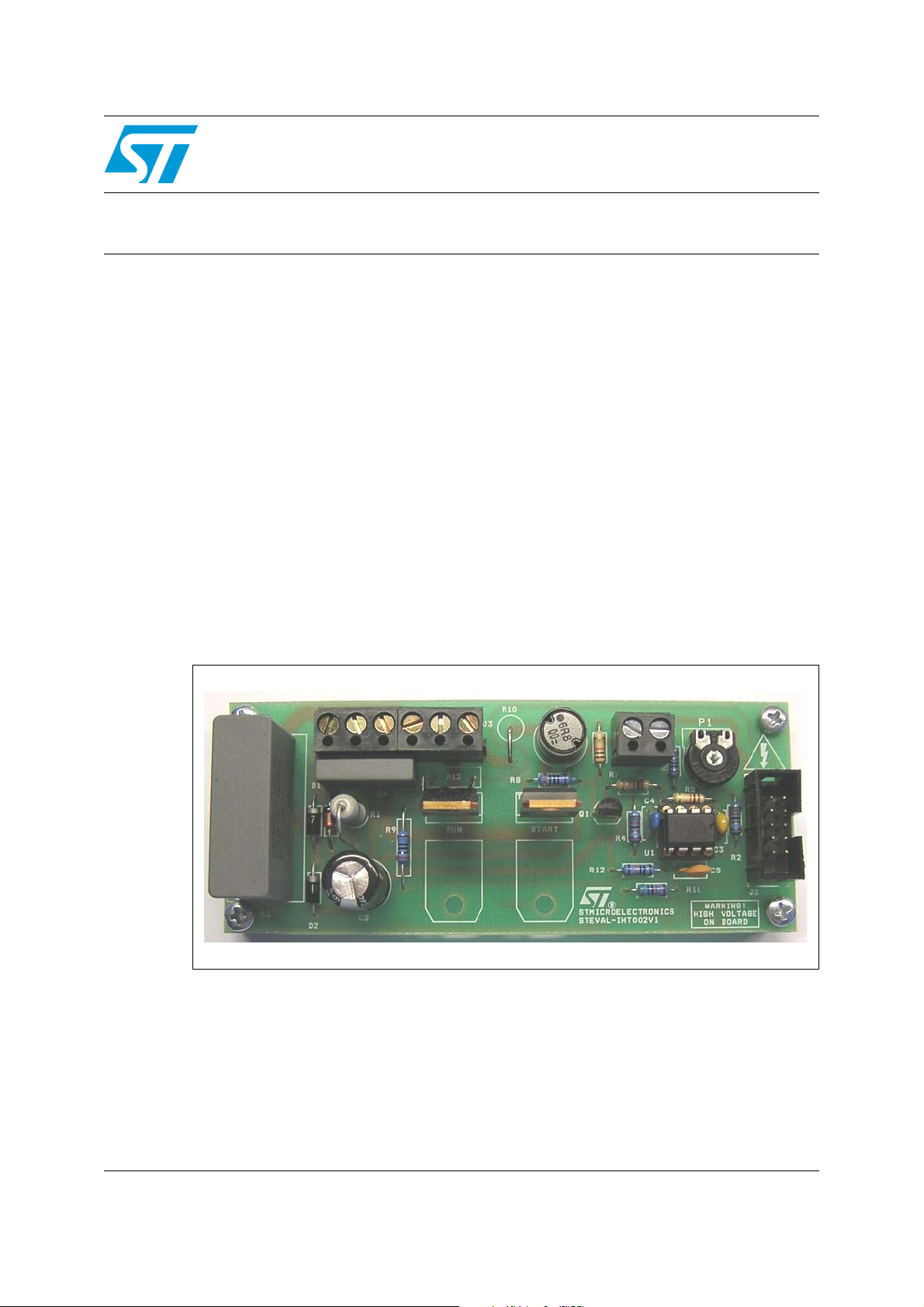
1 STEVAL-IHT002V1 overview
The STEVAL-IHT002V1 evaluation board includes a capacitive power supply on the left side
with the AC switches located in the middle of the board. Both AC switches can work without
a heatsink. The temperature sensor used to detect the stall rotor condition is mounted on
the top of the AC switch driving the RUN winding.
The 8-pin MCU and the ICC programming connector are on the right side of the board.
Figure 1. STEVAL-IHT002V1 evaluation board
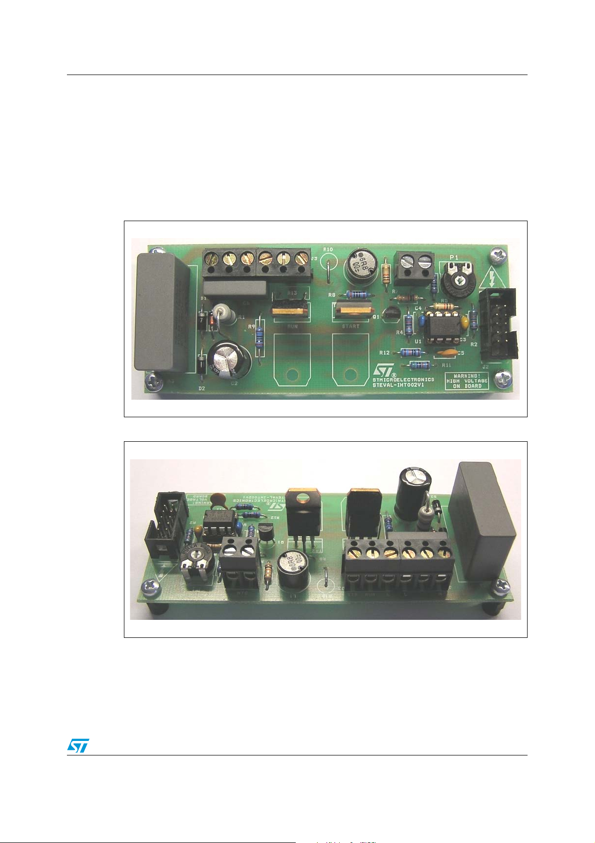
Figure 2. STEVAL-IHT002V1 (reverse angle)
On the left side are the potentiometer to set the cabinet temperature and the connector
where to plug the external NTC sensor. The connector where to plug the compressor and
the voltage mains is on the right side. The AC switch on the left is the one driving the START
winding and the right one drives the RUN winding.
3/13
Page 4
Circuit description AN2446
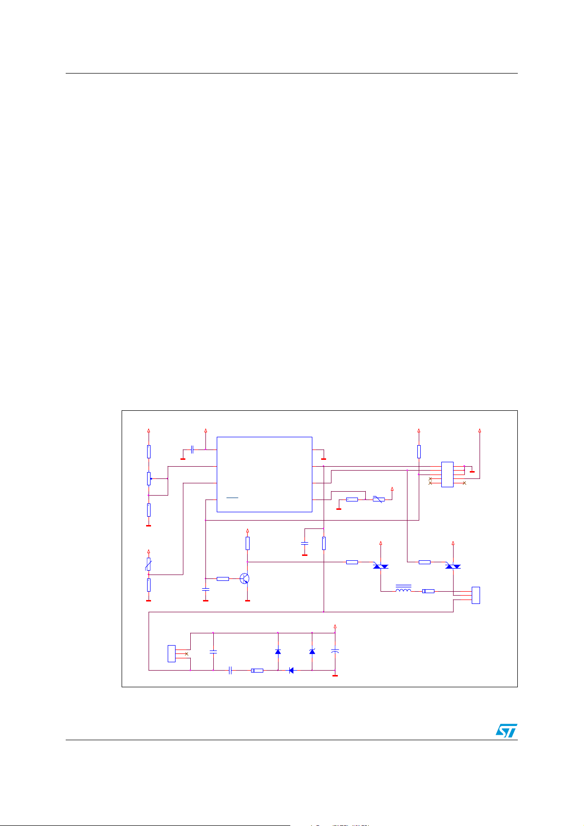
2 Circuit description
The circuit can be divided into a few simple parts.
VDD (5 VDC) is obtained by means of a classic capacitive power supply directly taken from
the mains (220 VAC 50 Hz). Capacitor C1 is sized to provide about 30 mA. VDD supplies
the MCU and all the analog circuitry.
Potentiometer P1 sets the temperature of the cabinet. The signal is sent directly to the MCU
for A/D processing (pin 2). The cabinet temperature is read by means of a negative
temperature coefficient (NTC) thermistor. This signal is also sent directly to the MCU for A/D
processing (pin 3). MCU also generates the gate pulses to drive the AC switches. The gate
current is about 15mA for each AC switch.
Since pin 4 is not able to deliver a current higher than 5mA, a transistor is necessary. Pin 6
indeed has a high current capability up to 20mA; therefore the sole gate resistor is enough
to drive the AC switch.
The gate pulses have to be synchronized with the mains voltage: pin 7 captures the signal
and generates an external interrupt when the mains voltage crosses the zero, on the falling
edge only (one time per period). A resistor divider is applied to pin 5 of the MCU. R13 is
glued on the top of the AC switch driving the RUN winding. R13 is a temperature sensor
used to detect the stall rotor condition by reading the temperature of the AC switch. The
signal is then processed directly by the MCU. The evaluation board is equipped with an ICC
connector to in-circuit program the MCU (care has to be taken while programming the MCU,
please refer to the User's manual for more details).
Figure 3. STEVAL-IHT002V1 schematic
U1
+VDD
+VDD
R14
10K
1%
P1
50K
R2
12K
1%
R3
5K
R4
12K
1%
NEUTRAL
LINE
J1
CON3
MAINS
+VDD
Neutral
C6
47nF
275~ X2
Line
ST7ULTRALITE
1
VDD
2
PA5/AIN4/ CLKIN/ei4
3
PA4/AIN3/MC0/ei3
4
PA3/RESET
R6
10K
C4
10nF
C1
1uF
275~ X2
ei0/ICC DATA/ATPWM/AIN0/PA0
+VDD
R7
10K
Q1
BC337
R1
1W
47
ei1/IC CCLK/AI N1/PA1
ei2/LTIC/ AIN2/PA2
D1
1N4007
D2
1N4007
VSS
C3
100nF
1
2
3
+VDD
+VDD
12
34
56
78
910
TR1
ACST67S
J3
CON3
START
3
RUN
2
LINE
1
+VDD
L1
6.8uH
R5
10K
J2
CON10A
ICC Programmer
R9
COM
300
G
OUT
*
R10
3W
47
8
7
6
5
C5
1nF
DZ1
5V6
1/2W
R11
560K
+VDD
R12
100K 1%
R8
300
C2
+
1000uF
16V
105°C
+VDD
R13
100K
+VDD
COM
G
TR2
ACST67S
OUT
4/13
Page 5

AN2446 How the system works
3 How the system works
The evaluation board can be tested with or without load. In fact, even if no compressor is
connected to the evaluation board, all the signals are clearly visible by means of a scope.
Care has to be taken when using a scope with the evaluation board. For more details,
please refer to the safety instructions described in the User's manual.
Please note that after the evaluation board has been powered on, there is a 3-second delay
before the system starts to operate.
3.1 Cabinet temperature regulation
The potentiometer P1 can be adjusted to set the cabinet temperature in the range of -23 °C
up to +10 °C. Both cabinet temperature and potentiometer settings are read once per
period, meaning 50 times per second (with a mains frequency of 50 Hz).
Once the cabinet temperature rises over the level set by the potentiometer P1, the system
turns the compressor on. The compressor stays on as long as the cabinet temperature
remains below the threshold level set by the potentiometer P1. An offset in the temperature
control is defined in order to avoid oscillations and spurious compressor turn on or off.
3.2 Dead-time
Once the compressor turns off, a delay is set. This delay is called “dead-time”. During this
time, the compressor cannot be turned on again, even if the cabinet temperature exceeds
the threshold level set by the potentiometer P1.
The dead-time is necessary is order to prevent the compressor from turning on immediately
after it was turned off. In fact, the internal high pressure would not let the compressor to spin
again (stall rotor condition).
The dead-time function also helps to avoid spurious compressor turn on and off, therefore
saving in power consumption too.
3.3 Compressor start-up sequence
The evaluation board can drive both the RUN winding and the START winding of a smallsize or mid-size compressor, replacing therefore the positive temperature coefficient (PTC)
thermistor in the START winding.
When the system turns the compressor on, the following steps are performed:
● both RUN winding and START winding are supplied;
● after a certain time, the START winding is no longer supplied;
● RUN winding continues to be supplied as long as the compressor stays on.
The START winding is supplied for 500ms, and then turned off. This time is strictly
dependent on the type of compressor and can be adjusted by modifying the software (see
Section 5.2: START winding duration).
5/13
Page 6

How the system works AN2446
3.4 Stall rotor detection
The system performs the stall rotor detection immediately after the compressor is turned on.
The monitoring lasts 5 seconds. During this time, the system monitors the temperature of
the AC switch driving the RUN winding.
After a normal turning on, meaning when the compressor regularly spins, the current flowing
through the RUN winding is the nominal one. Of course at the very beginning, the in-rush
current is higher than the nominal one, but after a while the current flowing is the nominal
one.
Therefore the increase of the AC switch temperature is smooth.
Attempting to turn on the compressor while the rotor is stalled will result in a higher current
flowing through the RUN winding. Therefore the temperature of the AC switch will increase
faster.
By reading the trend of the temperature, the system is able to determine if the compressor
rotor is stalled or not. In stall rotor condition, the compressor is immediately turned off and
the dead-time is set.
Moreover, the compressor is not turned on when the AC switch temperature goes over 85
°C or goes below 0°C. Dead-time is set as well.
Figure 4. Temperature behavior in normal condition and in stall rotor condition
AC switch temperature
AC switch temperature
Stalled rotor control
Blowing point
By reading the trend of the temperature, the compressor can be turned off faster than any
mechanical device, saving in power consumption. Moreover, the system prevents the AC
switch temperature from reaching the blowing point.
6/13
Page 7

AN2446 Scope waveforms
4 Scope waveforms
The following waveforms have been taken while testing the evaluation board in a real
environment using a common domestic refrigerator.
Figure 5. Compressor while spinning
The mains voltage appears in green, while the brown waveform is the current flowing
through the RUN winding while the compressor is spinning.
The blue waveform is the VDD which supplies the MCU and the analog circuitry.
Finally, the purple waveform represents the pulses applied to the AC switch driving the RUN
winding.
The gate is driven with negative current (or better by sinking the current from the gate pin of
the AC switch). The pulse is applied when the mains voltage crosses the zero, and lasts
about 6.8 ms (corresponding to an angle of 122.4°). The gate pulse is applied twice per
period.
Figure 6. Compressor start-up sequence
7/13
Page 8

Scope waveforms AN2446
When the compressor is turned on, both the RUN winding and the START winding are
supplied. RUN winding is represented in brown, START winding in purple. The current
flowing through the RUN winding at the very beginning is higher than the nominal one, due
to the inrush current. The START winding is supplied for a certain time only (400 ms in the
example), then switched off. The START winding will be supplied again on a new
compressor start only. The blue waveform is the VDD. A voltage drop appears due to the
current needed to drive the AC switches. In any case, the voltage drop is not big enough to
affect the correct operation of the evaluation board.
Figure 7. Stall rotor detection
The compressor is turned on while the rotor is stalled. The green waveform is the START
winding, the brown waveform the RUN winding and the blue one the gate pulses applied to
the AC switches. After a certain time, the pulses are not applied anymore; the compressor is
turned off and no voltage is present on the compressor windings. The stall rotor condition is
detected by reading the temperature of the AC switch driving the Run winding. In the
example the stall rotor has been detected after 4 seconds. Parameters how to detect the
stall rotor condition can be modified by the user are described in Section 5.3: Stall rotor
control duration.
8/13
Page 9

AN2446 Customization: software and hardware modifications
5 Customization: software and hardware modifications
The STEVAL-IHT002V1 evaluation board can be fully adapted to the compressor the user
intends to test. Different parameters such as the temperature offset or the dead-time period
can be changed. Only a few easy software or hardware modifications are necessary.
5.1 Cabinet temperature offset
There is only one variable for the cabinet temperature offset. Therefore the positive offset is
equal to the negative one.
The constant to be modified is named Offset, defined in the main() routine, where the
defines are declared. The value is expressed in bits.
The range between 0°C and 5°C corresponds to 50 bits. So 1 °C is approximately 10 bits.
Default value: 15 (possible range: 0 to 255)
5.2 START winding duration
When the compressor is turned on, both the RUN winding and the START winding are
supplied. After a while, the START winding is no longer supplied.
The time the START winding is supplied can be changed. The constant to be modified is
named START_Period, defined in the main() routine, where the defines are declared.
The value is expressed in periods.
A value of 10 means therefore 10 periods, equal to 200 milliseconds (mains frequency
50 Hz).
Default value: 25 (possible range: 0 to 255).
5.3 Stall rotor control duration
The stall rotor control starts as soon as the compressor is turned on and lasts a certain time.
This time can be changed. The constant to be modified is named Window_Period, defined
in the main() routine, where the defines are declared. The value is expressed in tens of
milliseconds.
A value of 1000 means 10000 milliseconds, or 10 seconds. It is suggested not to exceed a
value of 10000.
Default value: 500 (possible range: 0 to 65535, in any case, do not exceed 10000).
5.4 Dead-time duration
The dead-time is set once the compressor is turned off or when a stall rotor condition has
been detected. During this time, the compressor cannot be turned on, even if the cabinet
temperature rises up over the threshold set by the user.
There is one constant only. Therefore the dead-time set after the compressor turn off and
the dead-time set after a stall rotor detection are the same.
9/13
Page 10

Customization: software and hardware modifications AN2446
The constant to be modified is named Dead_Time_Period, defined in the main() routine,
where the defines are declared. The value is expressed in tens of milliseconds.
A value of 10000 means 100000 milliseconds, or 100 seconds, or 1 minute and 40 seconds.
Default value: 12000 (possible range: 0 to 65535).
5.5 Gate pulse duration
The gate pulses are applied to the AC switches, which in turn drive the RUN winding and the
START winding of the compressor. The gate pulse applied to the RUN winding has the
same duration of the one applied to the START winding.
The gate pulses are applied when the mains voltage crosses the zero. Therefore, twice per
period.
The constant to be modified is named DURATION, defined in the ports() routine, where
the defines are declared. One point is equal to 400 µs.
A value of 10 means 4000 µs, or 4 ms, or an angle of 72°. Since half of a period is 10 ms
(mains frequency 50 Hz), care has to be taken while changing this constant.
Default value: 17 (possible range: 0 to 255, in any case do not exceed 25).
5.6 Disabling the stall rotor detection
Basically, the stall rotor detection reduces the power consumption when attempting to turn
on a stalled compressor, also keeping the AC switch from getting damaged.
In any case, when testing a small compressor (meaning 1 A nominal current and 5A when in
stall condition), the stall rotor detection can be disabled without damaging the AC switch.
No software modification is required. Simply unsolder the R13 temperature sensor and
replace it with a 100 KΩ 5% ¼ W resistor.
5.7 Different START winding management
The evaluation board drives directly the START winding avoiding the use of the PTC.
If the PTC cannot be removed from the original circuitry, the AC switch will simply switch the
PTC off after the compressor is spinning.
The PTC can drive the START winding without using the AC switch too. In this case, the
evaluation board will drive the RUN winding only. No hardware or software modifications are
required.
10/13
Page 11

AN2446 Bill of materials
Appendix A Bill of materials
Table 1. Bill of materials
Item Quantity Reference Part Supplier
1 1 C1 1µF 275VAC X2
2 1 C2 1000 µF 16 V
3 1 C3 100 nF ceramic
4 1 C4 10 nF ceramic
51C51 nF ceramic
6 1 C6 47 nF 275VAC X2
7 1 DZ1 5.1 V Zener 1.3 W
8 2 D1, D2 1N4007
92J1, J3CON3
10 1 J2 CON10A
11 1 L1 6.8 µH 20% 2.8 A
12 1 P1 50 KΩ potentiometer
13 1 Q1 BC337
14 2 R1, R10
(1)
47 Ω 2 W flame proof
15 2 R2, R4 12 KΩ 1% ½ W metal oxide
16 1 R3 M2020/5K/A206 NTC EPCOS
17 3 R5, R6, R7 10 KΩ 5% ¼ W carbon
18 1 R14 10 KΩ 1% ½ W metal oxide
19 2 R8, R9 300 Ω 1% ½ W metal oxide
20 1 R11 560 KΩ 5% ¼ W carbon
21 1 R12 100 KΩ 1% ½ W metal oxide
22 1 R13 100 KΩ NTC 2381 633 5.104 VISHAY
23 2 TR1, TR2 ACST67S TO-220 ST
24 1 U1 ST7FLITEU5Y0B6 ST
1. Used during internal test only (short circuited during normal operation)
11/13
Page 12

Revision history AN2446
6 Revision history
Table 2. Revision history
Date Revision Changes
14-Feb-2007 1 Initial release.
12/13
Page 13

AN2446
Please Read Carefully:
Information in this document is provided solely in connection with ST products. STMicroelectronics NV and its subsidiaries (“ST”) reserve the
right to make changes, corrections, modifications or improvements, to this document, and the products and services described herein at any
time, without notice.
All ST products are sold pursuant to ST’s terms and conditions of sale.
Purchasers are solely responsible for the choice, selection and use of the ST products and services described herein, and ST assumes no
liability whatsoever relating to the choice, selection or use of the ST products and services described herein.
No license, express or implied, by estoppel or otherwise, to any intellectual property rights is granted under this document. If any part of this
document refers to any third party products or services it shall not be deemed a license grant by ST for the use of such third party products
or services, or any intellectual property contained therein or considered as a warranty covering the use in any manner whatsoever of such
third party products or services or any intellectual property contained therein.
UNLESS OTHERWISE SET FORTH IN ST’S TERMS AND CONDITIONS OF SALE ST DISCLAIMS ANY EXPRESS OR IMPLIED
WARRANTY WITH RESPECT TO THE USE AND/OR SALE OF ST PRODUCTS INCLUDING WITHOUT LIMITATION IMPLIED
WARRANTIES OF MERCHANTABILITY, FITNESS FOR A PARTICULAR PURPOSE (AND THEIR EQUIVALENTS UNDER THE LAWS
OF ANY JURISDICTION), OR INFRINGEMENT OF ANY PATENT, COPYRIGHT OR OTHER INTELLECTUAL PROPERTY RIGHT.
UNLESS EXPRESSLY APPROVED IN WRITING BY AN AUTHORIZED ST REPRESENTATIVE, ST PRODUCTS ARE NOT
RECOMMENDED, AUTHORIZED OR WARRANTED FOR USE IN MILITARY, AIR CRAFT, SPACE, LIFE SAVING, OR LIFE SUSTAINING
APPLICATIONS, NOR IN PRODUCTS OR SYSTEMS WHERE FAILURE OR MALFUNCTION MAY RESULT IN PERSONAL INJURY,
DEATH, OR SEVERE PROPERTY OR ENVIRONMENTAL DAMAGE. ST PRODUCTS WHICH ARE NOT SPECIFIED AS "AUTOMOTIVE
GRADE" MAY ONLY BE USED IN AUTOMOTIVE APPLICATIONS AT USER’S OWN RISK.
Resale of ST products with provisions different from the statements and/or technical features set forth in this document shall immediately void
any warranty granted by ST for the ST product or service described herein and shall not create or extend in any manner whatsoever, any
liability of ST.
ST and the ST logo are trademarks or registered trademarks of ST in various countries.
Information in this document supersedes and replaces all information previously supplied.
The ST logo is a registered trademark of STMicroelectronics. All other names are the property of their respective owners.
© 2007 STMicroelectronics - All rights reserved
STMicroelectronics group of companies
Australia - Belgium - Brazil - Canada - China - Czech Republic - Finland - France - Germany - Hong Kong - India - Israel - Italy - Japan -
Malaysia - Malta - Morocco - Singapore - Spain - Sweden - Switzerland - United Kingdom - United States of America
www.st.com
13/13
 Loading...